C800 - Electric lock Dormakaba - Free user manual and instructions
Find the device manual for free C800 Dormakaba in PDF.


| Brand | Dormakaba |
| Model | C800 |
| Product Type | Electrified Cylindrical Lock |
| Functions | EU (Fail Secure), EL (Fail Safe), RX (Request to Exit) |
| Power Supply | 24V AC/DC ±10%, 0.145A operating current |
| Solenoid Type | Continuous duty |
| RX Switch Rating | 250VAC, 1A, 22AWG leads |
| Backset Options | 2 3/4" (70mm) or 2 3/8" (60mm) |
| Cylinder Pocket Diameter | 2 1/8" (54mm) |
| Raceway for Electrified Functions | 3/8" (9.5mm) diameter |
| Raceway for RX Functions | 3/4" (19mm) diameter |
| Wire Transfer Hinge | Required, not furnished |
| Wire Gauge | 22 AWG for field connections |
| Installation | Must comply with local electrical codes |
| Warranty | Void if rectifier module is removed |
Frequently Asked Questions - C800 Dormakaba
User questions about C800 Dormakaba
0 question about this device. Answer the ones you know or ask your own.
Ask a new question about this device
Download the instructions for your Electric lock in PDF format for free! Find your manual C800 - Dormakaba and take your electronic device back in hand. On this page are published all the documents necessary for the use of your device. C800 by Dormakaba.
USER MANUAL C800 Dormakaba
C800 ELECTRIFIED CYLINDRICAL LOCK INSTALLATION INSTRUCTIONS

1. Function Description:
EU - Electrically Unlocked (Fail Secure):
When power is applied the outside trim will unlock. With power removed the outside trim is locked.
EL - Electrically Locked (Fail Safe):
When power is applied the outside trim will lock. With power removed the outside trim is unlocked.
RX - Request to Exit:
A microswitch attached to the chassis is activated when the inside lever is rotated. The switch signals the use of the lever to security systems allowing a non-disruptive means of immediate egress.
2. Electrical Specifications:
| Electrified Functions | RX Functions | |
| EU and EL | RX | EU-RX and EL-RX |
| - 24 Volts AC/DC +/-10 %operating current .145AMP* All solenoids are continuous duty type. | - Voltage 250VAC- Current rating: 1AMP- Wire leads: 22AWGThe 3-wire utilizes a UL recognized SPDT switch providing a choice of:* Normally closed operation use the white (COM.) & gray wires* Normally open operation use the white(COM.) & purple wires | |
 NOTE: Warranty is void if rectifier module is removed. NOTE: Warranty is void if rectifier module is removed. |  |  |
3. Wiring Diagram for Electrified Locks:

flowchart
graph LR
    A["Rectifier Module"] --> B["To Lock"]
    B --> C["Wire Transfer Hinge"]
    C --> D["Switch (Not Furnished)"]
    D --> E["24VAC/DC"]
    E --> F["Power Supply (Not Furnished)"]
NOTE: All installations should be in accordance with local electrical codes.
4. Installation Instructions:
A. Door Preparation
a. The door must be machined with a 3/8" wire raceway, Cyl. lock pocket & prepped for a wire transfer hinge. Make sure the pocket is free of debris.
b. Provide a 5/8" dia. hole extending 6" to 8" in depth from back edge of Cyl. lock pocket. This provide room for insertion of rectifier module and wires.
c. Provide a 3/8" dia. through hole for electrified functions or provide a 3/4" dia. for RX functions.

B. Install Wire Route
a. Run the wires from the wire transfer hinge through the 3/8" raceway starting at the wire transfer hinge & exiting into the Cyl. lock pocket.
b. Screw the wire transfer hinge to the door (at this time DO NOT connect the hinge wires on the jamb side to the wires coming from the power supply).

C. Install Outside Trim
a. Electrified Functions:
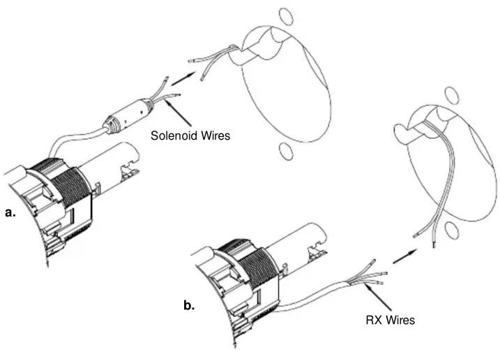
Terminate the two blue wires from lock to the wire transfer hinge device using 22AWG wire. Use proper crimp splices or wire nuts for terminating connections. (No Polarity of wire is required)
b. RX Functions:
Terminate the three wires from lock to the wire transfer hinge device using 22AWG wire. Use proper crimp splices or wire nuts for terminating connections.
c. Carefully slip the connected Cyl. lock chassis into the pocket paying close attention not to pinch any wires.
D. Follow UP
a. Mount the Cyl. lock per manufacturer's instructions.
b. Connect the wires from the power supply at the wire transfer hinge on the jamb side. Connect the wire transfer hinge to the jamb.

Brand : Dormakaba
Model : C800
Category : Electric lock