
IAN 273687 - Outdoor wall light Livarno Lux - Free user manual and instructions
Find the device manual for free IAN 273687 Livarno Lux in PDF.


| Product Type | LED Outdoor Wall Light |
| Model Numbers | 14109002L (with motion sensor), 14109302L (without motion sensor) |
| Operating Voltage | 230-240 V ~ 50 Hz |
| Bulb Type | GU10, 5 W LED |
| Total Power (Max) | 5 W (model 14109002L), 10 W (model 14109302L, 2 x 5 W) |
| Protection Class | I |
| Protection Type | IP44 (splash-proof) |
| Detection Angle (Motion Sensor) | Approx. 80°–100° (model 14109002L only) |
| Detection Range (Motion Sensor) | Approx. 6–8 m (model 14109002L only) |
| Light Duration (Adjustable) | 10 s – 4 min (model 14109002L only) |
| Twilight Sensor | Yes, adjustable light sensitivity (model 14109002L only) |
| Intended Use | Indoor and outdoor use, mountable on normally inflammable surfaces |
| Scope of Delivery | LED wall light, fixing screws, wall plugs, LED bulbs, protective tubes, assembly and user instructions |
| Cleaning | Disconnect power, allow to cool, use dry lint-free cloth only |
| Warranty | 36 months from date of purchase |
| Safety Certifications | CE, RoHS, complies with EU directives |
Frequently Asked Questions - IAN 273687 Livarno Lux
User questions about IAN 273687 Livarno Lux
0 question about this device. Answer the ones you know or ask your own.
Ask a new question about this device
Download the instructions for your Outdoor wall light in PDF format for free! Find your manual IAN 273687 - Livarno Lux and take your electronic device back in hand. On this page are published all the documents necessary for the use of your device. IAN 273687 by Livarno Lux.
USER MANUAL IAN 273687 Livarno Lux
natural_image
Metal cylindrical object with a circular recess, shown against a plain white background (no text or symbols)
natural_image
Modern glass and metallic wall-mounted device with a pointed glass top (no text or symbols visible)
APLIQUE LED PARA EXTERIORES
ES
APLIQUE LED PARA EXTERIORES
Assembly and safety advice
PT
CANDEEIRO LED PARA PAREDE EXTERIOR
Before reading, unfold both pages containing illustrations and familiarise yourself with all functions of the device.
DE AT CH
GB Assembly and safety advice Page 21
natural_image
Technical line drawing of a cylindrical device with a grid base and circular component, no text or symbols present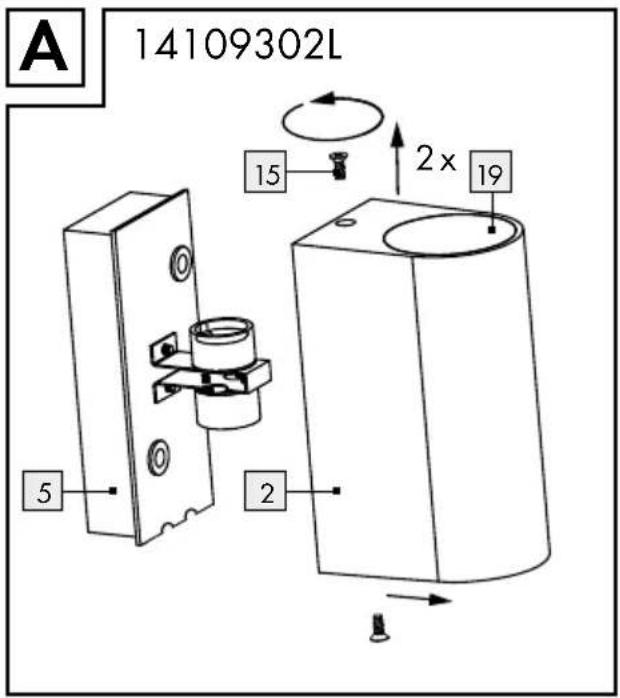



natural_image
Simple line drawing of a door frame with a letter 'E' on the left corner (no text or symbols on the door itself)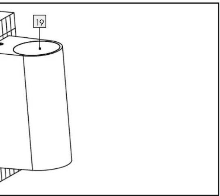
Introducción
80^-100^
dependiendo
altura del montaje
Intended use......Page 22
Parts description Page 22
Scope of delivery....Page 22
Technical Data Page 22
Safety information
For your safety......Page 23
Preparation
Required tools and material Page 23
Prior to installation......Page 24
Installation......Page 24
Set up
Setting the lighting duration....Page 25
Setting the light sensitivity....Page 25
Setting the sensitivity....Page 25
Replacing a bulb Page 25
Cleaning Page 26
Disposal Page 26
Warranty and Service
Warranty Page 26
Service Address......Page 26
Declaration of conformity....Page 26
Manufacturer......Page 27
LED outdoor wall light
- Introduction

Congratulations on the purchase of your new product. You have selected a high quality product. These instructions are part of the product and contain important information on setup and handling. Always follow all safety instructions. Before using this product for the first time, verify that the voltage is correct and that all parts are properly installed. Should you have any questions or you are unsure about operating the product, please contact the dealer or service centre. Please keep these instructions in a safe place and pass them on to third parties as applicable.
Intendeduse
This light is suitable for indoor and outdoor use. The light can be fastened to any normally inflammable surface.
- Parts description
1 Lamp glass
2 Light body
3 Nut
4 Wall plate
5 Connection housing
6 Bulb
7 Retaining screw
8 Mains connection lead
9 Lustre terminal
10 Membrane
11 Plastic washer
[12] Rotary control SENS (detection distance) (model 14109002L only)
13 Rotary control LUX (light sensitivity) (model 14109002L only)
14 Rotary control TIME (switched on duration) (model 14109002L only)
15 Screw (model 14109302L only)
16 Protectivetube
17 Connector plug (model 14109302L only)
18 Sealing ring (model 14109002L only)
19 Protective glass (model 14109302L only)
20 Screws for cover cap (model 14109302L only)
21 Cover cap (model 14109302L only)
- Scope of delivery
1 LED outdoor wall light, models 14109002L and 14109302L
2 Fixing screws
2 Wall plugs
2 LED lamps, GU10, 5 W (14109302L)
1 LED lamp, GU10, 5 W (14109002L)
2 Protective tubes
1 Set of assembly instructions and instructions for use
●TechnicalData
Article no.: 14109002L and 14109302L
Operating voltage: 230-240V\~50Hz
Bulb: 220-240V\~50Hz, GU10, 5W
Rated power max.: 14109302L:
$$ 2 \times 5 W $$
$$ 1 4 1 0 9 0 0 2 \mathrm{L}: $$
$$ 1 \times 5 W $$
Protectionclass: 1/ ⊥
Protectiontype: IP44
Model 14109002L only:
Detection angle
(Motion sensor):

approx.
80^ - 100^
depending on
mounted height
Detection range
Motion detector:

approx. 6–8 m
Light duration:
10 s-4 min with twilight sensor

Safety information

RISK OF LOSS OF LIFE AND ACCIDENT TO INFANTS AND
CHILDREN! Never leave children unattended with the packaging material. The packaging material represents a danger of suffocation. Children frequently underestimate the dangers. Please keep children away from the product at all times.

Danger to life from electric shock!
■ Ensure that a qualified electrician, or a person trained to carry out electrical installations, performs the electrical installation.
We assume no liability for material damage or personal injury due to improper handling or failure to comply with the safety instructions!
■ Never use the light if any defects have been identified.
Prior to installation, remove the fuse or switch off the circuit breaker (O setting) in the fuse box. Set the light switch to the „Off" position.
Prior to installation, verify that the mains voltage on site corresponds with the operating voltage required for the light (230-240 V \~).
- Ensure that no cables are damaged when installing.

Risk of burns and injury!
Do not install the light, if it has a defective lamp glass. In this case contact the service centre for a replacement.
The light may be installed on all normal inflammable surfaces.
To prevent burns, ensure that the light is switched off and has cooled down before touching it. Light bulbs develop a great deal of heat.
- Allow the light to cool down completely before replacing a defective bulb.
- Do not attach the light to a damp or conductive substrate.
- Replace defective bulbs with new ones immediately. Use only those bulbs as stated in the chapter on "Technical Data". Before changing bulbs, always first remove the fuse or switch off the circuit breaker.
The type of bulb included is not
suitable for dimmer or electronic switches.
■ Only use the individual parts supplied, otherwise all warranty claims will become invalid.

Model 14109002L only:
Do not operate the lights with defective lamp glass. Replace defective lamp glass.
Model 14109302L only:
If the lights have defective protective glass, they must be disposed of, as otherwise protection class IP44 will no longer apply
For your safety
☐ Only use 220-240 V \~ bulbs with a GU10 socket and a maximum output of 5 watt.
☐ The outdoor light is splash-proof.
□ Always be attentive when working! Always pay attention to what you are doing and act with common sense. Never install the light if you are having difficulty concentrating or do not feel well.
☐ Do not look directly into the light source (light bulb, LED etc.).
☐ Do not look at the light source (light bulb, LED etc.) with an optical instrument (e.g. magnifier).
● Preparation
- Required tools and material
The tools and materials specified are not included. This information and these values are non-binding and they are only for guidance. The nature of the material is determined by the individual local conditions.
- Pencil /marking tool
- Voltage tester
- Cross-tip screwdriver
- Electric drill
- Edge cutter
- Allen hexagon key 8 mm
Prior to installation
Important: Ensure that a qualified electrician, or a person trained to carry out electrical installations, performs the electrical installation.
- Familiarise yourself with all the instructions and diagrams in this manual, as well as with the light itself, before you install it.
Before installation ensure that the circuit, to which the light will be connected, is not energised. To do this, remove the fuse or switch off the circuit breaker in the fuse box (0 setting). - Use the voltage tester to verify the de-energised status.
- Installation
Model 14109002L:
□ Unscrew the lamp glass from the light body 2.
☐ Remove the nuts 3 visible at the front of the wall plate 4 and the plastic washers 11, and open the connection housing 5 (see Fig. A).
☐ Use the holes in the connection housing 5, which are intended for the screws, to mark the drill holes. Open these holes (if they are not open) with a pointed object (e.g. screwdriver). Ensure that you fasten the connection housing with the arrow facing upwards (inside the connection housing).
☐ Now drill the fixing holes (ø approx. 6 mm, depth approx. 40 mm). Ensure that you do not damage the electrical supply line.
☐ Now introduce the wall plugs into the drill holes.
☐ Slide the mains connection lead 8 through the cable entry with the membrane 10.
☐ Pull the protective tube over the mains connection lead 8.
☐ Fasten the connection housing with the fixing screws included 7, (see fig. B).
☐ Connect the connection cable of the light to the mains connection lead 8 by means of the lustre terminal 9, see fig. C.
Also ensure that the colour connection of the wires is correct when connecting (L or 2 = black or brown, N or 1 = blue or white).
☐ Now connect the earth wire (3 = green-yellow) to the marked earth terminal ⊥ (see fig. C).
Now carefully attach the wall plate 4 over the connection housing 5, attach the plastic washers 11 and secure with the two nuts 3.
□ Check for correct fitting.
☐ Insert the bulb into the socket carefully and tighten it with a 14 turn clockwise.
Place the lamp glass over the light fixture 2 and screw it tightly. Be sure the sealing ring 18 makes contact with the lamp glass 1 (see Fig. D).
☐ Reinsert the fuse or switch the circuit breaker back on.
☐ Your light is now ready for use (see fig. E).
Model 14109302L:
☐ Unscrew the light body 2 from the connection housing 5 by loosening the screws 15 anticlockwise (Fig. A).
☐ Use the holes in the connection housing 5, which are intended for the screws, to mark the drill holes. Ensure that that you fasten the connection housing 5 with the arrow facing upwards (on the rear of the connection housing).
☐ Now drill the fixing holes (∅ approx. 6 mm, depth approx. 40 mm). Be sure not to damage the supply line.
☐ Now introduce the wall plugs into the drill holes.
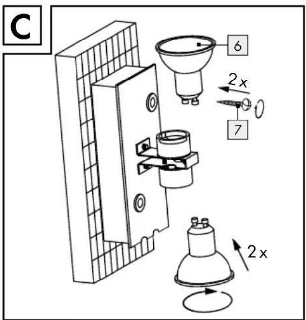
Open the connection socket 17 on the rear of the connection housing 5 by unscrewing the 4 screws 20 anti-clockwise.
□ Remove the cover cap 21.
☐ Pull the protective tube 16 over the mains connection lead 8.
- Connect the connection cable of the light to the power cord 8 using the terminal block 9 (Fig. B).
☐ Also ensure that the colour connection of the wires is correct when connecting (L or 2 = black or brown, N or 1 = blue).
☐ Connect the earth wire (3 = green-yellow) to the marked earth terminal ⊥ (Fig. B).
☐ Close the connection socket 17 on the rear of the connection housing 5. Place the cover cap 21 on the connector socket 17 and turn the 4 screws 20 clockwise.
☐ Fasten the connection housing 5 with the screws which are included 7 (Fig. C).
☐ Use a clean, lint-free cloth to insert the lamp.
☐ Insert the bulb 6 GU10, 5 W, into the socket carefully and tighten it with a 14 turn clockwise.
☐ Screw the light body 2 into the connection housing 5 again by tightening the screws 15 clockwise (Fig. D).
☐ Check for correct fitting.
☐ Your light is now ready for use (Fig. E).
☐ Reinsert the fuse or switch the circuit breaker back on.
- Set up (14109002L)
- Setting the lighting duration
☐ Set the light duration using the TIME rotary control 14.
☐ Turn clockwise to increase the on time. Turn anti-clockwise to decrease the on time.
- Setting the light sensitivity
☐ Set the desired light sensitivity using the LUX rotary control 13.
☐ Turn clockwise to increase the light sensitivity. The light is more sensitive to changes in light intensity and switches to automatic mode sooner.
☐ Turn anti-clockwise to decrease the light sensitivity. The light is less sensitive to changes in light intensity and takes longer to switch to automatic mode.
Note: With the LUX control dial 13 at the highest position, the motion detector will work day and night. With the LUX control dial 13 in the lowest position, the motion detector will only work at night.
- Setting the sensitivity
☐ Set the motion sensor to the desired sensitivity (sensitiveness to movement) using the SENS rotary control 12.
☐ Turn clockwise to increase the sensitivity (max. 8 m). Turn anti-clockwise to decrease the sensitivity (min. 2 m).
● Replacing a bulb
CAUTION! RISK OF ELECTRIC SHOCK!
To replace the bulb, first of all disconnect the light from the mains circuit. To do this, remove the fuse or switch off the circuit breaker in the fuse box (0 setting).
- Allow the light to cool completely.
☐ Use a dry, lint-free cloth to replace a bulb.
Model 14109002L:
□ Unscrew the lamp glass from the light body 2 (see Fig. A).
Model 14109302L:
☐ Unscrew the light body from the connection housing 5 by loosening the screws 15 anti-clockwise (Fig. A).
Model 14109002L + 14109302L:
☐ Turn the defective bulb out of the socket with a 14 turn anticlockwise.
☐ Insert a new bulb in the socket and tighten it with a 14 turn clockwise.
Model 14109002L:
Place the lamp glass over the light fixture 2 and screw it tightly.
Ensure that the sealing ring on the lamp glass 1 is present and in contact (see Fig. D).
Model 14109302L:
Screw the light body into the connection housing 1 again by tightening the screws 15 clockwise (Fig. D).
Model 14109002L + 14109302L:
□ Check for correct fitting.
☐ Reinsert the fuse or switch the circuit breaker back on.
- Cleaning
CAUTION! RISK OF ELECTRIC SHOCK!
Disconnect the light from the mains circuit before cleaning. To do this, remove the fuse or switch off the circuit breaker in the fuse box (0 setting).
- Allow the light to cool completely.
■ Only use a dry, lint-free cloth for cleaning. Do not use solvents, spirit or similar substances. They could damage the light.
☐ Reinsert the fuse or switch the circuit breaker back on.
- Disposal

The package and packaging materials consist entirely of environmentally friendly materials. They can be disposed of at your local recycling facility.

The symbol of the wheelie bin with the line through it means that, in the European Union, the product has to be disposed
of in a separate refuse collection. This applies to the product and to all components bearing this symbol. Do not dispose of products bearing this symbol in your normal household waste, but instead they must be taken for recycling to a collection site for electrical and electronic appliances. Recycling helps to reduce the consumption of raw materials and protects the environment.
- Warranty and Service
Warranty
You receive a 36 month warranty on this product, valid from the date of purchase.
The appliance has been carefully produced under strict quality control.
We will rectify without charge all material and manufacturing defects within the warranty period. In the event of a defect arising during the warranty period, please send the appliance to the listed Service Centre address, making reference to the following article number: 14109002L / 14109302L. Wearing parts (such as light bulbs) and damage caused by improper handling, non-observance of the operating instructions or unauthorised interference with the appliance are excluded from the warranty.
The performance of services under the warranty does not extend or renew the warranty period.
Service Address
For all inquiries about your product, please have your receipt and the article number (e.g.
IAN 12345) ready as your proof of purchase.
Declaration of conformity
This product fulfils the requirements of the applicable European and national directives (Electromagnetic Compatibility 2004/108/EC, Low Voltage Directive 2006/95/EC, Ecodesign Directive 2009/125/EC, RoHS Directive 2011/65/EU).
Conformity has been demonstrated. The relevant declarations and documents are held by the manufacturer.
Manufacturer
59929 Brilon (Germany)


- APLIQUE LED PARA EXTERIORES
- CANDEEIRO LED PARA PAREDE EXTERIOR
- Introducción
- Safety information
- Preparation
- Set up
- Warranty and Service
- LED outdoor wall light
- - Introduction
- Intendeduse
- - Parts description
- - Scope of delivery
- ●TechnicalData
- Model 14109002L only:
- RISK OF LOSS OF LIFE AND ACCIDENT TO INFANTS AND
- Danger to life from electric shock!
- Risk of burns and injury!
- Model 14109302L only:
- For your safety
- ● Preparation
- - Required tools and material
- Prior to installation
- - Installation
- Model 14109002L:
- Model 14109302L:
- - Set up (14109002L)
- - Setting the lighting duration
- - Setting the light sensitivity
- - Setting the sensitivity
- ● Replacing a bulb
- CAUTION! RISK OF ELECTRIC SHOCK!
- Model 14109002L + 14109302L:
- - Cleaning
- - Disposal
- - Warranty and Service
- Warranty
- Service Address
- Declaration of conformity
- Manufacturer
Brand : Livarno Lux
Model : IAN 273687
Category : Outdoor wall light