
TECHNIPRO RV 700-8E - Uncategorized TECHNISAT - Free user manual and instructions
Find the device manual for free TECHNIPRO RV 700-8E TECHNISAT in PDF.


| Product Type | Programmable Single-Cable Outlet (End Outlet, Terminated) |
| Brand | TechniSat |
| Model | TECHNIPRO RV 700-8E |
| Item Number | 0000/3192 |
| Connections | TV: IEC male (IEC 61169-2); Radio: IEC female (IEC 61169-2); SAT: F-socket (IEC 61169-24) |
| Standards Compliance | EN 60728-11, EN 50083-2; Single-cable systems EN 50494 and EN 50607 |
| Screening Factor | 5-300 MHz ≥85 dB; 300-470 MHz ≥80 dB; 470-950 MHz ≥75 dB; 950-2150 MHz ≥55 dB |
| Through Loss (5-10 MHz) | 1.5 dB |
| Through Loss (10-862 MHz) | 1.1 dB |
| Through Loss (862-2150 MHz) | 1.9 dB |
| Insertion Loss (TV 5-68/118-862 MHz) | 8 dB |
| Insertion Loss (SAT 950-2150 MHz) | 8 dB |
| Insertion Loss (Radio 87.5-108 MHz) | 9 dB |
| Decoupling (between subscribers) | 5-862 MHz ≥42 dB; 950-2150 MHz ≥32 dB |
| Power Supply | DC feed-through via SAT connection, max 24 V/400 mA; 22 kHz and DiSEqC signal compatible |
| Functionality | Monitors DiSEqC signaling; overload protection (electronic fuse + decoupling diodes); automatic switch-off if no single-cable DiSEqC command |
| Configuration | Via Programming Unit RVP 700 (item 0000/3189) and TechniSat RV-control app; enables up to 32 user bands (UB1-UB32) |
| LED Indicators | Red: 18V/22kHz signal >400ms, overload >500mA, or DiSEqC with disabled user band; Green: programming mode; Green flashing: DiSEqC with enabled user band |
| Installation | For flush-mounted boxes ∅ 55-65 mm; screw and claw fastening; strip cable per diagram; connect inner conductor; use knife/stripping aid and Phillips/flat screwdriver |
| Safety | Install by qualified personnel; use indoors in dry areas; avoid damaging outer conductor; do not touch claw tips; dispose per local regulations (WEEE) |
| Disposal | Return to public collection points; comply with EU directives; CE-marked |
Frequently Asked Questions - TECHNIPRO RV 700-8E TECHNISAT
User questions about TECHNIPRO RV 700-8E TECHNISAT
0 question about this device. Answer the ones you know or ask your own.
Ask a new question about this device
Download the instructions for your Uncategorized in PDF format for free! Find your manual TECHNIPRO RV 700-8E - TECHNISAT and take your electronic device back in hand. On this page are published all the documents necessary for the use of your device. TECHNIPRO RV 700-8E by TECHNISAT.
USER MANUAL TECHNIPRO RV 700-8E TECHNISAT
Programmable single-cable outlets
TechniSat

Inhaltsverzeichnis
1 Characteristics....6
2 Functional Specification....6
3 Notes for the Installer....7
4 Installation....7
4.1 Tools 7
4.2 Installation and Safety Instructions....7
4.3 Installing the Outlet 8
4.4 Service LED 8
5 Technical Data....8
1 Merkmale
natural_image
Close-up of a TechniSat device connected to an electrical terminal block (no visible text or symbols on the main body)Abb. 2: PROGRAMMIERADAPTER RVP 700 an RV 700-14E angeschlossen.
DE
4 Montage
4.1 Werkzeug
natural_image
Pure electrical circuit lines without any symbols- For single-cable systems according to EN 50494 and EN 50607
- With DC voltage feed-through via satellite connection to the trunk line (max. 24 V/400 mA, 22 kHz- and DiSEqC™ signal)
• Monitoring of DiSEqC ^TM signalling by microcontroller
• Overload protection by means of an electronic fuse and decoupling diodes - Return-path compatible for systems with cable connection (CATV modem)
- Configurable functions with the PROGRAMMING UNIT RVP 700:
– disabling individual user bands
- operation in Legacy mode (no switch-off at 18 V constant signal for standard multi-switch system)
— operation in disconnect mode (no DC feed-through to the trunk)
— LED display for status and fault indication (can be switched off)
— Functions can be expanded.
- Basic functions at delivery:
- The connected receiver is switched off if it does not use the single-cable DiSEqC™ command set in accordance with EN 50494 or EN 50607 (switching off the power from the satellite connection to the input at +18 VDC after approx. 400 ms).
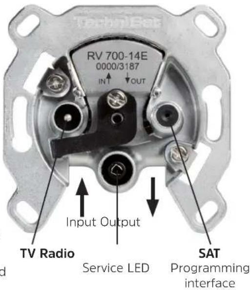
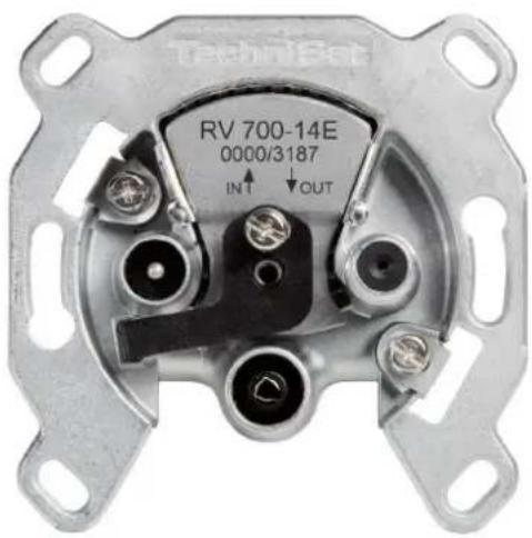
Fig. 1: RV 700-14E
| RV 700-8E End | outlet, terminated |
| RV 700-10E Loop through outlet 10 dB | |
| RV 700-14E Loop through outlet 14 dB | |
| RV 700-17E Loop through outlet 17 dB | |
— configured for single-cable systems according to EN 50494 and EN 50607
— All user bands (UB1 ... UB32) are enabled.
— LED display switched off
- Connections:
— TV: IEC connector (m) (IEC 61169-2)
— Radio: IEC connector (f) (IEC 61169-2)
— SAT: F-socket (IEC 61169-24)
- With screw and claw fastening for flush-mounted installation boxes ∅ 55 - 65 mm
2 Functional Specification
In single-cable satellite reception systems, interferences are possible if individual subscribers or receivers block the trunk line by means of an 18 V constant signal. Due to these interferences, other subscribers are no longer able to communicate with the multi-switch or LNB.
In practice, it is also possible that incorrectly configured receivers use the user IDs of other subscribers. In this case, we are talking about interferences in the form of the so-called ping-pong effect, because two subscribers "fight" for the same transponder.
The single-cable outlets of the RV 700-E series have a microcontroller that monitors signalling inside single-cable systems. In addition to signal voltages (14 V/18 V), audio signals (22 kHz) or DiSEqC ^™ signals are also analysed.
The antenna outlets turn off a permanent voltage of 18 V and, by means of a user ID check, ensure that only the enabled user band IDs are transmitted from the receiver to the multi-switch via the outlet.
The PROGRAMMING UNIT RVP 700 transmits the user band IDs which need to be enabled to the single-cable antenna outlet, thus ensuring that the subscribers in a single-cable antenna system do not interfere with each other. Using the PROGRAMMING UNIT RVP 700, a specialist retailer or installer configures one or several defined user IDs in the single-cable antenna outlet during the installation of the antenna system. To do so, the specialist retailer or installer connects the programming device to the F-socket of the antenna outlet. By means of the TechniSat RV-control app, a connection to the PROGRAMMING UNIT is established, and the data for the configuration of the antenna outlet is transmitted to the programming device.
3 Notes for the Installer
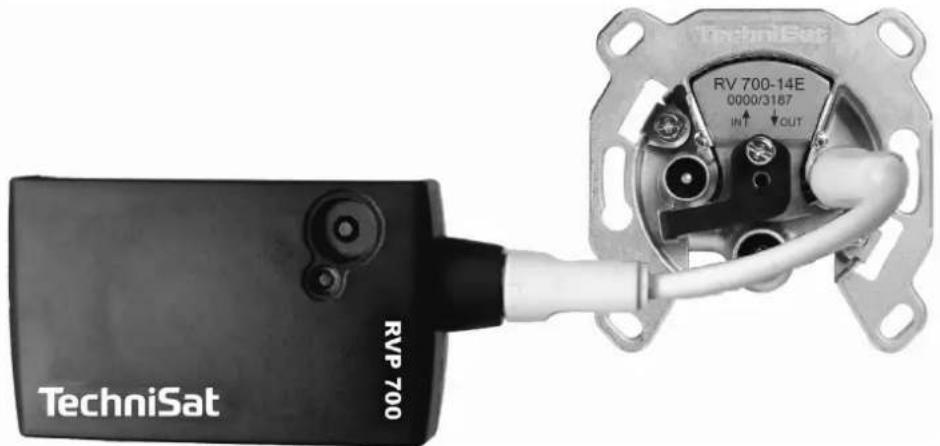
- To adjust other functions, the PROGRAMMIERADAPTER RVP 700 (item number 0000/3189) and the TechniSat RVcontrol app – available for free for various operating systems – are required; see Fig. 2.
- Pay attention to the RVP 700 and TechniPro RV 700 E user guide.
- To configure a single-cable outlet according to the antenna system layout, connect the RVP 700 to the SAT connection (F-type connector) of the outlet and follow the instructions in the RVP 700 and TechniSat RVcontrol app. You can do it either before or after the outlet has been installed in the system.
• We recommend keeping records of the enabled user band IDs of the outlet for the user. - When configuring an outlet, never do not disconnect it from the RVP 700 or interrupt the convection.
- Follow the installation instructions below to install the outlet.
natural_image
Close-up of a TechniSat RVP 700 sensor module connected to an electrical terminal block (no visible text or symbols on the device body)Fig. 2: PROGRAMMING UNIT RVP 700 connected to RV 700-14E.
4 Installation
4.1 Tools
- Knife or stripping aid
• Phillips screwdriver, size 1 or flat screwdriver 5 x 0.8
4.2 Installation and Safety Instructions
EN

WARNING
Risk of injuries due to sharp edges!
▶ Ensure that the installation is carried out by qualified personnel only.
▶ Use outlets indoors in dry areas only.
▶ Make sure not to damage the outer conductor when stripping it, otherwise the specified screening factors cannot be achieved.
▶ Make sure that the wires of the braided shield do not touch the inner conductor after stripping the cable. Danger of short circuit!
▶ Do not touch the tips of the claws.
4.3 Installing the Outlet
- Strip the cable as shown below.
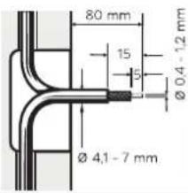
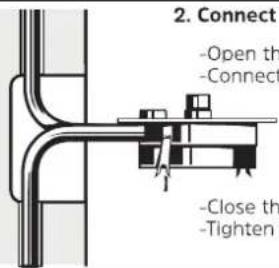
- Connect the cable. To do so:
-Open the flap..
-Connect the inner conductor.
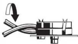
- Turn the outlet with cabel by 180°.
natural_image
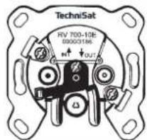
Pure electrical circuit lines without any symbols- Press the outlet into the installation box and lock it.
4.4 Service LED
| Display Function | |
| Red 18 V or 22 kHz signal at the satellite connection >400 ms (single-cable mode) | |
| Red Load current is too high; >500 mA (electronic fuse) | |
| Red, flashing DiSEqC ^TM command with a disabled user band ID from the end device at the satellite connec-tion | |
| Green Configurat on is being applied (programming mode). | |
| Green, flashing D ^TM SEqC command with an enabled user band ID | |
5 Technical Data
| Typ | RV 700-8E RV | 700-10E RV 700 | 0-14E RV 700-17E | |||
| Item number | 0000/3192 00 | 00/3186 0000/3187 | 0000/3188 | |||
| Through loss | 5 ... 10 MHz | - | 1,5 dB | 1,5 dB | 1,5 dB | |
| 10 ...862 MHz | - | 1,1 dB | 1,1 dB | 1,1 dB | ||
| 862 ... 2.150 MHz | - | 1,9 dB | 1,9 dB | 1,9 dB | ||
| Insertion loss | TV | 5...68 / 118...862 MHz | 8 dB | 10 dB | 14 dB | 17 dB |
| SAT | 950 ... 2.150 MHz | 8 dB | 10 dB | 14 dB | 17 dB | |
| Radio | 87,5 ... 108 MHz | 9 dB | 11 dB | 15 dB | 18 dB | |
| Decoupling(Between two subscribers) | 5 ... 862 MHz | - | ≥42 dB | |||
| 950 ... 2.150 MHz | - | ≥32 dB | ||||
| Screening factor | 5 ... 300 MHz | ≥85 dB | ||||
| 300 ... 470 MHz | ≥80 dB | |||||
| 470 ... 950 MHz | ≥75 dB | |||||
| 950 ... 2.150 MHz | ≥55 dB | |||||
| Compliant with standards | EN 60728-11, EN 50083-2 | |||||

Please dispose of the device at the end of its service life in accordance with legal regulations, e.g. return the device to public collection points.
Please contact your local council to find out where your nearest disposal facility is.
Your product carries the CE-sign and fulfills all nessecary requirements form the EU.
Changes and misprints excepted. Status 09/16
Copy and reproduction only with approval of the publisher.
TechniSat is a registered trademark of

Brand : TECHNISAT
Model : TECHNIPRO RV 700-8E
Category : Uncategorized