
TechniNet BS4 - Uncategorized TECHNISAT - Free user manual and instructions
Find the device manual for free TechniNet BS4 TECHNISAT in PDF.


| Product Type | Broadband Router/Modem |
| Brand | TechniSat |
| Model | TechniNet BS4 |
| Dimensions (approx.) | 200 x 150 x 40 mm |
| Weight (approx.) | 300 g |
| Power Supply | 12 V DC, 1 A |
| Wireless Standards | IEEE 802.11 b/g/n |
| Frequency Band | 2.4 GHz |
| WAN Port | 1x RJ45 (Ethernet) |
| LAN Ports | 4x RJ45 (Gigabit Ethernet) |
| USB Port | 1x USB 2.0 |
| Antenna | 2x external (detachable) |
| Security | WPA/WPA2, WEP, SPI Firewall |
| Indicators | Power, Internet, LAN, WLAN |
| Maintenance | Clean with dry cloth; keep ventilated |
| Spare Parts | Power adapter, antennas (available separately) |
| Repairability | No user-serviceable parts; contact support |
Frequently Asked Questions - TechniNet BS4 TECHNISAT
User questions about TechniNet BS4 TECHNISAT
0 question about this device. Answer the ones you know or ask your own.
Ask a new question about this device
Download the instructions for your Uncategorized in PDF format for free! Find your manual TechniNet BS4 - TECHNISAT and take your electronic device back in hand. On this page are published all the documents necessary for the use of your device. TechniNet BS4 by TECHNISAT.
USER MANUAL TechniNet BS4 TECHNISAT
3.1 Wandmontage....8
3.2 19 Zoll Schrankmontage....8
3.3 Erdung....8
natural_image
Top-down view of a printed circuit board with various electronic components and traces (no visible text or symbols)01:QPSK->PAL A Tuner Lock:Yes RF Frq:140,25MHz P010,010,110,100
01:QPSK->PAL A Tuner Lock:Yes RF Frq:140,25MHz P010,010,110,100
natural_image
Top-down view of a printed circuit board with various electronic components and connectors (no visible text or symbols)02:QPSK->QAM A
Tuner Lock:Yes
RF Frq:330,0MHz
P010,010,110,103
02:QPSK->QAM A
Tuner Lock:Yes
RF Frq:330,0MHz
P010,010,110,103
| 02:QPSK->QAM | A |
| Tuner Lock:Yes | |
| RF Frq:330,0MHz | |
| P010,010,110,103 |
natural_image
Overhead view of a computer motherboard showing various electronic components and circuit boards (no visible text or labels)8 bit pro Symbol [bei 256-QAM]
EC-Declaration of Conformity

marking
We, Manufacturer/Importer
(full address)
declare that the product
description of the apparatus, system, installation to which it refers)
Kabelkopfstation
TechniNet BS 4
Brand: TechniSat
is in conformity with
Council Directive 2004/108/EC (EMC Directive)
Standards to which conformity is declared:
EN50083-2.2005
Cable networks for television signals, sound signals and interactive services - Part 2: Electromagnetic compatibility for equipment
EN55022:2006+A1:2007
Information technology equipment - Radio disturbance characteristics - Limits and methods of measurement
EN55024.1998+A1:2001+A2:2003
Information technology equipment - Immunity characteristics - Limits and methods of measurement
EN61000-3-2:2006
Electromagnetic compatibility (EMC) - Part 3-2: Limits - Limits for harmonic current emissions (equipment input current up to and including 16A per phase)
EN61000-3-3:2008
Electromagnetic compatibility (EMC) - Part 3-3: Limits: Limitation of voltage changes, voltage fluctuations and flicker in public low-voltage supply systems, for equipment with rated current up to 164 per phase
▶ please note reverse side
TechniSat
Digital GmbH
TechniPark
D-54850 Daun/Vulkaneifeil
(Stamp)
Manufacturer/Importer
Date:
25.10.2010
Signature:
Name:

Stephan Schaaf

TESTED IN GERMANY
Date: 15.09.2010 Ref.-No.: 10/09-0049 Based on Test-Report, Ref.-No.: 10/09-0049
ACCREDITATIONS: - ISO/IEC17025.2005 - KBA-P 00088-96
pkm elektronjc GmbH
DE
P. O. box 560, D-54541 Daun/Vulkaneifel (Germany)
All rights reserved,
including those relating to photomechanical reproduction and storage on electronic media.
We have made every effort to ensure that all the product information on these pages is current, complete and accurate. Nevertheless we draw your attention to the following:
-
TechniSat accepts no warranty for the information in the contents, specifically with regard to its currency, accuracy or completeness. The product descriptions contained herein are merely illustrative of the features and are categorically not assurances or guarantees of their qualities. We expressly reserve the right to make changes to products at any time in terms of colour and design, including technical changes - without prior notification where necessary.
-
Liability claims against TechniSat arising from the use of erroneous or incomplete information or product descriptions are excluded, in so far as there is no proven intentional or grossly negligent behaviour on the part of TechniSat.
CE
Content
1 Safety instructions....46
2 Description....48
2.1 TechniNet BS4 (0000/5960) base unit....48
2.2 Explanation of controls....49
3 Implementation....50
3.1 Wall mounting....50
3.2 19" rack mounting....50
3.3 Earthing....50
3.4 Connecting the power supply 50
3.5 Connecting the SAT IF inputs and outputs.... 51
3.5.1 Connecting the HF outputs....51
3.5.2 Connecting the LAN....51
3.6 Implementing the SkyCable TWIN cards....52
3.6.1 Levelling the head station....53
3.7 Installation example....54
3.8 Programming remote control (0000/5961).... 55
3.9 SkyCable 8PSK/PAL CI TWIN card (0000/5962)....56
3.9.1 Brief description....56
3.9.2 Programming the SkyCable 8PSK/PAL CI TWIN card....57
3.10 SkyCable DVB-S2/QAM CI TWIN card (0000/5963)....62
3.10.1 Brief description....62
3.10.2 Programming the SkyCable DVB-S2/QAM CI TWIN card....63
3.10.3 Network Information Table (NIT) 67
3.11 SkyCable DVB-S2/DVB-T CI TWIN card (0000/5964)....68
3.11.1 Brief description....68
3.11.2 Programming the SkyCable DVB-S2/DVB-T CI TWIN card....69
3.11.3 Network Information Table (NIT) 73
4 Technical data....74
4.1 Base unit (0000/5960)....74
4.2 SkyCable 8PSK/PAL CI TWIN card (0000/5962)....75
4.3 SkyCable DVB-S2/QAM CI TWIN card (0000/5963)....76
4.4 SkyCable DVB-S2/DVB-T CI TWIN card (0000/5964)....77
5 Helpful information....78
5.1 DVB-S data rate....78
5.2 DVB-S2 data rates....78
5.3 DVB-T data rates....78
5.4 DVB-C data rates....79
5.5 Channel / Frequency conversion table (BC grid) 80
5.6 Level parameters for internal distribution networks....81
6 Accessoires....81
7 Declaration of Conformity 82
1 Safety instructions
For your own protection you should read the safety notes carefully before using the device.
All assembly and installation work should be carried out by an expert. Experts are individuals with extensive knowledge, based on training and experience, in the area of satellite equipment installation and who are familiar with relevant national occupational safety and accident prevention regulations, guidelines and generally recognised technology rules (e.g. VDE specifications, DIN standards), to the extent that they are able to assess conditions of occupational safety. Adherence to the relevant local assembly and installation specifications and regulations is a prerequisite for assembling this satellite reception equipment.
The manufacturer accepts no liability for damage caused by inappropriate handling, non-compliance with safety precautions or use of system accessory components that are not original or approved.
In the following circumstances you should disconnect the device from the mains power and consult an expert:

⇒ the power cable or mains plug is damaged
⇒ the device has been exposed to moisture or liquid has got into it
⇒ there are significant malfunctions
⇒ there is severe external damage.

natural_image
Illustration of a computer monitor with a switch and warning symbol (no text or labels)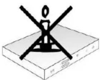
natural_image
Simple line drawing of a device with a cross symbol above it, no text or labels present.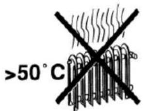


natural_image
Simple black cross symbol on white background with radiating lines (no text or numbers)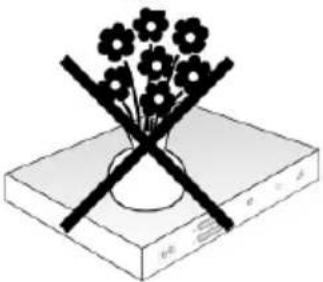
natural_image
Illustration of a vase with flowers crossed over a book, no text or symbols presentDanger and installation instructions of particular note:
⇒ The construction of the product corresponds to protection class 1. Only a properly working power socket (with earth wire) connected to the mains power supply should be used as a source of power (230V\~/50Hz).
⇒ The plug for the power cable should always be easily accessible and be ready to be used correctly.
⇒ The permitted ambient temperature is 0-45°C.
Only use the device indoors, to protect it from lightning, rain and solar radiation. The device should only be installed in rooms where the permitted ambient temperature range can be maintained even when the climatic conditions change (excluding radiated heat and other sources of heat).
⇒ The device should not be exposed to spray or water droplets.
⇒ Do not place any objects filled with water on the device.
⇒ Do not place any burning objects such as candles on the device.
⇒ Only mount on vertical surfaces.
⇒ Ensure that the ventilation slits are not covered by objects such as newspapers, tablecloths, curtains etc.
⇒ Ensure the device has good ventilation.
⇒ If condensation should form, wait until the device is completely dry.
To be observed in all situations:
DIN VDE regulations 0701, sections 1 and 200.
⇒ EN 50 083 - section 1 “Cabled distribution systems for television and sound signals”
Section 1: Safety requirements.
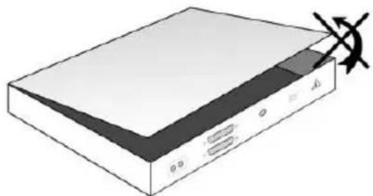
⇒ The device is only to be opened by authorised specialists (certified experts).
⇒ Ensure that only replacement parts recommended by the manufacturer or parts that are of a construction identical to the originals are used. Use of unsuitable spare parts can cause further damage to the device.
For your safety:

⇒ Observe the above regulations and instructions.
Set the satellite device up in accordance with the safety requirements.
⇒ Observe the provisions regarding earthing and potential equalisation.
Please observe all safety instructions at all times!
2 Description
2.1 TechniNet BS4 (0000/5960) base unit
The TechniNet BS4 Professional is a base unit that accepts SkyCable TWIN cards for professional satellite signal processing. The eight slots for eight TWIN cards, professional power supply with safety features, and numerous connection options enable this head station to fulfil every conceivable usage scenario.
The inbuilt 4/16 multi-switch saves expensive internal cabling in the base unit and provides four fully-functional satellite inputs that generate both 13/18V and 0/22 kHz signals for controlling the LNB. This gives the receiver cards unlimited access to all four IF levels. Naturally, the system also has inputs and outputs for SAT IF signals, enabling these signals to be distributed from one base unit to another in cascade mode.
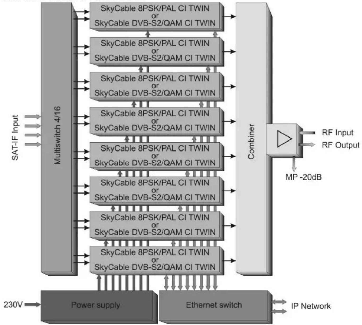
flowchart
graph TD
    A["SAT-IF Input"] --> B["Multiswitch 4/16"]
    B --> C["Power supply"]
    C --> D["Ethernet switch"]
    D --> E["Combiner"]
    E --> F["RF Input"]
    E --> G["RF Output"]
    E --> H["MP -20dB"]
    B --> I["SkyCable 8PSK/PAL CI TWIN or SkyCable DVB-S2/QAM CI TWIN"]
    B --> J["SkyCable 8PSK/PAL CI TWIN or SkyCable DVB-S2/QAM CI TWIN"]
    B --> K["SkyCable 8PSK/PAL CI TWIN or SkyCable DVB-S2/QAM CI TWIN"]
    B --> L["SkyCable 8PSK/PAL CI TWIN or SkyCable DVB-S2/QAM CI TWIN"]
    B --> M["SkyCable 8PSK/PAL CI TWIN or SkyCable DVB-S2/QAM CI TWIN"]
    B --> N["SkyCable 8PSK/PAL CI TWIN or SkyCable DVB-S2/QAM CI TWIN"]
    B --> O["Combiner"]
    O --> P["IP Network"]
    style A fill:#f9f,stroke:#333
    style B fill:#ccf,stroke:#333
    style E fill:#cfc,stroke:#333
    style P fill:#fcc,stroke:#333
Image: Block diagram for TechniNet BS4 base unit
This top-quality switching mode power supply with constant ventilation ensures that sufficient power is available and protects against high temperatures and current loads. 3 temperature-controlled fans are incorporated in the housing to improve thermal stability for the components by removing the hot air from the housing.
The base unit can be controlled using the programming remote control via a cable connection. In addition, there is the option of using an Ethernet connection to enable programming over the LAN via a laptop with a GUI.
The TWIN card output signals are fed over the preinstalled collection area and boosted via the integrated hybrid amplifier to an output level of up to 107dBμV.
The base unit HF outputs can be cascaded. However, to reduce the system noise power it is often advantageous to feed the output signals for multiple base units via an external diplexer and feed them into the existing cable network.
The flexible mounting system supplied allows the base unit to be mounted on a wall or on a professional 19" rack.
2.2 Explanation of controls
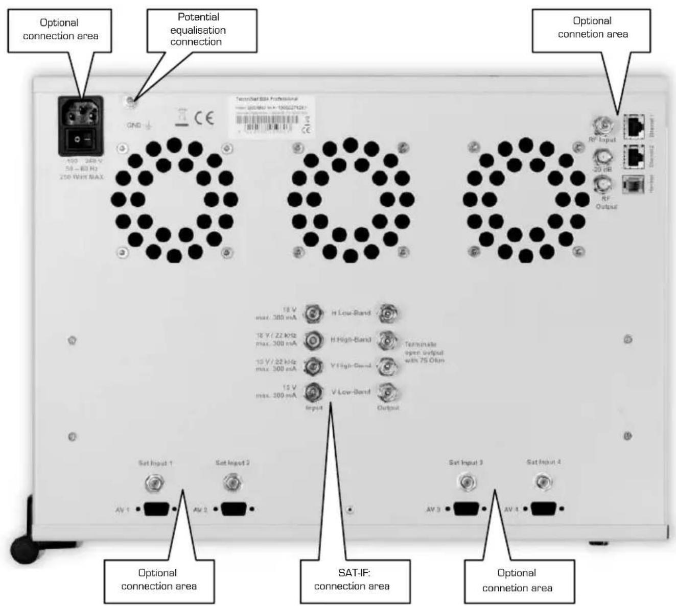
Image: Top view of TechniNet BS4 base unit
3 Implementation
The following prerequisites must be followed to prepare the TechniNet BS4 head station for use:

- Appropriate experience in constructing cable head stations and satellite reception equipment.

- Access to a professional digital measuring device with the following features:
- Level measurement in dBμV.
• C/N measurement in dB for PAL signals. - Bit error rate (BER) measurement for QAM signals.
- Modulation error rate (MER) measurement for QAM signals.
- Spectrum analysis.
The head station should be mounted in rooms where the permitted ambient temperature (0-45°C) can safely be maintained.
Please observe the safety instructions in section 2 at all times.
3.1 Wall mounting
Use four screws to attach the base unit to the two pre-mounted angle brackets against a firm, non-flammable background.
Ensure there is clearance of at least 20cm above the base unit. Never cover the ventilator air output slits.
3.2 19" rack mounting
To mount on a 19" rack, remove the angle brackets supplied from the back of the base unit and mount them on the front of the housing. Now mount the base unit onto a 19" rack using additional fixing brackets in the 19" rack. Ensure there is a clearance of at least 20cm above the base unit.
3.3 Earthing
Carry out potential equalisation on the head station in accordance with regulations and observe the relevant provisions of EN 50083-1/EN 60728-11 at all times. Connect the head station PA connector to the PA equalising bar via a copper wire of at least 4mm^2 (green/yellow).
3.4 Connecting the power supply
Connect the base unit low heat socket to a properly functioning mains socket (230V\~/50Hz) using the mains cable supplied.
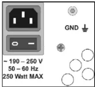
This enables you to switch on the TechniNet BS4 base station via the mains switch. The device is immediately ready for use.
Only use the original mains cable supplied.
Image: Power supply connection area
3.5 Connecting the SAT IF inputs and outputs
Always use your professional measuring device to check the SAT IF signal quality and ensure that the signal levels are within the input level range of the multi-switch. The level should be approx. 80 dBμV.
Attach the SAT IF cables to the appropriately marked inputs on the base units and check whether potential equalisation needs to be carried out on the coaxial cable.
The maximum LNB remote feed current is 300mA per input and is short-circuit-proof.
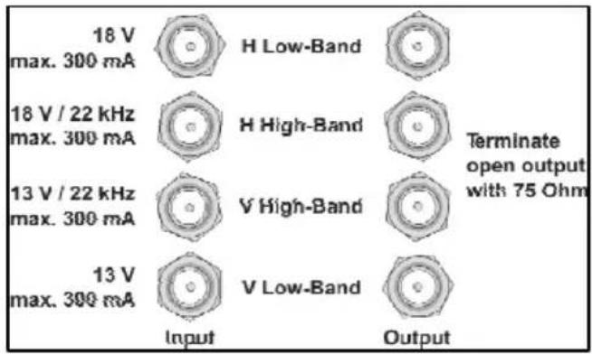
Image: SAT IF connection area
The outputs are used to loop the SAT IF signals through to another base unit. Cascading more than two devices is not recommended because of the increase in level difference in the input signal. Unused SAT looping outputs must be terminated using the enclosed terminal resistors.
3.5.1 Connecting the HF outputs
The integrated collection area in the TechniNet BS4 base unit switches the 16 channel strips to the HF output. Attach the CATV network coaxial cable to the RF output port on the base unit and check whether potential equalisation needs to be carried out on the coaxial cable.
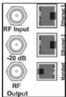
Image: HF outputs connection area
The RF input port is used for cascading an additional BS4. To do this, connect the RF output for the second BS4 to the input for the first. Cascading more than two devices is not recommended because of the increase in system noise power. It is better to feed the output signals from a third BS4 base unit via an external diplexer.
If the RF input port is not being used, it must be terminated with a 75 ohm terminal resistor at all times.
3.5.2 Connecting the LAN
You can use the Ethernet LAN ports to configure and control the TechniNet BS4 base unit via a graphic user interface on a PC. To do this, connect the PC to the Ethernet 1 port on the BS4 using a network cable.
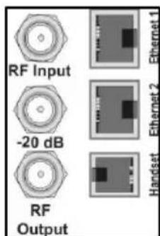
Image: LAN connection area
To network additional base units, use the Ethernet 2 port on the BS4. To do this, connect the Ethernet 2 port on the first BS4 to the Ethernet 1 port on the second BS4 and so on. The subnet mask sets a volume limit.
3.6 Implementing the SkyCable TWIN cards
After you have installed all the connection cables on the base unit, the SkyCable TWIN cards are installed. Before you insert cards into the TechniNet BS4 base station, always switch them to zero potential.
Please note:
When handling SkyCable cards, ESD protection measures in accordance with DIN 100 015-1 must be observed (create potential equalisation between the body and the earth of the device and housing via high-impedance resistance (c. 1 mohm) e.g. using a standard ESD wrist strap).
After you have opened the door of the base unit, the slots for the SkyCable cards will be visible. Slot 1 is located on the left and slot 8 on the right of the base unit.
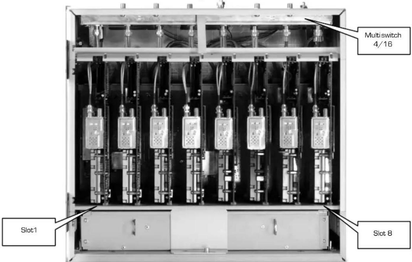
Picture: Base station TechniNet BS4 Professional, equipped
Now insert the cards into the slots one at a time and connect the tuner coaxial cables to the multi-switch F-jack. The coaxial connections for unused slots must be closed off using 75 ohm resistances. When all the cards have been installed, you can reconnect the base unit to the mains.
Now program the cards using the programming remote control or the PC software (TMS), if you are a trained expert. You can find details on how to use the programming remote control for the setup in the following sections.
3.6.1 Levelling the head station
When you have finished configuring all the cards, connect your professional measuring device to the base unit operating output and adjust the output levels of all the channels to the correct level setting, as in the following diagram.
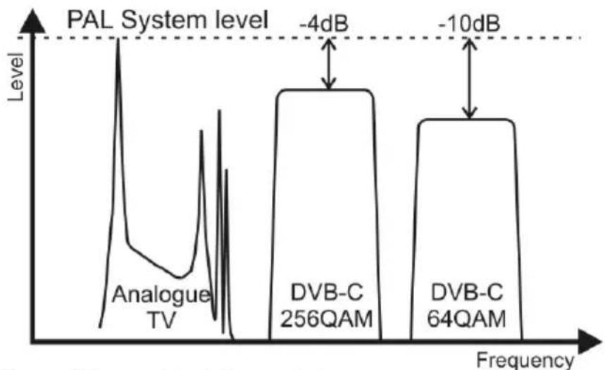
line
| System | Level Label | | ---------------- | ----------------- | | Analogue TV | -4dB | | DVB-C 256QAM | -4dB | | DVB-C 64QAM | -10dB |Image: BC network level characteristics
Adjust all the signal parameters related to performance e.g. C/N (PAL), MER and BER (QAM) to the quality you want and log them.

Observe the permitted useful signal level in the internal distribution network as described in section 6.3 at all times.
3.7 Installation example
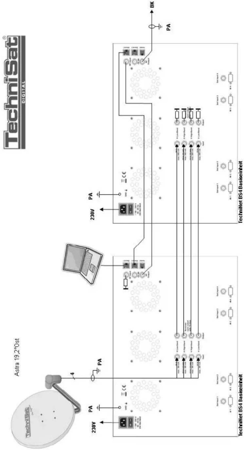
flowchart
graph TD
    A["Astra 19,2°0st"] --> B["TechniSat"]
    B --> C["4"]
    C --> D["PA"]
    D --> E["230V"]
    E --> F["Output"]
    G["TechniNet BS4 Basiseinheit"] --> H["Sub-Input 1: A1, A2, A3"]
    G --> I["Sub-Input 2: A1, A2, A3"]
    G --> J["Sub-Input 3: A1, A2, A3"]
    G --> K["Sub-Input 4: A1, A2, A3"]
    L["TechniNet BS4 Basiseinheit"] --> M["Sub-Input 1: A1, A2, A3"]
    L --> N["Sub-Input 2: A1, A2, A3"]
    L --> O["Sub-Input 3: A1, A2, A3"]
    P["TechniNet BS4 Basiseinheit"] --> Q["Sub-Input 1: A1, A2, A3"]
    P --> R["Sub-Input 2: A1, A2, A3"]
    P --> S["Sub-Input 3: A1, A2, A3"]
3.8 Programming remote control (0000/5961)
The cable-connected programming remote control - or programmer for short - is used for configuring the SkyCable TWIN cards. The programmer is connected to the 'Handset' port on the TechniNet BS4 base unit via the supplied cable. This enables the SkyCable cards to be configured.
EN
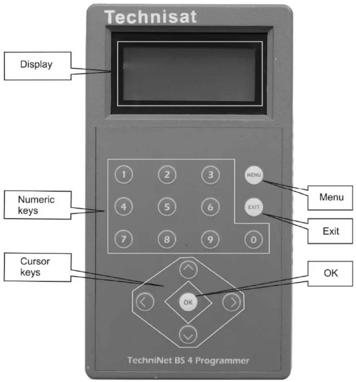
Image: Programming remote control (0000/5961)
3.9 SkyCable 8PSK/PAL CI TWIN card (0000/5962)
3.9.1 Brief description
The 8PSK/PAL CI TWIN card is used to demodulate two QPSK or 8PSK satellite signals in MPEG-2, enabling them to then be processed into two analogue PAL signals for the 100 MHz to 860 MHz frequency range. The use of a CA module with a suitable Smartcard also allows the channels to be decoded directly on the card.
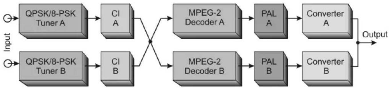
flowchart
graph LR
    A["Input"] --> B["QPSK/8-PSK Tuner A"]
    A --> C["QPSK/8-PSK Tuner B"]
    B --> D["CI A"]
    C --> E["CI B"]
    D --> F["MPEG-2 Decoder A"]
    E --> G["MPEG-2 Decoder B"]
    F --> H["PAL A"]
    G --> I["PAL B"]
    H --> J["Converter A"]
    I --> K["Converter B"]
    J --> L["Output"]
    K --> L
Image: SkyCable 8PSK/PAL CI TWIN card functional diagram
This card can only be operated in the TechniNet BS4 base unit as it does not have its own power supply or control panel and cannot supply voltage to an LNB. Operating and controlling the card is only possible via the programmable remote control or a special PC software application.
natural_image
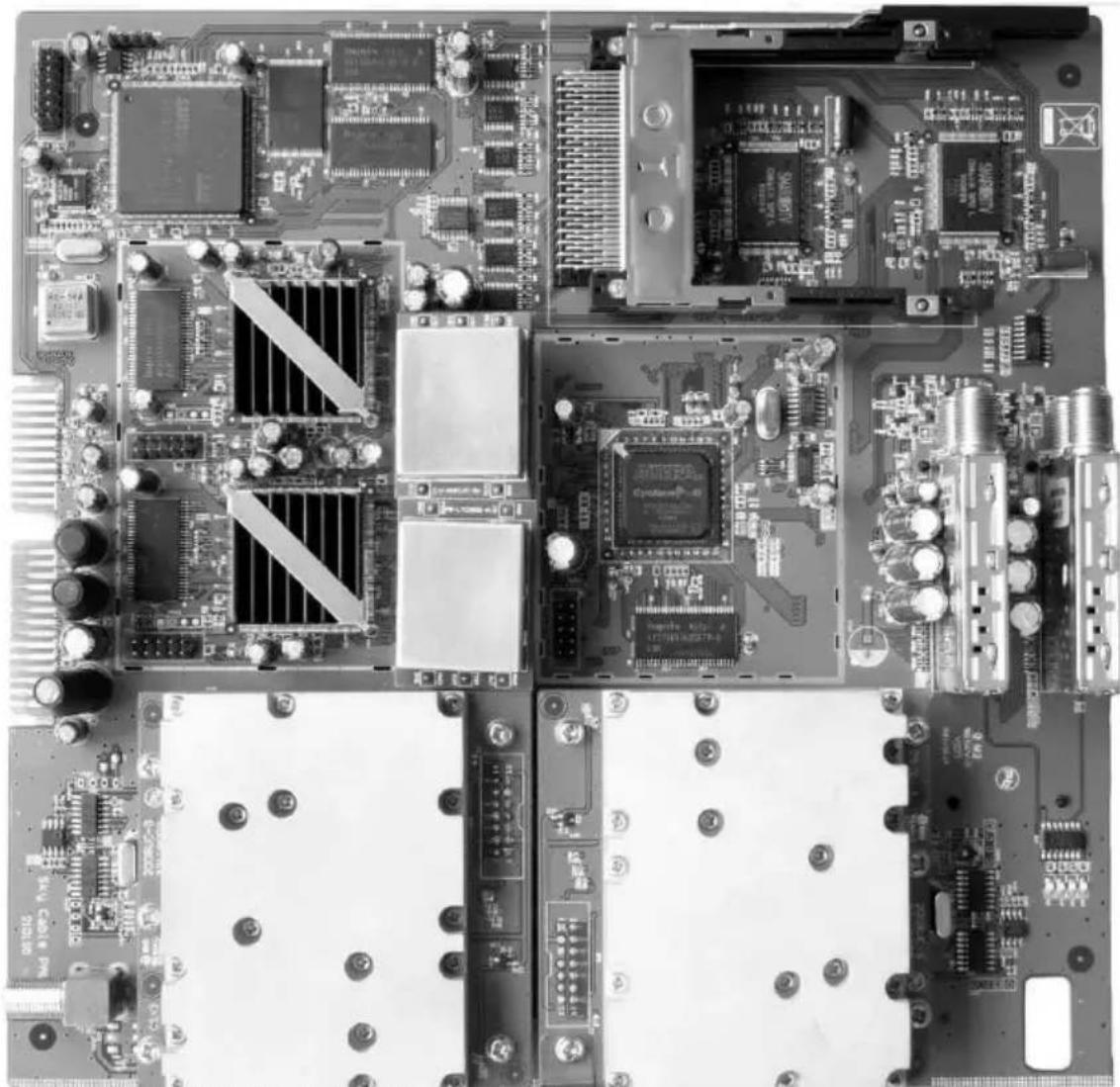
Top-down view of a printed circuit board with various electronic components and traces (no visible text or symbols)Image: SkyCable 8PSK/PAL CI TWIN card [0000/5962]
3.9.2 Programming the SkyCable 8PSK/PAL CI TWIN card
The following description explains how to program a SkyCable 8PSK/PAL CI TWIN card using the programming remote control.
The programmer is connected to the 'Handset' port on the base unit via the supplied cable. The following message appears in the programmer display:
3.9.2.1 Display Start
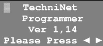
After pressing the cursor button ▶ the settings for card slot 01 are displayed; those for card slot 08 are displayed by pressing ◀. The other slots can be selected by pressing the cursor buttons again. The numbering of the slots goes upwards from left to right.
3.9.2.2 Display Line 1
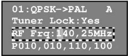
01:QPSK->PAL A Tuner Lock:Yes RF Frq:140,25MHz P010,010,110,100
Select the card slot as described in 3.9.2.1.
The flashing cursor indicates the selected card slot [O1] and type (QPSK->PAL). Press the Menu button to toggle between the two receiving units A and B.
01:QPSK->PAL A Tuner Lock:Yes RF Frq:140,25MHz P010,010,110,100
Pressing the ▼ or ▲ cursor button moves the flashing cursor to another line. In this line you can call up additional menu items by pressing the Menu button.
3.9.2.3 Display Line 2
01:QPSK->PAL A Tuner Lock:Yes RF Frq:140,25MHz P010,010,110,100
Select line 2 as described in 3.9.2.2.
If the flashing cursor is located in the second line the following sub-items can be called up by repeatedly pressing the Menu button:
| 1. Tuner Lock: Yes | = Input signal OK |
| 2. Sat Frq:11954MHz | = Satellite downlink frequency |
| 3. Sat SR:27500KB | = Symbol rate |
| 4. LNB Frq:10600MHz | = LNB local oscillator frequency (LO) |
| 5. LNB Set:18V/22kHz | = Multi-switch control |
| 6. CI:No Module | = CAM type |
| 7. CI:Program | = CAM program selection |
| 8. Decoder:TS-A | = Tuner selection |
| 9. Pg: -No 28007 | = Output program selection |
| 10. Screen:16:9 Full | = Picture format |
| 11. ScreenMode:Auto | = Television standard |
| 12. Audio Lang: none | = Language selection |
| 13. Subtitle:DVB 1st | = Teletext |
1. Tuner Lock: Yes
Input signal OK
No selection option, just a display showing whether the satellite tuner is synchronised with the input signal.
| Yes | = | Tuner is synchronised. |
| No | = | Tuner is not synchronised. |
| 2. Sat Frq:11954MHz | Satellite downlink frequencyThe frequency input is entered in MHz using the numeric buttons.The data is transferred when the OK button is pressed. | |
| 3. Sat SR:27500KB | Symbol rateThe symbol rate is entered in baud using the numeric buttons.The data is transferred when the OK button is pressed. | |
| 4. LNB Frq:10600MHz | LNB local oscillator frequency [LO]The LO frequency is entered in MHz using the numeric buttons and depends on the satellite frequency range.→ Low band from 10.70-11.70 GHz ≦ LO = 9750 MHz→ High band from 11.70-12.75 GHz ≦ LO = 10600 MHzThe data is transferred when the OK button is pressed. | |
| 09750MHz | = LO frequency for low band | |
| 10600MHz | = LO frequency for high band | |
| 5. LNB Set:18V/22kHz | Controlling the integrated multi-switchPress the ▶ or ▶ cursor button to set the control voltage for the integrated multi-switch and hence select the SAT IF level. The data is transferred when the OK button is pressed after selection. | |
| 13V/ OK | = Vertical low band | |
| 18V/ OK | = Horizontal low band | |
| 18V/22K | = Horizontal high band | |
| 13V/22K | = Vertical high band | |
| 6. CI:No Module | CAM typeDisplays the designation of an available CAM. If no CAM is available the message “No Module” appears. | |
| 7. CI:Program | CAM program selectionHere you can select which of the programs available in the reception signal are unlocked by the smart card. Only functions when a CAM is available. | |
| 8. Decoder:TS-B | Tuner selectionPress the ▶ or ▶ cursor button to select which transport stream (TS) from which tuner input is used for the modulator. The data is transferred when the OK button is pressed after selection. | |
| TS-A | = Transport stream from Tuner A | |
| TS-B | = Transport stream from Tuner B | |
| 9. Pg:F -No 28007 | Output program selectionThis menu item is used to define which program is converted into PAL. Press the ▶ or ▶ cursor button to select the program you want. The data is transferred when the OK button is pressed. | |
| 10. Screen:16:9 Full | Picture formatPress the ▶ or ▶ cursor button to select the picture format setting. The data is transferred when the OK button is pressed alter selection. | |
| 16:9 Full | = 16:9 picture format | |
| 4:3 Full | = 4:3 picture format | |
| 4:3 LB | = 4:3 letterbox picture format | |
| 11. ScreenMode:Auto | Television standardPress the ▶ or ▶ cursor button to select the picture format setting.The data is transferred when the OK button is pressed alter selection. | |
| Auto | = Automatic | |
| PAL | = PAL standard | |
| NTSC | = NTSC standard | |
| SECAM | = SECAM standard | |
| 12. Audio-Lang:none | Language selectionIf multiple languages are available for the program in the transport stream, you can select the language that is modulated to the sound carrier here. | |
| 13. Subtitle:DVB 1st | TeletextPress the ▶ or ▶ cursor button to select the teletext setting. The data is transferred when the OK button is pressed after selection. If both standards are available in the signal, only the selected version is forwarded | |
| DVB 1st | = Teletext as per DVB standard | |
| EBU 1st | = Teletext as per EBU standard, teletext level 1 | |
| 3.9.2.4 Display Line 3 | Select line 3 as described in 3.9.2.2. | |
 | If the flashing cursor is located in the third line the following sub-items can be called up by repeatedly pressing the Menu button: | |
| 1. RF Frq:112,25MHz | = Output frequency | |
| 2. RF Attn:00dB | = Output level attenuation | |
| 3. Audiomode:Stereo | = Sound carrier mode | |
| 4. Volume:70 | = Audio level | |
| 1. RF Frq:112,25MHz | RF output frequencyThe frequency output is entered in MHz using the numeric buttons. This is the picture carrier frequency in PAL signals. The correct frequencies can be taken from the table in section 5.5.The data is transferred when the OK button is pressed. | |
| 2. RF Attn:00dB | RF T-pad attenuatorThe attenuation value for the output level is entered using the numeric buttons. 9dB max can be set.The data is transferred when the OK button is pressed.Watch the linearity of the wanted signal level for all the TWIN cards and adjust the output level by setting it to the RF T-pad attenuator, while watching the level parameters (see 5.6). | |
| 3. Audiomode:Stereo | Sound sub-carrier modePress the ▶ or ▶ cursor button to set the sound sub-carrier to stereo, mono or dual sound.The data is transferred when the OK button is pressed. | |
| 4. Volume:70 | Audio levelThe audio level is entered using the numeric keys. The value affects the FM hub and hence the volume.The data is transferred when the OK button is pressed. | |
3.9.2.5 Display Line 4
Select line 4 as described in 3.9.2.2.
01:QPSK->PAL A
Tuner Lock:Yes
RF Frq:140,25MHz
P010,010,110,100
If the flashing cursor is located in the fourth line the following sub-items can be called up by repeatedly pressing the Menu button:
| 1. P010,010,110,100 | = IP address | |
| 2. M255,255,255,000 | = Subnetzmaske | |
| 3. G010,010,060,001 | = Standardgateway | |
| 4. T000,010,070,066 | = SNMP trap destination IP address | |
| 5. MAC:000e26ff417b | = MAC address | |
| 6. Temperature:37°C | = Temperature | |
| 7. MainVer:28DM100a | = Firmware version | |
| 8. MCU Ver:4,f0,3f | = Software version | |
| 9. FPGA Ver:0,0,0b | = FPGA version | |
| 10. Factory Setting? | = Factory default setting | |
| 11. Reboot System? | = Reboot | |
| 1.P010,010,110,100 | IP addressThe IP address is entered using the numeric keys. The data is automatically transferred after all 12 digits have been entered. The IP address is required for controlling the head station via a PC and should only be allocated to the network once! |
| 2.M255,255,255,000 | Subnet maskThe subnet mask is entered using the numeric keys. The data is automatically transferred after all 12 digits have been entered. |
| 3.G010,010,060,001 | Standard gatewayThe standard gateway is entered using the numeric keys. The data is automatically transferred after all 12 digits have been entered. |
| 4.T000,010,070,066 | SNMP trap destination IP addressThe trap destination IP address is entered using the numeric keys. The data is automatically transferred after all 12 digits have been entered. |
| 5.MAC:000e26ff417b | MAC addressDisplays the card's MAC address. No selection options. |
| 6.Temperature:37°C | TemperatureDisplays the card temperature. No selection options. |
| 7.MainVer:28DM100a | Firmware versionDisplays the card's software version. No selection options. |
| 8.MCU Ver:4,f0,3f | Software versionDisplays the card's software version. No selection options. |
| 9.FPGA Ver:0,0,0b | FPGA versionDisplays the card's FPGA version. No selection options. |
| 10.Factory Setting? | Factory default settingPress the OK button to get the selection option:OK=Y ; EXIT=NConfirm by pressing OK and the entire card (receiving unit A and B) is reset to the factory default settings (Preset). All settings previouslymade are permanently deleted. Exit this option by pressing EXIT. The card only becomes operable again after the boot process is completed. |
| 11. Reboot System? | RebootPress the OK button to get the selection option:OK=Y ; EXIT=NConfirm with OK to reboot the card - exit this option by pressing EXIT.The card only becomes operable again after the boot process is completed. |
EN
3.10 SkyCable DVB-S2/QAM CI TWIN card (0000/5963)
3.10.1 Brief description
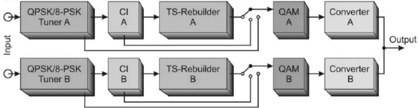
The DVB-S2/QAM CI TWIN card is used to demodulate two DVB-S2 satellite signals, enabling them to then be processed into two QAM signals for the 100 MHz to 860 MHz frequency range. The use of a CI module with a suitable Smartcard also allows the channels to be decoded directly on the card.
flowchart
graph LR
    A["Input"] --> B["QPSK/8-PSK Tuner A"]
    B --> C["CI A"]
    C --> D["TS-Rebuilder A"]
    D --> E["QAM A"]
    E --> F["Converter A"]
    F --> G["Output"]
    H["Input"] --> I["QPSK/8-PSK Tuner B"]
    I --> J["CI B"]
    J --> K["TS-Rebuilder B"]
    K --> L["QAM B"]
    L --> M["Converter B"]
    M --> G
Image: Image: SkyCable DVB-S2/QAM CI TWIN card functional diagram
This card can only be operated in the TechniNet BS4 base unit as it does not have its own power supply or control panel and cannot supply voltage to an LNB. Operating and controlling the card is only possible via the programmable remote control or a special PC software application.
natural_image
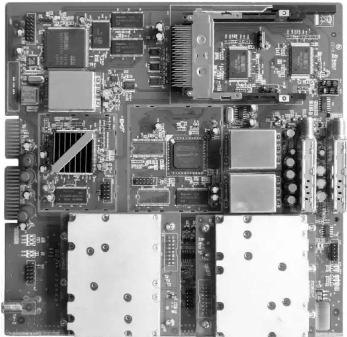
Top-down view of a printed circuit board with various electronic components and traces (no visible text or symbols)Image: SkyCable DVB-S2/QAM CI TWIN card (0000/5963)
3.10.2 Programming the SkyCable DVB-S2/QAM CI TWIN card
The following description explains how to program a SkyCable DVB-S2/QAM TWIN card using the programming remote control.
The programmer is connected to the 'Handset' port on the base unit via the supplied cable. The following message appears in the programmer display:
3.10.2.1 Display Start
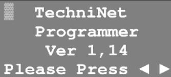
After pressing the cursor button ▶ the settings for card slot 01 are displayed; those for card slot 08 are displayed by pressing ◀. The other slots can be selected by pressing the cursor buttons again. The numbering of the slots goes upwards from left to right.
3.10.2.2 Display Line 1
02:QPSK->QAM A Tuner Lock:Yes RF Frq:330,0MHz P010,010,110,103
Select the card slot as described in 3.10.2.1
The flashing cursor indicates the selected card slot (02) and type (QPSK->QAM). Press the Menu button to toggle between the two receiving units A and B.
02:QPSK->QAM A Tuner Lock:Yes RF Frq:330,0MHz P010,010,110,103
Pressing the ▼ or ▲ cursor button moves the flashing cursor to another line. In this line you can call up additional menu items by pressing the Menu button.
3.10.2.3 Display Line 2
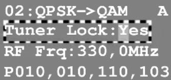
Select line 2 as described in 3.10.2.2.
If the flashing cursor is located in the second line the following sub-items can be called up by repeatedly pressing the Menu button:
| 1. Tuner Lock:Yes = Input signal | |
| 2. Sat Frq:11954MHz = | Satellite downlink frequency |
| 3. Sat SR:27500Kb = Symbol-rate | |
| 4. LNB Frq:10600MHz = | LNB local oscillator frequency (LO) |
| 5. LNB Set:18V/22kHz = | Multi-switch control |
| 6. CI:No Module = CAM type | |
| 7. CI:program = CAM program selection | |
| 8. Output:program = Output program selection | |
1. Tuner Lock: Yes
Input signal
No selection option, just a display showing whether the satellite tuner is synchronised with the input signal.
| Yes | = Tuner is synchronised. |
| No | = Tuner is not synchronised. |
2. Sat Frq:11954MHz
Satellite downlink frequency
The frequency input is entered in MHz using the numeric buttons. The data is transferred when the OK button is pressed.

| 3. Sat SR:27500Kb | Symbol-rateThe symbol rate is entered in kbaud using the numeric buttons.The data is transferred when the OK button is pressed. | |
| 4. LNB Frq:10600MHz | LNB local oscillator frequency (LO)The LO frequency is entered in MHz using the numeric buttons and depends on the satellite frequency range.→ Low band from 10.70-11.70 GHz ≦ LO = 9750 MHz→ High band from 11.70-12.75 GHz ≦ LO = 10600 MHzThe data is transferred when the OK button is pressed. | |
| 09750MHz | = LO frequency for low band | |
| 10600MHz | = LO frequency for high band | |
| 5. LNB Set:18V/22kHz | Controlling the integrated multi-switchPress the ▶ or ▶ cursor button to set the control voltage for the integrated multi-switch and hence select the SAT IF level. The data is transferred when the OK button is pressed after selection. | |
| 13V/ OK | = Vertical low band | |
| 18V/ OK | = Horizontal low-band | |
| 18V/22K | = Horizontal high-band | |
| 13V/22K | = Vertical high-band | |
| 6. CI:No Module | CAM typeDisplays the designation of an available CAM. If no CAM is available the message “No Module” appears. | |
| 7. CI:programm | CAM program selectionHere you can select which of the programs available in the reception signal are unlocked by the smart card. Only functions when a CAM is available. | |
| 8. Output:program | Output program selectionPress the OK button to access the selection menu.The display shows C1 F:ServicenamePress the ▶ or ▶ cursor button to display the service in the transport stream and press the OK button to select. The selected service is indicated by an asterisk C1*F:ServicenameWhen all the services have been selected, press EXIT and confirm with OK. All the selected services are now transferred to the output. | |
| 3.10.2.4 Display Line 3 | Select line 3 as described in 3.10.2.2 | |
| 02:QPSK→QAM A Tuner Lock:YesRF Frq:330,0MHzP010,010,110,103 | If the flashing cursor is located in the third line the following sub-items can be called up by repeatedly pressing the Menu button: | |
| 1. RF Frq:330,00MHz | = RF output frequency | |
| 2. RF Attn:00dB = RF T-pad attenuator | ||
| 3. QAM SR:6900KB = Output symbol rate | ||
| 4. QAM Mode:256 = Modulation process | ||
| 5. I/Q Inver:YES = Invert modulation spectrum | ||
| 6. Modulation:YES = Modulation On/Off | ||
| 7. QamSource:Tuner = Signal source for QAM modulator | ||
| 1. RF Frq:330,0MHz | RF output frequencyThe frequency output is entered in MHz using the numeric buttons. This is the channel centre frequency in QAM signals. The correct frequencies can be taken from the table in section 5.5.The data is transferred when the OK button is pressed. | |
| 2. RF Attn:00dB | RF T-pad attenuatorThe attenuation value for the output level is entered using the numeric buttons. A max. 9dB can be set.The data is transferred when the OK button is pressed.Watch the linearity of the wanted signal level for all the TWIN cards and adjust the output level by setting it to the RF T-pad attenuator, while watching the level parameters (see 5.6). | |
| 3. QAM SR:6900KB | Output symbol rateThe symbol rate is entered using the numeric keys. You can input between 2000 and 7200 kbaud.The data is transferred when the OK button is pressed.The symbol rate is in relation to the channel bandwidth (see 5.4).→ 7 MHz wide channel = 6000 kbaud symbol rate.→ 8 MHz wide channel = 6900 kbaud symbol rate. | |
| 4. QAM Mode:256 | Modulation processPress the ▶ or ▶ cursor button to set the modulation process to 16, 32, 64, 128 or 256 QAM. The data is transferred when the OK button is pressed. The modulation process depends on the gross data rate (see 5.4). | |
| 5. I/Q Inver:YES | Invert the modulation spectrumPress the ▶ or ▶ cursor buttons to invert the modulation spectrum.The data is transferred when the OK button is pressed. | |
| YES = pectrum inverted (inverted position)NO =pectrum not inverted (normal position) | ||
| 6. Modulation:YES | Modulation On/OffPress the ▶ or ▶ cursor buttons to switch the output signal on or off.The data is transferred when the OK button is pressed. | |
| YES = Modulation onNO = Modulation off | ||
| 7. QamSource:Tuner | Signal source for QAM modulatorYou have three possibilitys to select the source path for signal feed to QAM modulator (look block diagram 3.12.1). | |
| Tuner = Siganl from tuner → modulatorCI = Signal from CI → modulatorMux = Signal from TS-Rebuilder → modulatorTunerIt is a transparent 1:1 transmodulation of satellite transponder without any possibility of data manipulation.CIIt is a transparent 1:1 transmodulation of satellite transponder with encryption of TV programme without any possibility of data manipulation.Mux | ||
There occurs a conversion of the television programmes which was selected with the output program selection (line 3, item 7). With the TechniNet management software the comprehensive possibility of the data manipulation exists..
3.10.2.5 Display Line 4
Select line 4 as described in 3.10.2.2.
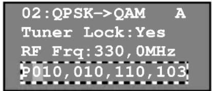
If the flashing cursor is located in the fourth line the following sub-items can be called up by repeatedly pressing the Menu button:
| 1. P010, 010, 110, 103 = | IP address |
| 2. M255, 255, 255, 000 = | Subnet mask |
| 3. G010, 010, 060, 001 = | Standard gateway |
| 4. T000, 010, 070, 066 = | SNMP trap destination IP |
| 5. MAC: 0006f41f4356 = | MAC address |
| 6. Temperature: 35°C = | Temperature |
| 7. MAINVer: 28DM000e = | Firmware version |
| 8. MCU Ver: 4, f8, 41 = | MCU software version |
| 9. FPGA Ver: 0, 0, 22 = | FPGA version |
| 10. Factory Setting? = | Factory default setting |
| 11. Reboot System? = | Reboot |
| 12. SN: 01009035002 = | Serial number |
| 1. P010, 010, 110, 103 | IP addressThe IP address is entered using the numeric keys. The data is automatically transferred after all 12 digits have been entered. The IP address is required for controlling the head station via a PC and should only be allocated to the network once! |
| 2. M255, 255, 255, 000 | Subnet maskThe subnet mask address is entered using the numeric keys. The data is automatically transferred after all 12 digits have been entered. |
| 3. G010, 010, 060, 001 | Standard gatewayThe standard gateway is entered using the numeric keys. The data is automatically transferred after all 12 digits have been entered. |
| 4. T000, 010, 070, 066 | SNMP trap destination IP addressThe trap destination IP address is entered using the numeric keys. The data is automatically transferred after all 12 digits have been entered. |
| 5. MAC: 0006f41f4356 | MAC addressDisplays the card's MAC address. No selection options. |
| 6. Temperature: 35°C | TemperatureDisplays the card temperature. No selection options. |
| 7. MAINVer: 28DM000e | Firmware versionDisplays the card's firmware version. No selection options. |
| 8. MCU Ver: 4, f4, 41 | MCU software versionDisplays the card's MCU software version. No selection options. |
| 9. FPGA Ver: 0, 0, 2210. Factory Setting? | FPGA-VersionDisplays the card's FPGA software version. No selection options.Factory default settingPress the OK button to get the selection option:OK=Y | EXIT=NConfirm by pressing OK and the entire card (receiving unit A and B) is reset to the factory default settings (Preset). All settings previously made are deleted irretrievably.Exit this option by pressing EXIT. The card only becomes operable again after the boot process is completed. |
| 11. Reboot System? | RebootPress the OK button to get the selection option:OK=Y | EXIT=NConfirm with OK to reboot the card - exit this option by pressing EXIT. The card only becomes operable again after the boot process is completed. |
| 12. SN:01009035002 | Serial numberDisplays the card's serial number. No selection options. |
3.10.3 Network Information Table (NIT)
The NIT describes the actual physical structure of the network. SkyCable cards are being able to generate a valid NIT. The programming of NIT is performed exclusively with the TechniNet Management Software.
3.10.3.1 Terrestrial Delivery System Descriptor
The NIT contains the Terrestrial Delivery Descriptor for the transmission of physical parameters of each transport multiplex. It helps the end devices in the automatic library lookup.
3.10.3.2 Logical Channel Numbering (LCN)
The NIT contains the Logical Channel Descriptor which provides a default channel number label for services. The intention of the Logical Channel Numbering is to provide an operator of cable network assigned virtual channel number, for each of the services available to the STB receiver.
3.11 SkyCable DVB-S2/DVB-T CI TWIN card (0000/5964)
3.11.1 Brief description
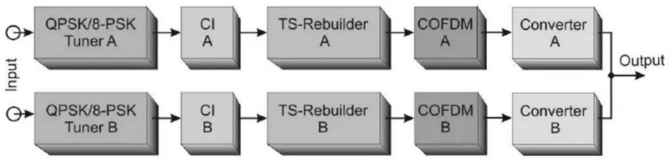
The DVB-S2/DVB-T CI TWIN card is used to demodulate two DVB-S2 satellite signals, enabling them to then be processed into two COFDM signals for the 100 MHz to 860 MHz frequency range. The use of a CI module with a suitable Smartcard also allows the channels to be decoded directly on the card.
flowchart
graph LR
    Input1["Input"] --> QPSK8PSK_TunerA["QPSK/8-PSK Tuner A"]
    Input2["Input"] --> QPSK8PSK_TunerB["QPSK/8-PSK Tuner B"]
    QPSK8PSK_TunerA --> CI_A["CI A"]
    CI_A --> TS_ReBuilderA["TS-Rebuilder A"]
    TS_ReBuilderA --> COFDMA["COFDM A"]
    COFDMA --> ConverterA["Converter A"]
    ConverterA --> Output
    QPSK8PSK_TunerB --> CI_B["CI B"]
    CI_B --> TS_ReBuilderB["TS-Rebuilder B"]
    TS_ReBuilderB --> COFDMB["COFDM B"]
    COFDMB --> ConverterB["Converter B"]
    ConverterB --> Output
Image: SkyCable DVB-S2/DVB-T CI TWIN card functional diagram
This card can only be operated in the TechniNet BS4 base unit as it does not have its own power supply or control panel and cannot supply voltage to an LNB. Operating and controlling the card is only possible via the programmable remote control or a special PC software application.
natural_image
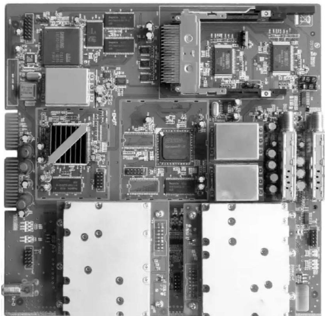
Top-down view of a computer motherboard with integrated circuits and connectors (no visible text or symbols)Image: SkyCable DVB-S2/DVB-T CI TWIN card (0000/5964)
3.11.2 Programming the SkyCable DVB-S2/DVB-T CI TWIN card
The following description explains how to program a SkyCable DVB-S2/DVB-T TWIN card using the programming remote control.
The programmer is connected to the 'Handset' port on the base unit via the supplied cable. The following message appears in the programmer display:
3.11.2.1 Display Start
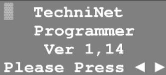
After pressing the cursor button ▶ the settings for card slot 01 are displayed; those for card slot 08 are displayed by pressing ◀. The other slots can be selected by pressing the cursor buttons again. The numbering of the slots goes upwards from left to right.
3.11.2.2 Display Line 1
03:QPSK->COFDM A Tuner Lock:Yes RF Frq:506,0MHz P010,010,110,105
Select the card slot as described in 3.11.2.1
The flashing cursor indicates the selected card slot (O2) and type (QPSK->COFDM). Press the Menu button to toggle between the two receiving units A and B.
03:QPSK->COFDM A Tuner Lock:Yes RF Frq:506,0MHz P010,010,110,105
Pressing the ▼ or ▲ cursor button moves the flashing cursor to another line. In this line you can call up additional menu items by pressing the Menu button.
3.11.2.3 Display Line 2
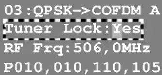
Select line 2 as described in 3.11.2.2.
If the flashing cursor is located in the second line the following sub-items can be called up by repeatedly pressing the Menu button:
| 1. Tuner Lock:Yes = Input signal | |
| 2. Sat Frq:11954MHz = Satellite downlink frequency | |
| 3. Sat SR:27500Kb = Symbol-rate | |
| 4. LNB Frq:10600MHz = LNB local oscillator frequency [LO] | |
| 5. LNB Set:18V/22kHz = Multi-switch control | |
| 6. CI:No Module = CAM type | |
| 7. CI:program = CAM program selection | |
| 8. Output:program = Output program selection | |
| 9. Dynamic Pmt:OFF = Dynamic PMT support |
1. Tuner Lock: Yes
Input signal No selection option, just a display showing whether the satellite tuner is synchronised with the input signal.
| Yes | = | Tuner is synchronised. |
| No | = | Tuner is not synchronised. |
2. Sat Frq:11954MHz
Satellite downlink frequency The frequency input is entered in MHz using the numeric buttons.
| The data is transferred when the OK button is pressed. | ||
| 3. Sat SR:27500Kb | Symbol-rateThe symbol rate is entered in kbaud using the numeric buttons.The data is transferred when the OK button is pressed. | |
| 4. LNB Frq:10600MHz | LNB local oscillator frequency (LO)The LO frequency is entered in MHz using the numeric buttons and depends on the satellite frequency range.→ Low band from 10.70-11.70 GHz ≦ LO = 9750 MHz→ High band from 11.70-12.75 GHz ≦ LO = 10600 MHzThe data is transferred when the OK button is pressed. | |
| 09750MHz | = LO frequency for low band | |
| 10600MHz | = LO frequency for high band | |
| 5. LNB Set:18V/22kHz | Controlling the integrated multi-switchPress the ▶ or ▶ cursor button to set the control voltage for the integrated multi-switch and hence select the SAT IF level. The data is transferred when the OK button is pressed after selection. | |
| 13V/ OK | = Vertical low band | |
| 18V/ OK | = Horizontal low-band | |
| 18V/22K | = Horizontal high-band | |
| 13V/22K | = Vertical high-band | |
| 6. CI:No Module | CAM typeDisplays the designation of an available CAM. If no CAM is available the message “No Module” appears. | |
| 7. CI:programm | CAM program selectionHere you can select which of the programs available in the reception signal are unlocked by the smart card. Only functions when a CAM is available. | |
| 8. Output:program | Output program selectionPress the OK button to access the selection menu.The display shows C1 F:ServicenamePress the ▶ or ▶ cursor button to display the service in the transport stream and press the OK button to select. The selected service is indicated by an asterisk C1*F:ServicenameWhen all the services have been selected, press EXIT and confirm with OK. All the selected services are now transferred to the output. | |
| 9. Dynamic Pmt:OFF | Dynamic PMT supportPress the ▶ or ▶ cursor button to set dynamic PMT support on or off. The data is transferred when the OK button is pressed. | |
| OFF | = Dynamic PMT support is switched off | |
| ON | = Dynamic PMT support is switched on | |
3.11.2.4 Display Line 3
Select line 3 as described in 3.11.2.2
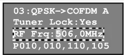
If the flashing cursor is located in the third line the following sub-items can be called up by repeatedly pressing the Menu button:
| 1. RF Frq:506,0MHz = | RF output frequency |
| 2. RF Attn:00dB = RFT-pad attenuator | |
| 3. COFDM Mode:64QAM = | Carrier modulation |
| 4. BandWidths:8M = Channel bandwidth | |
| 5. FEC:7/8 = Forward error correction | |
| 7. GuardInter:1/32 = | Guardintervall |
| 7. Modulation:YES = | Modulation On/Off |
| 8. SPEC:Invert = Invert modulation spectrum | |
| 1. RF Frq:506, 0MHz | RF output frequencyThe frequency output is entered in MHz using the numeric buttons. This is the channel centre frequency in COFDM signals. The correct frequencies can be taken from the table in section 5.5.The data is transferred when the OK button is pressed. | |
| 2. RF Attn:00dB | RF T-pad attenuatorThe attenuation value for the output level is entered using the numeric buttons. A max. 9dB can be set.The data is transferred when the OK button is pressed.Watch the linearity of the wanted signal level for all the TWIN cards and adjust the output level by setting it to the RF T-pad attenuator, while watching the level parameters (see 5.6). | |
| 3. COFDM Mode:64QAM | Sub-carrier modulation schemePress the ▶ or ▶ cursor button to set the sub-carrier modulation scheme.The data is transferred when the OK button is pressed. | |
| QPSK | = 2 Bits/symbol, maximum data rate 10,56 MBits/s | |
| 16QAM | = 4 Bits/symbol, maximum data rate 21,11 MBits/s | |
| 64QAM | = 6 Bits/symbol, maximum data rate 31,67 MBits/s | |
| 4. Bandwidths:8M | Channel spacingPress the ▶ or ▶ cursor button to set the channel spacing of 6, 7 or 8 MHz. The data is transferred when the OK button is pressed. | |
| 5. FEC:7/8 | Convolution coding (FEC)Press the ▶ or ▶ cursor button to set the forward error correction. The data is transferred when the OK button is pressed. | |
| 1/2 | = Highest | |
| 2/3 | = Normal | |
| 3/4 | = Adequate | |
| 5/6 | = Low | |
| 7/8 | = Very low | |
| 6. GuardInter:1/32 | Guard intervalPress the ▶ or ▶ cursor button to set the guard interval. The data is transferred when the OK button is pressed. | |
| 1/4 | = Long 1/16 = $short | |
| 1/8 = Medium 1/32 = Very short | |||
| 7. Modulation: YES | Modulation On/OffPress the ▶ or ▶ cursor buttons to switch the output signal on or off.The data is transferred when the OK button is pressed. | ||
| YES = Modulation on | |||
| NO = Modulation off | |||
| 8. SPEC: Invert | Invert the modulation spectrumPress the ▶ or ▶ cursor buttons to invert the modulation spectrum.The data is transferred when the OK button is pressed. | ||
| Invert = Spectrum inverted (inverted position) | |||
| Normal = Spectrum not inverted (normal position) | |||
| 3.11.2.5 Display Line 4 | Select line 4 as described in 3.11.2.2. | ||
| 03: QPSK->COFDM A Tuner Lock: Yes RF Frq: 506, 0MHz P010, 010, 110, 105 | If the flashing cursor is located in the fourth line the following sub-items can be called up by repeatedly pressing the Menu button: | ||
| 1. P010, 010, 110, 105 = IP address | |||
| 2. M255, 255, 255, 000 = Subnet mask | |||
| 3. G010, 010, 060, 001 = Standard gateway | |||
| 4. T000, 010, 070, 066 = SNMP trap destination IP | |||
| 5. MAC: 0006f41f4356 = MAC address | |||
| 6. Temperature: 35°C = Temperature | |||
| 7. MAINVer: 28DM2009 = Firmware version | |||
| 8. MCU Ver: 4, 18, 41 = MCU software version | |||
| 9. FPGA Ver: 0, 0, 22 = FPGA version | |||
| 10. Factory Setting? = Factory default setting | |||
| 11. Reboot System? = Reboot | |||
| 12. SN: 01009035002 = Serial number | |||
| 1. P010, 010, 110, 105 | IP addressThe IP address is entered using the numeric keys. The data is automatically transferred after all 12 digits have been entered. The IP address is required for controlling the head station via a PC and should only be allocated to the network once! | ||
| 2. M255, 255, 255, 000 | Subnet maskThe subnet mask address is entered using the numeric keys. The data is automatically transferred after all 12 digits have been entered. | ||
| 3. G010, 010, 060, 001 | Standard gatewayThe standard gateway is entered using the numeric keys. The data is automatically transferred after all 12 digits have been entered. | ||
| 4. T000, 010, 070, 066 | SNMP trap destination IP addressThe trap destination IP address is entered using the numeric keys. The data is automatically transferred after all 12 digits have been entered. | ||
| 5. MAC: 0006f41f4356 | MAC addressDisplays the card's MAC address. No selection options. | ||
| 6. Temperature:35°C | TemperatureDisplays the card temperature. No selection options. | ||
| 7. MAINVer:28DM2009 | Firmware versionDisplays the card's firmware version. No selection options. | ||
| 8. MCU Ver:4,18,41 | MCU software versionDisplays the card's MCU software version. No selection options. | ||
| 9. FPGA Ver:0,0,22 | FPGA-VersionDisplays the card's FPGA software version. No selection options. | ||
| 10. Factory Setting? | Factory default settingPress the OK button to get the selection option:OK=Y | EXIT=NConfirm by pressing OK and the entire card (receiving unit A and B) is reset to the factory default settings (Preset). All settings previously made are deleted irretrievably.Exit this option by pressing EXIT. The card only becomes operable again after the boot process is completed. | ||
| 11. Reboot System? | RebootPress the OK button to get the selection option:OK=Y | EXIT=NConfirm with OK to reboot the card - exit this option by pressing EXIT. The card only becomes operable again after the boot process is completed. | ||
| 12. SN:01009035002 | Serial numberDisplays the card's serial number. No selection options. | ||
3.11.3 Network Information Table (NIT)
The NIT describes the actual physical structure of the network. SkyCable cards are being able to generate a valid NIT. The programming of NIT is performed exclusively with the TechniNet Management Software.
3.11.3.1 Terrestrial Delivery System Descriptor
The NIT contains the Terrestrial Delivery Descriptor for the transmission of physical parameters of each transport multiplex. It helps the end devices in the automatic library lookup.
3.11.3.2 Logical Channel Numbering (LCN)
The NIT contains the Logical Channel Descriptor which provides a default channel number label for services. The intention of the Logical Channel Numbering is to provide an operator of cable network assigned virtual channel number, for each of the services available to the STB receiver.
4 Technical data
4.1 Base unit (0000/5960)
EN
| SAT IF input / Multi-switch | |
| Frequency range 950-2150 MHz | |
| Input / Output F jack | |
| Impedance 75 ohm | |
| Input level 50-90 dBμV (sum level) | |
| LNB supply 13/18 V – 22 kHz | |
| LNB stream Max 300 mA per input | |
| RF output | |
| Frequency range 42-862 MHz | |
| Input / Output F socket | |
| Impedance 75 ohm | |
| Operational output 107 dBμV maximum | |
| Measurement output -20 dB | |
| Cascade input -10 dB | |
| Configuration, Monitoring | |
| Network connection 2 x RJ45, Ethernet, 100BaseT, TCP/IP, SNMP | |
| Service connection RJ25, serial, for TechniNet programmers | |
| General | |
| Power supply | 190-250 VAC / 50-60 Hz |
| Power consumption Max. 250 W | |
| Nominal temperature range | 0-45°C |
| Relative humidity | 0-80 % |
| EMV | EN 50083-2, EN55022:2006+A1:2007, EN55024:1998+A1:2001+A2:2003 EN61000-3-2:2006, EN61000-3-3:2008 |
| Security | VDE 0855-1, DIN EN 60728-11:2005 |
| Dimensions (H x W x D) | 40 cm x 49.5 cm x 35.5 cm |
| Weight | 22.4kg |
4.2 SkyCable 8PSK/PAL CI TWIN card (0000/5962)
| Tuner | |
| Frequency range 950-2150 MHz | |
| Input level 45-85 dBμV | |
| DBS tuner input F jack | |
| Input impedance 75 ohm | |
| DVB-S demodulator EN 300 421 | |
| Demodulation QPSK | |
| Symbol rates 2-45 MBaud | |
| Roll off factor 0.20; 0.35 | |
| FEC Code rate 1/2, 2/4, 3/4, 5/6, 6/7, 7/8 (automatic) | |
| Interleaving Convolutional; I=12 | |
| Outer coding Reed Solomon 204, 188, T=8 | |
| DVB-S2 demodulator EN 302 307 | |
| Demodulation 8PSK, QPSK | |
| Symbol rates 2-45 MBaud | |
| Roll off factor 0.20; 0.25; 0.35 | |
| FEC block size 64 kbits | |
| FEC Code rate (LDPC) | 1/4, 1/3, 2/5, 1/2, 3/5, 2/3, 3/4, 4/5, 5/6, 8/9, 9/10 |
| Outer coding (BCH) | GF(216), t=8, 10, 12 |
| CI | |
| PCMCIA module | 2x PCMCIA module slot |
| Decoder | |
| Video decoder | MPEG-2, MP@ML |
| Audio decoder | MPEG-1, MPEG-2 |
| RF modulator | |
| Modulation | CCIR PAL B/G |
| S/N | ≥ 58 dB, weighted, at 16 MHz video hub ss |
| RF output converter | |
| Output frequency | 100...860MHz |
| C/N | ≥ 55 dB typically |
| Output level | 81-90 dBμV (+ 17 dB from collection area) |
| Harmonic product | ≤ -50 dB typically |
| Noise f0 > 10MHz f0 < 10MHz | ≤ 45 dBμV typically |
| General | |
| Power supply 3.3V / 5V / 12V DC | |
| Power consumption | 22 W |
| Nominal temperature range | 0-45°C |
| Relative humidity | 0-80 % |
| Dimensions (H x W x D) | (237 x 35 x 240) mm |
| Weight | 840g |
4.3 SkyCable DVB-S2/QAM CI TWIN card (0000/5963)
EN
| Tuner | |
| Frequency range 950-2150 MHz | |
| Input level 45-85 dBμV | |
| DBS tuner input F jack | |
| Input impedance 75 ohm | |
| DVB-S demodulator EN 300 421 | |
| Demodulation QPSK | |
| Symbol rates 2-45 MBaud | |
| Roll off factor 0.20; 0.35 | |
| FEC Code rate 1/2, 2/4, 3/4, 5/6, 6/7, 7/8 (automatic) | |
| Interleaving Convolutional; I=12 | |
| Outer coding Reed Solomon 204, 188, T=8 | |
| DVB-S2 Demodulator EN 302 307 | |
| Demodulation 8PSK, QPSK | |
| Symbol rates 2-45 MBaud | |
| Roll off factor 0.20; 0.25; 0.35 | |
| FEC block size 64 kbits | |
| FEC Code rate (LDPC) | 1/4, 1/3, 2/5, 1/2, 3/5, 2/3, 3/4, 4/5, 5/6, 8/9, 9/10 |
| Outer coding (BCH) | GF(216), t=8, 10, 12 |
| CI | |
| PCMCIA module | 2x PCMCIA module slot |
| DVB-C modulator | EN 300 429 |
| Modulation | 16/32/64/128/256 QAM |
| Channel bandwidth | 8 MHz (j.83/A) |
| Symbol rates 2-7.2 MBaud | |
| Nyquist roll-off | 0.15 |
| FEC coding | 204, 188 |
| MER | ≥ 40dB |
| RF output converter | |
| Output frequency | 100...860MHz |
| Output level | 81-90 dBμV (+ 17 dB from collection area) |
| Harmonic product | ≤ -50 dB typically |
| Noise f0 > 10MHz f0 < 10MHz | ≤ 45 dBμV typically |
| General | |
| Power supply 3.3V / 5V / 12V DC | |
| Power consumption | 22 W |
| Nominal temperature range | 0-45°C |
| Relative humidity | 0-80 % |
| Dimensions (H x W x D) | (237 x 35 x 240) mm |
| Weight | 810g |
4.4 SkyCable DVB-S2/DVB-T CI TWIN card (0000/5964)
| Tuner | |
| Frequency range 950...2.150 MHz | |
| Input level 45...85 dBμV | |
| DBS tuner input F jack | |
| Input impedance 75 ohm | |
| DVB-S demodulator EN 300 421 | |
| Demodulation QPSK | |
| Symbol rate 2...45 MBaud | |
| Roll off factor 0,20; 0,35 | |
| FEC Code rate 1/2 , 2/4, 3/4, 5/6, 6/7, 7/8 (automatic) | |
| Interleaving Convolutional; I=12 | |
| Outer coding Reed Solomon 204, 188, T=8 | |
| DVB-S2 demodulator EN 302 307 | |
| Demodulation 8PSK, QPSK | |
| Symbol rate 2...45 MBaud | |
| Roll off factor 0,20; 0,25; 0,35 | |
| FEC Block Size | 64 kbits |
| FEC Code rate (LDPC) | 1/4, 1/3, 2/5, 1/2, 3/5, 2/3, 3/4, 4/5, 5/6, 8/9, 9/10 |
| Outer coding (BCH) | GF(216), t=8, 10, 12 |
| CI | |
| PCMCIA module | 2x PCMCIA module slot |
| COFDM modulator | EN 300 744 |
| FFT mode | 2k |
| Modulation | QPSK, 16- und 64-QAM |
| Channel bandwidth | 6, 7, 8 MHz |
| FEC Code rate 1/2, 2/3, 3/4, 5/6, 7/8 | |
| Guard interval Δ/Tu | 1/4, 1/8, 1/16, 1/32 |
| MER | ≥ 36 dB (64-QAM, Equalizer) |
| RF output converter | |
| Output frequency | 100...860 MHz, adjacent channel qualified |
| Output level 81...90 dBμV (+ 17 dB from collection area) | |
| Harmonic product | ≤ -50 dB typical |
| Noise f0>10MHz f0<10MHz | ≤ 25 dBμV typical |
| General | |
| Power supply 3,3V / 5V / 12V DC | |
| Power consumption | 22 W |
| Nominal temperature range | 0...45°C |
| Relative humidity | 0...80 % |
| Dimension (H x W x D) | (237 x 35 x 240) mm |
| Weight | 810 g |
5 Helpful information
5.1 DVB-S data rate

| Modulation | Symbol rate (kSym/s) | Net data rate (MBit/s) | ||||
| FEC 1/2 | FEC 2/3 | FEC 3/4 | FEC 5/6 | FEC 7/8 | ||
| QPSK | 22000 20,274 | 27,033 30 | 0,411 33,790 | 35,479 | ||
| 27500 25,342 | 33,790 38 | 0,015 42,238 | 44,350 | |||
5.2 DVB-S2 data rates
| Modulation Pilot | Symbol rate (kSym/s) | Net data rate (MBit/s) | ||||||||
| FEC 1/2 | FEC 3/5 | FEC 2/3 | FEC 3/4 | FEC 4/5 | FEC 5/6 | FEC 8/9 | FEC 9/10 | |||
| QPSK | Off 22 | 2000 21,754 26 | 143 29,089 | 32,723 | 34,917 36 | 402 38,862 | 39,348 | |||
| Off 27 | 500 27,193 32 | 677 36,362 | 40,905 | 43,648 45 | 503 48,576 | 49,186 | ||||
| 8-PSK | Off 22 | 000 - 39,159 | 43,573 49 | 018 - 54 | 527 58,212 | 58,942 | ||||
| Off 27 | 500 - 48,950 | 466 61 | 273 - 68 | 159 72,756 | 73,677 | |||||
5.3 DVB-T data rates
| Modulation | FEC | Net data rate (MBit/s) | |||||||
| 7 MHz channel bandwidth Symbol rate: 5906 kSym/s | 8 MHz channel bandwidth Symbol rate: 6750 kSym/s | ||||||||
| /T_u=1/4 | /T_u=1/8 | /T_u=1/16 | /T_u=1/32 | /T_u=1/4 | /T_u=1/8 | /T_u=1/16 | /T_u=1/32 | ||
| QPSK2 Bits/s Hz | 1/2 | 4,354 | 4,838 | 5,123 | 5,278 | 4,98 | 5,53 | 5,58 | 6,06 |
| 2/3 | 5,806 | 6,451 | 6,830 | 7,037 | 6,64 | 7,73 | 7,81 | 8,04 | |
| 3/4 | 6,532 | 7,257 | 7,684 | 7,917 | 7,46 | 8,29 | 8,78 | 9,05 | |
| 5/6 | 7,257 | 8,064 | 8,538 | 8,797 | 8,29 | 9,22 | 9,76 | 10,05 | |
| 7/8 | 7,620 | 8,467 | 8,965 | 9,237 | 8,71 | 9,68 | 10,25 | 10,56 | |
| 16-QAM4 Bits/s Hz | 1/2 | 8,709 | 9,676 | 10,246 | 10,556 | 9,95 | 11,06 | 11,71 | 12,06 |
| 2/3 | 11,612 | 12,902 | 13,661 | 14,075 | 13,27 | 14,75 | 15,61 | 16,09 | |
| 3/4 | 13,063 | 14,515 | 15,369 | 15,834 | 14,93 | 16,59 | 17,56 | 18,10 | |
| 5/6 | 14,515 | 16,127 | 17,076 | 17,594 | 16,59 | 18,43 | 19,52 | 20,11 | |
| 7/8 | 15,240 | 16,934 | 17,930 | 18,473 | 17,42 | 19,35 | 20,49 | 21,11 | |
| 64-QAM6 Bits/s Hz | 1/2 | 13,063 | 14,515 | 15,369 | 15,834 | 14,93 | 16,59 | 17,56 | 18,10 |
| 2/3 | 17,418 | 19,353 | 20,491 | 21,112 | 19,91 | 22,12 | 23,42 | 24,13 | |
| 3/4 | 19,595 | 21,772 | 23,053 | 23,751 | 22,39 | 24,88 | 26,35 | 27,14 | |
| 5/6 | 21,772 | 24,191 | 25,614 | 26,390 | 24,88 | 27,65 | 29,27 | 30,16 | |
| 7/8 | 22,861 | 25,401 | 26,895 | 27,710 | 26,13 | 29,03 | 30,74 | 31,67 | |
5.4 DVB-C data rates
| Modulation 16 QAM | 32 QAM | 64 QAM | 128 QAM | 256 QAM | |
| Theoretical max. bandwidth usage in Bits/s Hz | 4 5 6 | 7 8 | |||
| Gross data rate in (MBit/s) at: Symbol rate 6.90 MBaud Channel bandwidth | 27.6 34 | 5 41.4 48 | 3 55.2 | ||
| Net data rate in (MBit/s) | 25.44 3 | 1.97 38 | 15 44.15 | 50.87 |
To ascertain the net data rate, the following criteria need to be taken into consideration:
■ Channel bandwidth B = (7 MHz or 8MHz)
■ Modulation process (64 QAM or 256 QAM)
■ Roll-off factor r = 0.15
■ Frame length in 204 byte transport stream
■ RS code (204,188)
■ 6 bit per Symbol [with 64 QAM]
8 bit per Symbol [with 256 QAM]
■ The code conversion for 8-bit [= 1 byte] wide words to 6-bit wide symbols means changing the frame length from 204 bytes to 272 symbols in the data stream.
Example:
With reference to an 8 MHz channel and 64 QAM this gives:
$$ V _ {S y m b o l} = \frac {B}{1 + r} = \frac {8 M H z}{1 . 1 5} = 6, 9 6 \frac {M S y m b o l e}{s} $$
Therefore a maximum of 6.96 - 10^5 symbols per second can be transferred. As each symbol consists of 6 bits, this gives a gross bit rate of:
$$ \left(V _ {b i t}\right) _ {B r u t t o} = n \cdot \frac {b i t}{S y m b o l} \cdot V _ {S y m b o l} = 6 \frac {b i t}{S y m b o l} \cdot 6, 9 6 \cdot 1 0 ^ {6} \frac {\text { Symbole }}{s} $$
$$ (V _ {b i t}) _ {B r u t t o} = 4 1, 7 6 M b i t / s $$
To calculate the net bit rate the external error correction according to Reed Solomon coding needs to be considered as well.
$$ \left(V _ {b i t}\right) _ {\text { Netto }} = R _ {R S} \cdot \left(V _ {b i t}\right) _ {\text { Brutto }} = \frac {1 8 8}{2 0 4} \cdot 4 1, 7 6 M b i t / s $$
$$ (V _ {b i t}) _ {\text { Netto }} = 3 8, 5 \text { Mbit / s } $$
5.5 Channel / Frequency conversion table (BC grid)
| Band | Channel | Analogue BT Frequency (MHz) | Digital Centre Frequency (MHz) | Band | Channel | Analogue BT Frequency (MHz) | Digital Centre Frequency (MHz) | Band | Channel | Analogue BT Frequency (MHz) | Digital Centre Frequency (MHz) |
| I | 02 04 | 8.25 | 25 330 | S 21 3 | 03.25 306 | 35 583,25 586 | |||||
| 03 05 | 5.25 | S 22 3 | 11.25 314 | 36 591,25 594 | |||||||
| 04 06 | 2.25 | S 23 3 | 19.25 322 | 37 5 | 99,25 602 | ||||||
| Lower spezial channel area | S 02^1) | 112.25 113 | S 24 327 | 25 338 | 38 607 | 25 610 | V | ||||
| S 03^1) | 19.25 121 | S 25 335 | 39 615 | 25 618 | |||||||
| S 04^1) | 126.25 128,5 | S 26 34 | 3.25 34 | 40 62 | 3,25 626 | ||||||
| S 05^1) | 133.25 135,7 | S 27 35 | 1.25 35 | 41 63 | 1,25 634 | ||||||
| S 06 1 | 40.25 142 | S 28 359 | 2.55 362 | 42 639 | 25 642 | ||||||
| S 07 1 | 47.25 149 | S 29 367 | 7.25 370 | 43 647 | 25 650 | ||||||
| S 08 1 | 54.25 156 | S 30 375 | 2.55 378 | 44 655 | 25 658 | ||||||
| S 09 1 | 61.25 163 | S 31 383 | 3.25 386 | 45 663 | 25 666 | ||||||
| S 10 1 | 68.25 170 | S 32 391 | 1.25 394 | 46 671 | 25 674 | ||||||
| III | 05 17 | 5.25 177,5 | S 33 399 | 25 402 | 47 679 | 25 682 | |||||
| 06 18 | 2.25 184,5 | S 34 407 | 25 410 | 48 687 | 25 690 | ||||||
| 07 18 | 9.25 191,5 | S 35 415 | 25 418 | 49 695 | 25 698 | ||||||
| 08 19 | 6.25 198,5 | S 36 423 | 25 426 | 50 703 | 25 706 | ||||||
| 09 20 | 3.25 205,5 | S 37 431 | 25 434 | 51 711 | 25 714 | ||||||
| 10 21 | 10.25 212,5 | S 38 439 | 25 442 | 52 719 | 25 722 | ||||||
| 11 21 | 7.25 219,5 | S 39 447 | 25 450 | 53 727 | 25 730 | ||||||
| 12 22 | 4.25 226,5 | S 40 455 | 25 458 | 54 735 | 25 738 | ||||||
| Upper spezial channel area | S 11 2 | 31.25 233,5 | S 41 4 | 63.25 466 | 55 743,25 746 | ||||||
| S 12 2 | 38.25 240,5 | 21 | 471.25 47 | 74 56 7 | 51,25 754 | ||||||
| S 13 2 | 45.25 247,5 | 22 | 479.25 48 | 82 57 7 | 59,25 762 | ||||||
| S 14 2 | 52.25 254,5 | 23 | 487.25 49 | 90 58 7 | 67,25 770 | ||||||
| S 15 2 | 59.25 261,5 | 24 | 495.25 49 | 98 59 7 | 75,25 778 | ||||||
| S 16 2 | 66.25 268,5 | 25 | 503.25 50 | 06 60 7 | 83,25 786 | ||||||
| S 17 2 | 73.25 275,5 | 26 | 511.25 51 | 14 61 7 | 91,25 804 | ||||||
| S 18 2 | 80.25 282,5 | 27 | 519.25 52 | 22 62 7 | 99,25 792 | ||||||
| S 19 2 | 87.25 289,5 | 28 | 527.25 53 | 30 63 8 | 07,25 810 | ||||||
| S 20 2 | 94.25 296,5 | 29 | 535.25 538 | 64 8 | 15,25 818 | ||||||
| 30 | 543,25 546 65 823,25 826 | ||||||||||
| 31 | 551,25 554 66 831,25 834 | ||||||||||
| 32 | 559,25 562 67 839,25 842 | ||||||||||
| 33 | 567,25 570 68 847,25 850 | ||||||||||
| 34 | 575,25 578 | 69 8 | 55,25 858 | ||||||||
5.6 Level parameters for internal distribution networks
Useful signal level to any antenna socket in accordance with EN 60728-1
| Application Wanted signal level (dBμV) | ||
| Minimum Maximum | ||
| AM-TV 60 80 | ||
| FM-TV (Sat-IF) 47 77 | ||
| Radio - stereo 50 70 | ||
| Radio - mono 40 70 | ||
| DVB-C (64-QAM) 47 67 | ||
| DVB-C (256-QAM) 54 74 | ||
| DVB-T COFDM (16-QAM) | FEC dBμV | 74 |
| 1/2 32 | ||
| 2/3 36 | ||
| 3/4 39 | ||
| 5/6 42 | ||
| 7/8 45 | ||
| DVB-T COFDM (64-QAM) | FEC dBμV | 74 |
| 1/2 42 | ||
| 2/3 45 | ||
| 3/4 48 | ||
| 5/6 51 | ||
| 7/8 54 | ||
6 Accessoires
| Item number | Description |
| 0000/5960 | BS4 Professional base station |
| 0000/5961 | BS4 programming remote control |
| 0000/5962 | SkyCable 8PSK/PAL CI TWIN card |
| 0000/5963 | SkyCable DVB-S2/QAM CI TWIN card |
| 0000/5964 | SkyCable DVB-S2/DVB-T CI TWIN card |
| 0001/5608 | HAV 35 broadband amplifier |
| 0000/3145 | 20 dB adjustable attenuator |
| 0000/3434 | TechniTouch measuring device |
EN
7 Declaration of Conformity
EN
EC-Declaration of Conformity

marking
We, Manufacturer/Importer
(full address)
declare that the product
(description of the apparatus, system, installation to which it refers)
Kabelkopfstation
TechniNet BS 4
Brand: TechniSat
is in conformity with
Council Directive 2004/108/EC (EMC Directive)
Standarde to which conformity is declared:
EN50083-2 2008
Cable networks for television signals, sound signals and interactive services - Part 2: Electromagnetic compatibility for equipment
EN55022:2006+A1:2007
Information technology equipment - Radio disturbance characteristics - Limits and methods of measurement
EN55024:1998+A1:2001+A2:2003
Information technology equipment - Immunity characteristics - Limits and methods of measurement
EN61000-3-2:2006
Electromagnetic compatibility (EMC) - Part 3-2: Limits - Limits for harmonic current emissions (equipment input current up to and including 16A per phase)
EN61000-3-3:2008
Electromagnetic compatibility (EMC) - Part 3-3: Limits: Limitation of voltage changes, voltage fluctuations and flicker in public low-voltage supply systems, for equipment with rated current up to 164 per phase
▶ please note reverse side
TechniSat
Digital GmbH
TechniPark
D-54550 Daun/Vulkanelfel
(Stamp)
Manufacturer/Importer
Date:
25.10.2010
Signature:
Name:
Stephan Schaaf

TESTED IN GERMANY
Date: 15.09.2010
Ref.-No.: 10/09-0049
Based on Test-Report, Ref.-No. 10/09-0049
ACCREDITATIONS:
- ISO/IEC170252005
- KBA-P 00088-96
pkm elektronjc GmbH

EN
Your device is CE approved and meets all necessary EU standards.
Subject to changes and printing errors. Status 2/11
Reproduction and copies are only allowed with the consent of the publisher.
TechniSat is a registered trademark of
TechniSat Digital GmbH · P.O. Box 560 · 54541 Daun · Germany · www.technisat.com
TechniSat
www.technisat.de

- EC-Declaration of Conformity
- Content
- Safety instructions
- For your own protection you should read the safety notes carefully before using the device.
- In the following circumstances you should disconnect the device from the mains power and consult an expert:
- Danger and installation instructions of particular note:
- For your safety:
- Please observe all safety instructions at all times!
- Description
- TechniNet BS4 (0000/5960) base unit
- Implementation
- Wall mounting
- 19" rack mounting
- Earthing
- Connecting the power supply
- Connecting the SAT IF inputs and outputs
- Connecting the HF outputs
- Connecting the LAN
- Implementing the SkyCable TWIN cards
- Levelling the head station
- Installation example
- Programming remote control (0000/5961)
- SkyCable 8PSK/PAL CI TWIN card (0000/5962)
- Brief description
- Programming the SkyCable 8PSK/PAL CI TWIN card
- Display Start
- Display Line 1
- Display Line 2
- Tuner Lock: Yes
- Display Line 4
- SkyCable DVB-S2/QAM CI TWIN card (0000/5963)
- Brief description
- Programming the SkyCable DVB-S2/QAM CI TWIN card
- Display Start
- Display Line 1
- Display Line 2
- Sat Frq:11954MHz
- Display Line 4
- Network Information Table (NIT)
- Terrestrial Delivery System Descriptor
- Logical Channel Numbering (LCN)
- SkyCable DVB-S2/DVB-T CI TWIN card (0000/5964)
- Brief description
- Programming the SkyCable DVB-S2/DVB-T CI TWIN card
- Display Start
- Display Line 1
- Display Line 2
- Display Line 3
- Network Information Table (NIT)
- Terrestrial Delivery System Descriptor
- Logical Channel Numbering (LCN)
- Technical data
- Base unit (0000/5960)
- SkyCable 8PSK/PAL CI TWIN card (0000/5962)
- SkyCable DVB-S2/QAM CI TWIN card (0000/5963)
- SkyCable DVB-S2/DVB-T CI TWIN card (0000/5964)
- Helpful information
- DVB-S data rate
- DVB-S2 data rates
- DVB-T data rates
- DVB-C data rates
- Level parameters for internal distribution networks
- Declaration of Conformity
Brand : TECHNISAT
Model : TechniNet BS4
Category : Uncategorized