
Technipolar 2 S - Air-conditioner TECHNISAT - Free user manual and instructions
Find the device manual for free Technipolar 2 S TECHNISAT in PDF.


| Type | Portable air conditioner (monoblock) |
| Cooling capacity | 9000 BTU/h (2.6 kW) |
| Modes | Cooling, Fan, Dehumidifying, Timer, Auto, Night |
| Temperature range | 18°C – 32°C |
| Recommended room size | 13 m² – 25 m² |
| Dehumidification capacity | 26 L/day |
| Noise level | 53 – 65 dB |
| Refrigerant | R290 (propane), 205 g |
| Power consumption (cooling) | 1 kW/h (approx. 1 kWh) |
| EER (Energy Efficiency Ratio) | 2.6 |
| Energy efficiency class (cooling) | A |
| Power supply | 220 – 240 V ~ 50 Hz, 1200 W |
| Dimensions (W×H×D) | 44 × 69.5 × 32.5 cm |
| Weight | 27 kg |
| Exhaust hose length | 1.5 m (max.), diameter 15 cm |
| Protection class | IPX0 |
| Display | 7-segment, 2 digits |
| Controls | Control panel on unit + remote control |
| Filter type | Washable mesh filter (clean weekly) |
| Condensation drainage | Manual (lower drain) or continuous (upper drain with hose) |
| Wheels | Yes, for mobility |
| Special features | Timer (1-24 h), Night mode, Auto mode, fan speeds, temperature unit switch (°C/°F) |
| Safety features | R290 flammability warnings, ground fault protection, minimum room area 13 m² |
| Package contents | Air conditioner, remote control, exhaust hose, condensate hose, window seal kit, manual |
| Warranty | 24 months (legal warranty) |
Frequently Asked Questions - Technipolar 2 S TECHNISAT
User questions about Technipolar 2 S TECHNISAT
0 question about this device. Answer the ones you know or ask your own.
Ask a new question about this device
Download the instructions for your Air-conditioner in PDF format for free! Find your manual Technipolar 2 S - TECHNISAT and take your electronic device back in hand. On this page are published all the documents necessary for the use of your device. Technipolar 2 S by TECHNISAT.
USER MANUAL Technipolar 2 S TECHNISAT
natural_image
Line drawing of a portable air conditioner unit with control panel and side door (no text or symbols)TECHNIPOLAR 2 S
CONTENTS
DEUTSCH 3-27
ENGLISH 29-53
POLSKIE....55-79
Bedienungsanleitung
TECHNIPOLAR 2 S
natural_image
Line drawing of a portable air conditioner unit with control panel and side door (no text or symbols)2 Vorwort
natural_image
Diagram of a cylindrical object with internal parallel grooves and two directional arrows indicating orientation (no text or symbols)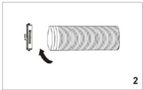
natural_image
Diagram showing a cylindrical object with a curved arrow indicating rotation or change, next to a small rectangular component (no text or symbols)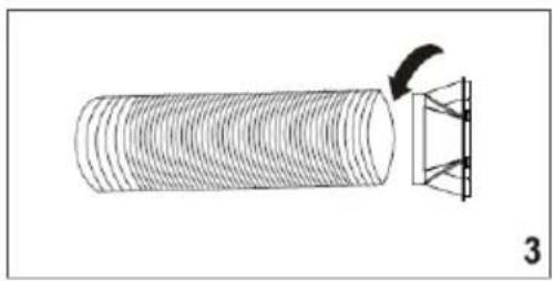
natural_image
Diagram showing a cylindrical object with a curved arrow pointing to a structural component, labeled '3' (no text or symbols on the diagram itself)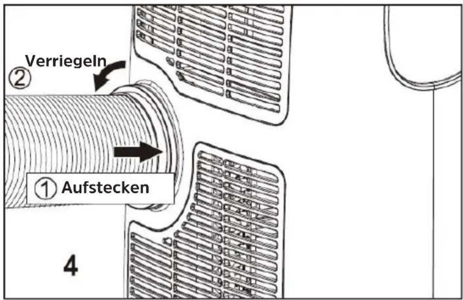
natural_image
Close-up of a hand cleaning a window frame with corrugated metal lining (no text or symbols visible)natural_image
Black-and-white photo of a hand reaching toward a window with blurred trees in the background (no text or symbols visible)natural_image
Close-up of a hand holding a small object near a window (no visible text or symbols)natural_image
Close-up of a hand holding a white plastic clip next to a wall-mounted device (no visible text or symbols)natural_image
Close-up of a window with visible door and window frame, no text or symbols presentnatural_image
Black and white photo of a window with a door, showing the exterior and side panels (no text or symbols visible)natural_image
Close-up of a hand holding a thin, thin object against a plain background (no text or symbols visible)natural_image
Close-up of a striped fabric or cloth hanging from a glass window (no visible text or symbols)natural_image
Diagram of a portable air conditioner unit connected to a coiled hose, with no visible text or symbols7 Bedienung
natural_image
Simple line drawing of a portable device with a handle and cable, no text or symbols present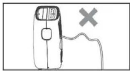
natural_image
Simple line drawing of a handheld device with a switch and a cross symbol, no text or labels present.7.5 Lüftermodus
natural_image
Simple line drawing of a hammer and sickle with an arrow indicating bidirectional movement (no text or symbols)natural_image
Simple line drawing of a portable air purifier with a handle and cable, no text or symbols present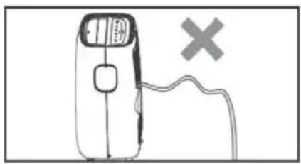
natural_image
Simple line drawing of a handheld device with a cross symbol on the right side (no text or labels)natural_image
Line drawing of a portable air conditioner unit with front panel and side panels, showing internal components and a black arrow indicating rotation (no text or symbols)Mobile air conditioning unit with fan and dehumidifier function.
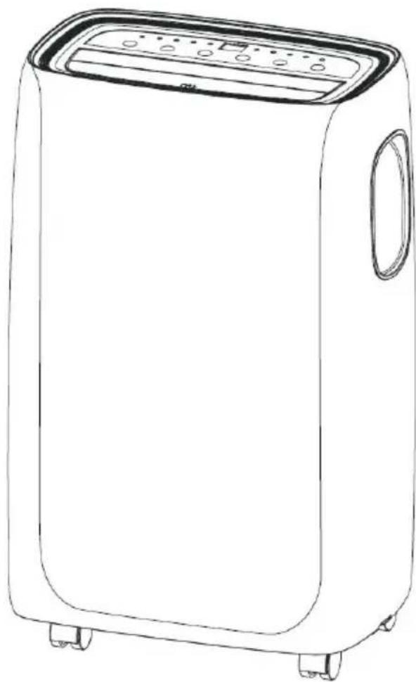
natural_image
Line drawing of a portable air conditioner unit with control panel and side door (no text or symbols)2 Preface
Dear Customers,
Thank you for choosing this air conditioner from TechniSat.
This instruction manual is intended to help you get to know the extensive functions that your new unit offers, and to make the best use of them. It will help you to use the product as intended and safely. It is intended for anyone installing, operating, cleaning or disposing of the unit.
Store the instruction manual in a safe place for later use.
You can find a current version of the instruction manual in the download area for your product on the TechniSat website www.technisat.de.
We hope you enjoy your TechniSat product!
Your TechniSat Team
3 Index
2 Preface....30
3 Index....31
4 Safety instructions....32
4.1 Signs and symbols used 32
4.2 Intended use....33
4.3 Safe use of air conditioners 33
4.4 Disposal instructions....35
5 Illustrations ....36
6 Installation instructions....37
6.1 Exhaust air discharge....37
6.2 Installing the window kit 38
6.3 Site of installation....39
7 Operation.... 40
7.1 Control panel....40
7.2 Switching on and off 40
7.3 Cooling mode 41
7.4 Dehumidifier mode 42
7.5 Fan mode....42
7.6 Automatic mode 43
8 Timer mode....43
8.1 Programming the timer....43
9 Using the remote control.... 44
9.1 Inserting the batteries 44
9.2 Overview....45
9.3 Activating special functions with the remote control....46
9.3.1 Ventilation outlet 46
9.3.2 Changing the temperature unit 46
9.3.3 Night mode....46
10 Servicing and maintenance....47
10.1 Draining the condensation....47
10.2 Cleaning the unit 48
10.3 Activities at the start / end of the season 49
11 Troubleshooting ....49
12 Technical data....51
13 Legal notices 52
13.1 Service instructions....52
14 Notes....53
4 Safety instructions
4.1 Signs and symbols used
In this instruction manual and on the unit:

Indicates a safety instruction which can lead to serious injuries or death if not observed. Note the following signal words:
DANGER - Severe injury with fatal consequences
WARNING - Severe injury, with possibly fatal consequences
CAUTION - Injury

Indicates a note that you must observe to avoid equipment defects, data loss/misuse or unintended operation. It also describes additional functions of your unit.

Beware of electrical voltage. Follow all safety instructions to avoid electric shock. Do not open the unit under any circumstances.

Danger from combustible substances. Follow all safety instructions. Carelessness in proximity to flammable substances can lead to fire.

Pay attention to all notices and safety information in the instruction manual.

Indoor use - units with this symbol are only suitable for indoor use.

Protection class II - Electrical appliances in protection class II are electrical appliances that have continuous double and/or reinforced insulation and no connection options for a protective conductor. The housing of an insulation-enclosed electrical appliance of protection class II may partially or completely form the additional or reinforced insulation.

Your unit bears the CE symbol and complies with all the requisite EU standards.

Electronic appliances do not belong in household waste, but must be disposed of properly - in accordance with Directive 2012/19/EU of the European Parliament and Council of 4 July 2012 on waste electrical and electronic equipment. Please return this unit to the designated public collection point for disposal at the end of its service life.
4.2 Intended use
The TechniSat TECHNIPOLAR 2 S air conditioner is for cooling, ventilating and heating living spaces measuring between 13 m ^2 and 25 m ^2 .
4.3 Safe use of air conditioners
Please observe the following instructions in order to minimise safety risks, to avoid damage to the unit and to contribute to environmental protection. Please read all safety instructions carefully and keep them for future reference. Always follow all the warnings and instructions in this instruction manual and on the back of the unit.

WARNING!
Flammable substances. The unit is filled with R290 propane gas. It is essential to observe the manufacturer's guidelines for repair and service work. Servicing must only be carried out by trained specialist personnel.

WARNING!
The unit must only be installed, operated and stored in rooms with a minimum area of 13 m^2 .

WARNING!
Do not open the unit under any circumstances. Touching live parts endangers life!

Observe all of the following instructions for the intended use of the unit and to prevent defects and personal injury.
The unit is not intended for use by persons (including children) with reduced physical, sensory or mental capabilities, or lack of experience and knowledge, unless they have been given supervision or instruction concerning use of the unit by a person responsible for their safety.
Children must be supervised to ensure that they do not play with the unit.
Do not use this unit for functions other than those described in this instruction manual.
If the power cord is worn or damaged, it must only be replaced by a qualified service technician using genuine spare parts.
The plug must be firmly and completely inserted into the socket. There is a risk of electric shock or fire.
Do not connect other appliances to the same socket, there is a risk of electric shock.
Neither the air conditioner nor the power cord must be dismantled or modified, otherwise there will be a risk of electric shock or fire. All other work on the unit must be carried out by a qualified technician.Do not place the mains cable or air conditioner near a radiator, heater or other heat source. There is a risk of electric shock or fire.
The unit is equipped with a cable with an earthed conductor connected to an earthing pin or lug. The plug must be plugged into a properly-installed and grounded electrical outlet. Under no circumstances should the earthing pin or tab be cut off or removed from the plug.
The unit must be used or stored in such a way that it is protected from moisture, such as condensed water, splashed water, and the like.
Transport your air conditioner in a vertical position and place it on a sturdy, flat surface while in use. If the unit is transported lying on its side, it should stand upright for 6 hours and only then be connected to the power supply.
Switch off the unit or the remote control using the switch on the control panel. Do not start or stop operation by plugging in or unplugging the power cord. There is a risk of causing electric shock.
Do not press the buttons on the control panel with wet or damp hands.
Do not use hazardous chemicals to clean the unit and keep them away from the unit. To avoid damaging the surface, only clean the air conditioner with a soft cloth. Do not use wax, thinners or strong cleaning agents. Do not use the unit in the presence of flammable substances or vapours, such as alcohol, insecticides, petrol, and the like.
If the air conditioner makes unusual noises or emits smoke or an unusual smell, pull the plug out of the socket immediately.
Do not clean the unit with water. Water can enter the unit and damage the insulation, creating the risk of electric shock. If water has entered the unit, immediately pull the power plug out and contact customer service.
The unit should be lifted and installed by at least two people.
Ensure that all accessories are removed from the packaging before use.
When removing and installing the filter, do not touch the metal parts of the air conditioner to avoid cuts. There is a risk of personal injury.
Do not block the air inlet or outlet vents on the air conditioner. A reduced air flow leads to poor performance and can damage the unit.
Always grip the plug when plugging in or unplugging the air conditioner. Never pull the plug out of the socket by pulling on the cable. Otherwise there is a risk of electric shock and damage.Place the air conditioner on a sturdy, level surface that can support a load up to 50 kg. Installation on a non-solid or uneven surface can lead to damage and personal injury.
For the most efficient operation, close all doors and windows in the room. Make sure that the exhaust hose is routed outside to ensure efficient operation.
IMPORTANT - EARTHING METHOD
This product is factory-fitted with a power cord that has a three-pin grounded plug. It must only be connected to an electrical outlet that is equipped in accordance with the National Electrical Code and applicable local codes and regulations for earthing. If the circuit does not have a grounded outlet, it is the responsibility and obligation of the customer to replace the existing outlet in accordance with the National Electrical Code and applicable local codes and regulations. The third earthing contact must never be cut off or removed. Never use the cable, plug or unit if any of them are damaged. Only use the unit with an extension cable
if it has been checked and tested by a qualified electrician. If
the earthed plug is incorrectly connected, there is a risk of fire, electric shock and / or injury to persons in connection with the unit. Contact a qualified service technician if you have any doubts as to whether the unit is properly earthed.
ELECTRICAL CONNECTIONS
Before plugging the unit into the wall socket, check the following:
That the mains voltage corresponds to the value specified on the type plate on the back of the unit.
That the socket and power circuit are suitable for the unit.
That the mains socket matches the plug. If this is not the case, have the plug replaced.
That the mains socket is adequately earthed. Failure to observe these important safety instructions releases the manufacturer from any liability.
4.4 Disposal instructions
Important information for proper disposal of the product according to EC Directive 2012/19/EU.
At the end of its service life, the product must not be disposed of as residential waste. It must be taken to a special municipal collection point or to a retailer who offers this service.
The separate disposal of household appliances avoids possible negative effects on the environment and the health of persons resulting from improper disposal. It also enables components to be reused, resulting in significant energy and resource savings. As a reminder of the need to dispose of household appliances separately the product is marked with a crossed out refuse container on wheels.
5 Illustrations
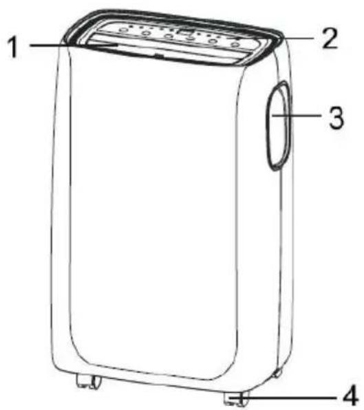
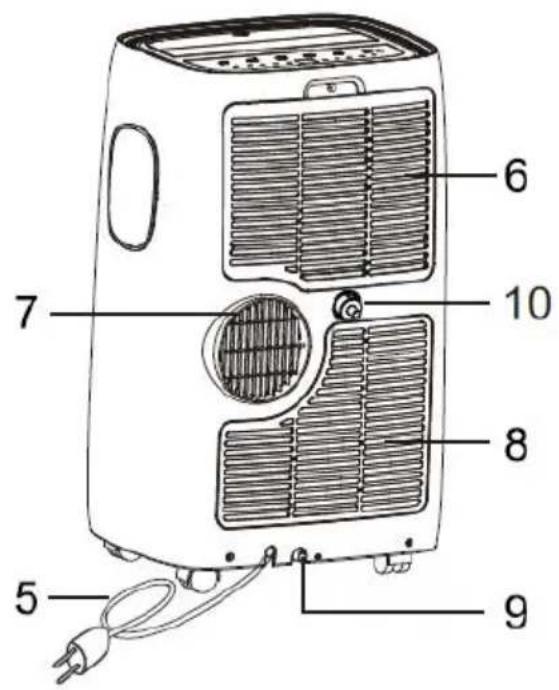
1 Fan opening
2 Operating panel
3 Grip recesses (both sides)
4 Wheels
5 Mains cable
6 Filter unit air inlet
7 Exhaust air connector
8 Air inlet
9 Lower condensation drain
10 Upper condensation drain
6 Installation instructions
6.1 Exhaust air discharge
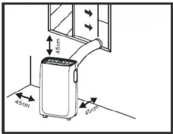
In cooling mode, the unit must be placed near a window or opening so that the warm exhaust air can be directed outside.
Place the unit on a level floor, ensure that there is a minimum distance of 45 cm around the unit, and that it is close to an earthed socket.
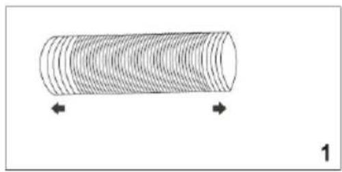
- Extend the hose to the desired length by unravelling it (Fig. 1)
- Screw it onto the hose inlet (Fig. 2).
- Screw the hose outlet onto the other end of the hose (Fig. 3).
- Mount the hose inlet onto the exhaust air connection (7) (Fig. 4).
- Attach the hose outlet to the window kit (see „6.2 Installing the window kit“).
natural_image
Diagram of a cylindrical object with internal parallel grooves, marked with arrows and number 1 (no text or symbols on the object itself)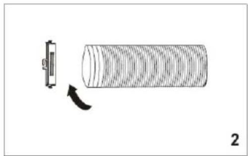
natural_image
Diagram showing a cylindrical object with a small rectangular component and an arrow indicating rotation (no text or symbols)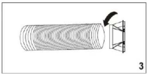
natural_image
Diagram showing a cylindrical object with a curved arrow pointing to a structural component, labeled '3' (no text or symbols on the diagram itself)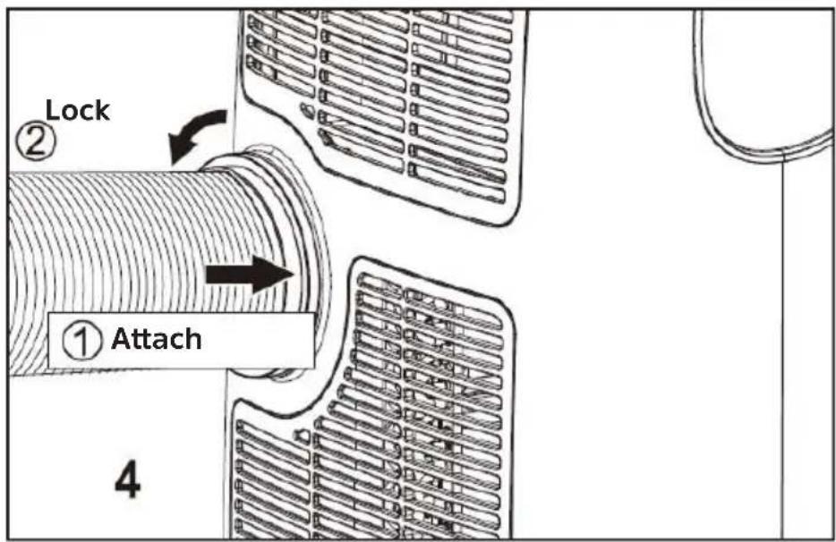
6.2 Installing the window kit
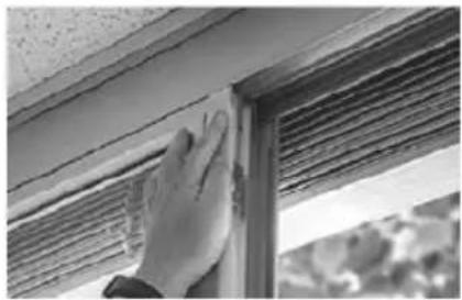
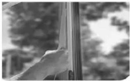
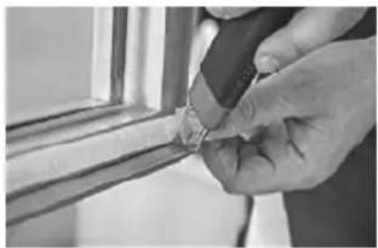
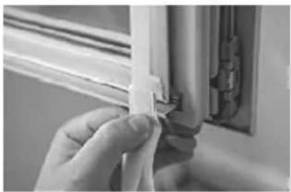
The window kit is designed to seal casement windows. To install proceed as follows:
Fig. 5
natural_image
Close-up of a hand cleaning or adjusting a wooden window frame (no text or symbols visible)Glue the Velcro tape to the window frame.
Fig. 6
natural_image
Black and white photo of a person's hand near a window with blurred trees in the background (no text or symbols visible)Glue the Velcro tape to the frame of the window.
Fig. 7
natural_image
Close-up of a hand holding a small object near a window frame (no visible text or symbols)Shorten the Velcro tape at the corners.
Fig. 8
natural_image
Close-up of a hand holding a white plastic clip next to a wooden frame (no text or symbols visible)Make sure that the corners are flush.
Fig. 9
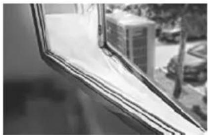
natural_image
Close-up of a window with visible door frame and window edges, no text or symbols presentAttach the window seal.
Fig. 10
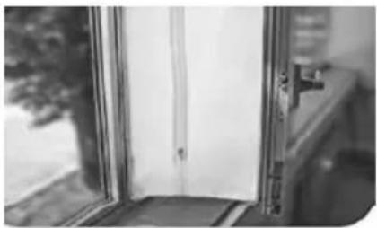
natural_image
Black-and-white photo of a window with a door and handle, no visible text or symbolsMake sure that both halves are aligned with each other.
Fig. 11
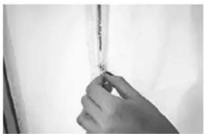
natural_image
Close-up of a hand holding a thin, thin object against a plain background (no text or symbols visible)Open the zipper at the side.
Fig. 12
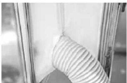
natural_image
Close-up of a striped fabric or material inside a transparent glass container (no text or symbols visible)Insert the exhaust hose into the opening and close the zipper.
6.3 Site of installation
The unit should be set up on a solid surface to minimise noise and vibration. To ensure a stable and secure state, place the unit on a smooth, level floor that is solid enough to support the weight of the unit.
The unit is equipped with wheels to make installation easier. However, it should only be wheeled on smooth, flat surfaces. Be careful when wheeling it on carpets. Be careful and protect the floors when you roll the unit over wooden floors. Do not try to roll the unit over objects.
The unit must be placed within reach of a properly rated earthed socket.
Never place any obstacles around the air inlet or outlet vents on the unit.
Leave a distance of at least 45 cm to the wall to achieve efficient air conditioning.
The hose can be extended, but should be kept as short as possible. Also make sure that the hose has no kinks and does not sag.
natural_image
Diagram of a device with a curved pipe and a horizontal line intersecting it, no text or symbols present.7 Operation
The control panel is located on the top of the unit.
However, you need to use the remote control in order to utilise the full potential of the unit.
7.1 Control panel
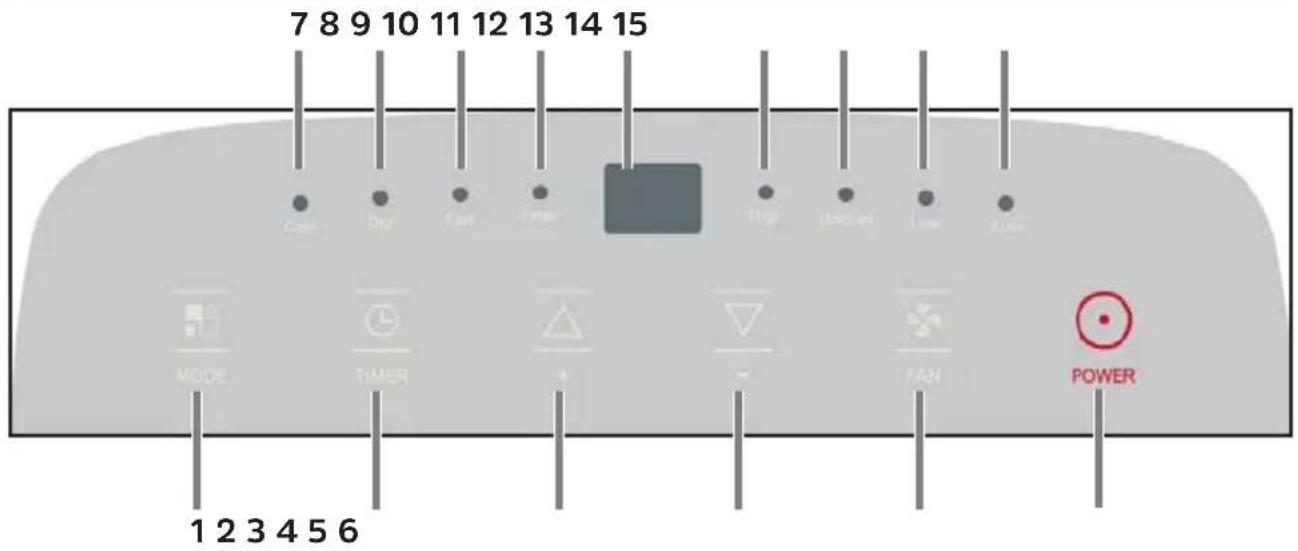
1 Switch operating mode
2 Timer
3 Temperature selection (warmer)
4 Temperature selection (cooler)
5 Blower level
6 On/Off switch
7 Cooling function on
8 Dehumidifier function on
9 Fan on
10 Timer on
11 Display
12 Blower level high
13 Blower level medium
14 Blower level low
15 Automatic air conditioning active
7.2 Switching on and off
Insert the plug into the wall outlet. "-" appears on the display.
Press the POWER button (6) once to switch on the unit.
Press the POWER button again to switch the unit off.

Never turn off the air conditioner by pulling out the power plug. Always switch off the air conditioner first by pressing the POWER button and wait a few minutes before unplugging it. This allows the unit to perform a check cycle and shutdown properly.

Do not switch the air conditioner back on immediately after switching it off - wait a few minutes.
7.3 Cooling mode
The unit is ideal for hot, humid weather when it comes to cooling and dehumidifying the room Dehumidify at the same time.
Press the MODE button (1) several times until "Cool" (7) lights up.
Select the target temperature (18°C to 32°C) by pressing the Temperature selection warmer / cooler (3, 4) buttons until the corresponding value is shown on the display.

After switching on the unit and activating the cooling function, it may take a moment for the compressor to start and the unit to start to cool.
Press the FAN button (5) several times to select the desired fan speed, whereby High, Medium, Low and Auto (automatic control) can be selected. Depending on the fan speed selected, the noise level of the air conditioning unit while in operation will also change. If you prefer the quietest possible operation, select Low.

The most suitable temperature for the room during the summer is between 24^ C and 27^ C. However, it is recommended not to set a temperature that is far below the temperature outside.

Both drain caps (9, 10) should be closed in this mode to allow efficient cooling.
7.4 Dehumidifier mode
The unit is ideal for reducing the room humidity (in spring and autumn, damp rooms, rainy periods, etc.).

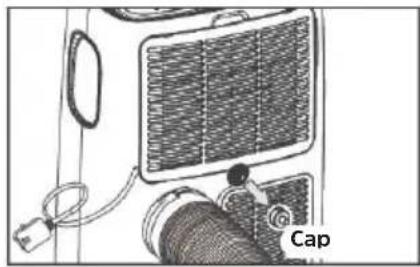
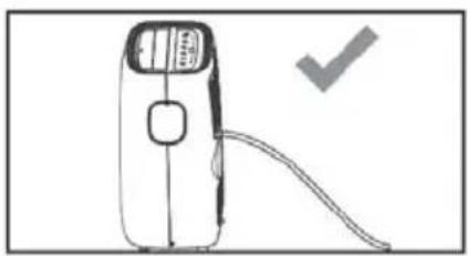
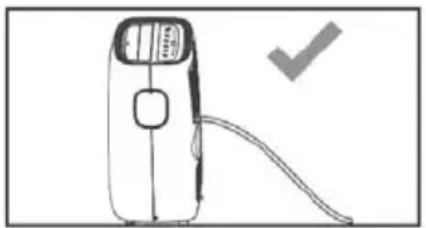
Note that in dehumidifier mode the moisture in the air is reduced. The condensed water is discharged to the outside via the upper drain (10). Direct the water into a suitable container and empty it regularly, depending on the size of the container.
Remove the upper drain cap (1.).
Connect the supplied hose or a suitable hose to the connection (2.) and direct it into a suitable container.
natural_image
Diagram of a car interior showing airflow path and labeled component 'Cap' (no text or symbols beyond label)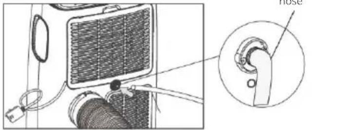
Press the MODE button (1) repeatedly until Dry (8) lights up and, at the same time, the symbol for the automatic fan Auto (15) lights up.

In this mode, the fan speed is selected automatically by the unit and cannot be set manually.

Be careful not to kink the condensate hose.
natural_image
Simple line drawing of a portable device with a handle and cable, no text or symbols present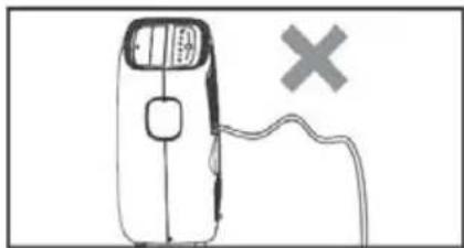
natural_image
Simple line drawing of a handheld device with a cross symbol on the right side (no text or labels)7.5 Fan mode
If you use the unit in this mode, the exhaust hose does not need to be connected.
Press the MODE button (1) several times until Fan (9) lights up. Press the FAN button (5) several times to select the desired fan speed - High, Medium, or Low can be selected.

Automatic control is not available in this mode.
7.6 Automatic mode
In automatic mode, the unit independently decides which mode to use based on the current room temperature:
- Room temperature under 23^ C = Fan mood
- Room temperature over 23^ C = Cooling mode
Press the MODE button (1) several times until all mode LEDs are switched off and a rotating bar appears on the display.

flowchart
graph LR
    A["Step 1: Left loop with arrow"] --> B["Step 2: Downward arrow"]
    B --> C["Step 3: Downward arrow"]
    C --> D["Step 4: Upward arrow"]
    D --> E["Step 5: Downward arrow"]
Press the FAN button (5) several times to select the desired fan speed - High, Medium, or Low can be selected.
8 Timer mode
The timer can be used to automate switching the unit on or off.
Efficient use of the timer mode saves electricity, since the unit is only in operation at the set times.
8.1 Programming the timer
Delayed switching on
First select the mode and the desired settings (fan speed, temperature) while the unit is in operation. Then switch off the unit.
With the unit is switched off, press the TIMER button (2). The timer LED (10) and the number of hours flash on the display.
Within 5 seconds, press the TIMER button again several times to set the hours by which you want to delay switching on the unit.
The timer can be set in 1-hour intervals from 1 hour up to 24 hours.
Approximately 5 seconds after the time is selected, the setting is saved, the timer LED lights up and the display indicates that the unit is in standby mode (--).
After the set time has elapsed, the unit will start up in the last set operating mode.
To delete the setting, press the timer button again. The timer display will turn off.
Delayed turning off
When the unit is switched on, press the TIMER button (2). The timer LED (10) and the number of hours flash on the display.
Within 5 seconds, press the TIMER button again several times to set the hours by which you want to delay switching off the unit.
i The timer can be set in 1-hour intervals from 1 hour up to 24 hours.
Approximately 5 seconds after the time selection, the setting is saved and the timer LED lights up.
After the set time has elapsed, the unit switches to standby mode.
To delete the setting, press the timer button again. The timer display will turn off.
9 Using the remote control
9.1 Inserting the batteries
Open the cover on the battery compartment at the rear of the remote control by pressing gently at the point indicated and sliding open the cover.
Insert the batteries (LR03, AAA, 1.5 V), ensuring that the terminals are the right way round (indicator visible in battery compartment).
Close the battery compartment again.
i Important note on the disposal of batteries: Batteries may contain toxins that are harmful to the environment. Therefore, it is imperative to dispose of batteries according to the legal provisions in force. Never dispose of batteries in the normal household waste. Used batteries can be disposed of at your specialist retailer or at special disposal sites free of charge.
i Ensure that the batteries are kept out of the reach of children. Children could put the batteries into their mouths and swallow them. This could lead to serious injuries. Seek medical advice immediately if this occurs! Therefore ensure that the batteries are out of reach of young children.
i Only operate the unit using the batteries approved for this unit.
Normal batteries must not be charged up. Batteries must not be reactivated by other means, dismantled, heated or thrown into an open fire (risk of explosion!).
i Clean battery contacts and unit contacts before inserting. There is an explosion hazard if a battery is inserted incorrectly!
9.2 Overview
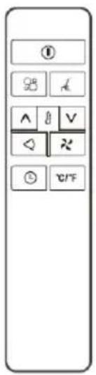
| 1 | Turn On/Off | Fan mode | |
| ^ | Temperature higher | Operating mode | |
| ∨ | Temperature lower | Air outlet | |
| L | Timer mode | Night mode | |
| °C/°F | Selecting temperature units |
Basic operation using the remote control is as described in section „7 Bedienung“. Press the correspondingly labelled button, analogous to the top of the unit.
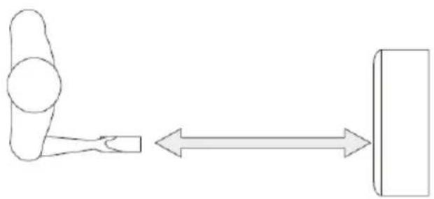
Point the remote control at the top of the air conditioner. Observe the maximum distance of 7 metres.
natural_image
Simple line drawing of a hammer and sickle with an arrow indicating bidirectional movement (no text or symbols)9.3 Activating special functions with the remote control
9.3.1 Ventilation outlet
The upper ventilation outlet opens and closes slightly in a constant rhythm. If you want to lock the air outlet in one position, press the Air Outlet button on the remote control.
Press the button again to automatically adjust the panning.
9.3.2 Changing the temperature unit
Press the Temperature units button to switch the temperature units shown on the display between degrees Celsius and Fahrenheit.
9.3.3 Night mode
In night mode, the display and the LED on the top of the unit are dimmed.
Select cool mode.
Press the Night mode button on your remote control.

The displays are now dimmed and the fan runs at the slowest speed.

In cool mode, the temperature setting is gradually increased to 1^ C above the original target temperature for each of the first 2 hours. The unit then maintains the same temperature for 6 hours and then switches to standby mode.

Night mode is not available in fan or dehumidifier modes.
10 Servicing and maintenance
10.1 Draining the condensation
Over time, condensation will collect in the air conditioning unit's tank. If the tank is full, the unit stops and Ft (= full tank) appears on the display.
Draining the condensation manually:
Remove the plug on the air conditioning unit from the wall socket.
Place a suitable container under the lower condensation drain (9, page 36).
Remove the drain cap and let all the water drain into the collection vessel.
When the water has drained off, put the cap back on the condensation drain.
You can then put the air conditioner back into operation.
Automatically drain the condensation continuously:
In dehumidifier mode, the condensation must be continuously drained to the outside. The upper condensation drain (10, page 36) is provided for this.
Remove the plug on the air conditioning unit from the wall socket.
Place a suitable container under the upper condensation drain (10, page 36).
Remove the drain cap and attach a suitable hose to the drain connection.
The hose should now be directed vertically downwards into the collection vessel. Be careful not to kink the hose.
natural_image
Simple line drawing of a portable device with a handle and cable, no text or symbols present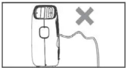
natural_image
Simple line drawing of a handheld device with a cross symbol on the right side (no text or labels)Put the air conditioner back into operation and activate the dehumidifier mode.

In cooling mode, the upper condensation drain must be closed to ensure efficient operation.
10.2 Cleaning the unit

Switch off the unit before cleaning or performing maintenance by pressing the POWER button on the control panel or remote control. Wait a few minutes and then pull the plug out of the wall outlet.
CLEANING THE UNIT
Clean the unit with a slightly damp cloth and then dry it completely with a dry cloth.

Never clean the air conditioner with water. Never use petrol, alcohol or solvents to clean the unit. Never spray insecticides or the like onto the unit.
CLEANING THE FILTER

To ensure that your air conditioner works efficiently, you should clean the filter every week when operating.
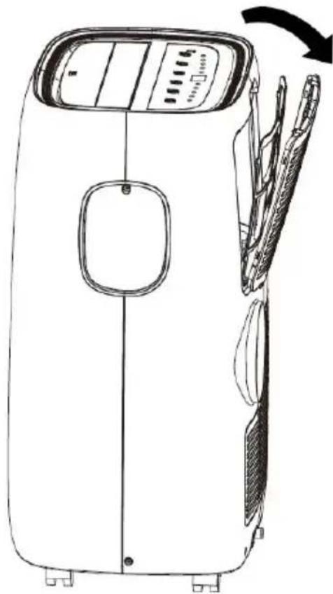
The filter can be removed as shown in the illustration on the right.
Remove dust accumulations on the filter with a vacuum cleaner.
If it is very dirty, immerse it in warm water and rinse several times. The water should be lukewarm.
After washing, let the filter dry completely and put it back in place.

Never use a filter that is still wet. Doing so can damage the unit.

CAUTION!
When the filter housing is open, do not touch the cooling fins inside the unit. These are sharp and can cause cuts.
natural_image
Line drawing of a portable air conditioner unit with front panel and side panels, showing internal components and a black arrow indicating rotation (no text or symbols)10.3 Activities at the start / end of the season
Start of the season:
Check the power cord and plug for damage. Check the basic installation of the unit and the location according to these instructions.
End of the season:
If the air conditioner is not going to be used for an extended period:
Empty the condensation collection container completely and leave the lower drain cap open until the residual water has drained off. As soon as the tank is completely empty and no more water drains out, replace the rubber stopper.
Remove and clean the filter, let it dry completely and then reinsert it.
Remove the batteries from the remote control.
Store the air conditioner in a cool, dry place away from direct sunlight, extreme temperatures and excessive dust.
11 Troubleshooting
| Problem Cause Solution | ||
| The air conditioner does not start / does not switch on. | No power. Check the electrical supply. | |
| Power cord not plugged in. | Plug the power cord into a wall outlet. | |
| Protection circuit activated. | Wait 30 minutes and then try again. If the error persists, contact our service department. | |
| The air conditioner only runs for a short time. | The exhaust hose is kinked or incorrectly connected. | Follow the steps in the operating instructions for connecting the exhaust hose |
| The air outlet / exhaust hose is blocked. | Check the air outlet / exhaust hose for possible dirt contamination. | |
| The air conditioner works but does not cool. | Windows / curtains / drapes are open. | Protect the room from sunlight and close all windows. |
| Other units in the room are causing heat (e.g. television, stoves, hair dryer). | Switch off all additional units in the room. | |
| The exhaust hose was not installed or was not directed outside. | Install the exhaust hose correctly. | |
| The cooling capacity is not suitable for the room in which the air conditioner is being operated. | Pay attention to the technical data of the air conditioner. | |
| The unit emits an unpleasant odour while in operation. | Air filter is blocked or dirty. | Remove the air filter and clean it as per the instructions. |
| After a restart, it takes 3 minutes for the unit to start working again. | The protective circuit of the compressor prevents an immediate start after the unit has been switched off and on again. | Wait 3 minutes. The unit will then work as usual again. |
| The following error messages appear on the display: Lt PF Ft | The self-diagnosis function has detected an error. | Lt - temperature in the room is too low. The de-frost function starts.PF - sensor error. Notify our service departmentFt - condensation tank is full. Empty the tank as described in these instructions. |
12 Technical data
| Cooling performance 9000 BTU/h / 2.6 kW | |
| Modes Cooling, Fan, Dehumidifying, Timer | |
| Temperature range: 18 - 32 °C | |
| Room size 25 m2 | |
| Dehumidification output 26 litres/day | |
| Noise level 53 - 65 dB | |
| Coolant R290 (205g) | |
| GWP coolant 3 | |
| Power consumption - cooling 1 kW/h* | |
| ERR 2.6 (refrigeration coefficient) | |
| Energy efficiency class - cooling A | |
| Intake pressure 1.2 MPa | |
| Outlet pressure 2.3 MPa | |
| Exhaust hose length 1.5 m (max.) | |
| Exhaust hose diameter 15 cm | |
| CO2 equivalent | 0.0006 t |
| Protection class | IPX0 |
| Display | Type: 7 segments, 2 digits |
| Dimensions (WxHxD) | 44 x 69.5 x 32.5 cm |
| Weight | 27 kg |
| Power supply | Mains adapter: internalNominal output: 1200 WFrequency: 50 HzNominal voltage: 220 - 240 V |
| Contents of the Package | Mobile air conditioner unit. Instruction manual, remote control, Exhaust hose and condensate hose, window seal |
*Energy consumption refers to standard test results from a typical environment. Actual energy consumption depends on the location, environment and use of the unit.
13 Legal notices

TechniSat is not liable for product damage due to external influences, wear and tear or improper handling, unauthorised repair, modifications or accidents.

Subject to alterations and printing errors. Version 12/20. Duplication and reproduction only with the publisher's approval. The respective current version of the instructions can be downloaded in PDF format from the download area of the TechniSat Homepage at www.technisat.de.

TechniSat and TECHNIPOLAR 2 S are registered trademarks of:
Names of companies, institutions or brands mentioned are trademarks or registered trademarks of their respective owners.
13.1 Service instructions

This product is quality-tested and provided with the legally-specified warranty period of 24 months from the date of purchase. Please keep your receipt as proof of purchase. In the event of warranty claims, please contact the product dealer.

Note!
For questions and information or if there is a problem with this unit, our Technical Hotline is available:
Mon. - Fri. 8:00 am - 6:00 pm at tel.:
+49 (0) 3925 9220 1800.

Repairs can also be requested directly online at www.technisat.de/reparatur.
If you need to return the unit, please use the following address only:
39418 Stassfurt, Germany
Instrukcjaobstugi
TECHNIPOLAR 2 S
natural_image
Line drawing of a portable air conditioner unit with control panel and side door (no text or symbols)2 Wstep
Szanowny Kliencie,
natural_image
Diagram of a cylindrical object with internal parallel grooves, marked with arrows and number 1 (no text or symbols on the object itself)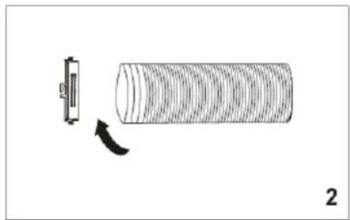
natural_image
Diagram showing a cylindrical object with a curved arrow indicating rotation or change, next to a small rectangular component (no text or symbols)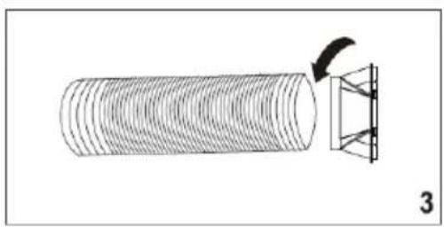
natural_image
Diagram showing a cylindrical object with a curved arrow pointing to a geometric structure, labeled '3' (no text or symbols on the diagram itself)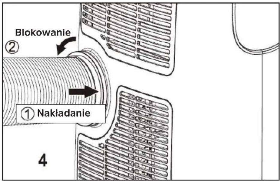
natural_image
Close-up of a hand cleaning a window frame with corrugated metal lining (no text or symbols visible)natural_image
Black-and-white photo of a hand opening a window with blurred trees in the background (no text or symbols visible)natural_image
Close-up of a hand holding a small object near a window (no visible text or symbols)natural_image
Close-up of a hand holding a white plastic clip against a wall-mounted fixture (no visible text or symbols)natural_image
Close-up of a window with visible door and window frame, no text or symbols presentnatural_image
Black and white photo of a window with a door, showing the exterior and side panels (no text or symbols visible)natural_image
Close-up of a hand holding a thin, thin object against a plain background (no text or symbols visible)natural_image
Close-up of a striped fabric or cloth hanging from a glass window (no text or symbols visible)natural_image
Diagram of a device with a curved pipe and diagonal line, no text or symbols present7 Obsługa
natural_image
Technical diagram of a vehicle's internal components, including a fan and hose assembly (no text or symbols)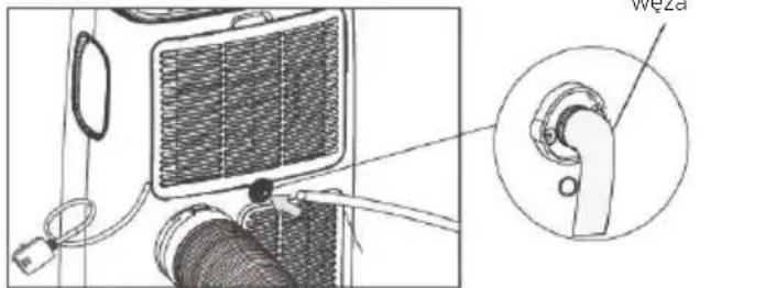
natural_image
Simple line drawing of a portable device with a handle and cable, no text or symbols present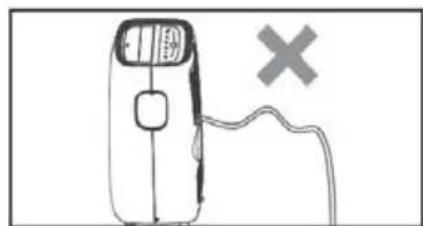
natural_image
Simple line drawing of a handheld device with a switch and a cross symbol, no text or labels present.7.5 Tryb wentylacji
natural_image
Simple line drawing of a hammer and sickle with an arrow indicating bidirectional movement (no text or symbols)natural_image
Simple line drawing of a portable device with a handle and cable, no text or symbols present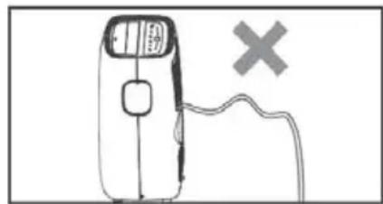
natural_image
Simple line drawing of a car with a switch and a cross symbol, no text or labels presentnatural_image
Line drawing of a portable air conditioner unit with front panel and side panels, showing internal components and a black arrow indicating rotation (no text or symbols)

- CONTENTS
- Bedienungsanleitung
- TECHNIPOLAR 2 S
- Vorwort
- Bedienung
- Lüftermodus
- Preface
- Dear Customers,
- Index
- Safety instructions
- Signs and symbols used
- In this instruction manual and on the unit:
- Intended use
- Safe use of air conditioners
- WARNING!
- IMPORTANT - EARTHING METHOD
- ELECTRICAL CONNECTIONS
- Disposal instructions
- Illustrations
- Installation instructions
- Exhaust air discharge
- Installing the window kit
- Site of installation
- Operation
- Switching on and off
- Cooling mode
- Dehumidifier mode
- Fan mode
- Automatic mode
- Timer mode
- Programming the timer
- Delayed switching on
- Delayed turning off
- Using the remote control
- Inserting the batteries
- Overview
- Activating special functions with the remote control
- Ventilation outlet
- Changing the temperature unit
- Night mode
- Servicing and maintenance
- Draining the condensation
- Draining the condensation manually:
- Automatically drain the condensation continuously:
- Cleaning the unit
- CLEANING THE UNIT
- CLEANING THE FILTER
- CAUTION!
- Activities at the start / end of the season
- Start of the season:
- End of the season:
- Troubleshooting
- Legal notices
- Service instructions
- Instrukcjaobstugi
- Wstep
- Szanowny Kliencie,
- Obsługa
- Tryb wentylacji
Brand : TECHNISAT
Model : Technipolar 2 S
Category : Air-conditioner