
Generate 3 - Synthesizer Joranalogue - Free user manual and instructions
Find the device manual for free Generate 3 Joranalogue in PDF.


| Product Type | Eurorack Synthesizer Module |
| Brand | Joranalogue |
| Model | Generate 3 |
| Module Format | Doepfer A-100 'Eurorack' compatible, 3U, 12 HP, 30 mm deep (inc. power cable) |
| Dimensions (H x W x D) | 128.5 x 60.6 x 43 mm |
| Weight (Module) | 175 g |
| Weight (Incl. Packaging) | 250 g |
| Current Draw (+12V) | 130 mA |
| Current Draw (-12V) | 115 mA |
| Power Protection | Reverse polarity (MOSFET) |
| Input Impedance | 100 kΩ (all inputs) |
| Output Impedance | 0 Ω (compensated, all outputs) |
| Main Functions | Voltage controlled oscillator with through-zero linear FM, through-zero phase modulation, harmonics generator with fundamental, even, odd timbral channels, reset/flip sync, exponential FM, V/Oct tracking |
| Synthesis Type | Analog, triangle-core VCO |
| Number of Outputs | 5 (Core, Fundamental, Even, Odd, Full) |
| Number of CV Inputs | 7 (Through-zero FM, V/Oct, Exponential FM, Reset, Flip, Phase, 3 Harmonic CVs) |
| Controls | Frequency range switch (VCLFO/VCO), Coarse and Fine frequency knobs, FM polariser knob, Bias and AC switches, Phase knob, 3 Harmonic level knobs, V/Oct trimmer |
| LED Indicators | Output socket LEDs (positive: red, negative: blue) |
| Front Panel | Milled 2 mm aluminium, non-erasable graphics |
| Maintenance | Keep dry, avoid static discharge; clean with dry cloth; disconnect power before handling |
| Safety | Use only Eurorack power supply; ensure correct polarity; module can get warm during operation |
| Spare Parts & Repairability | Contact dealer or support@joranalogue.com for servicing; no user-serviceable parts |
| Included Accessories | Product card, 16-to-10-pin Eurorack power cable, 2 x M3 hex screws, 2 x nylon washers, hex key, cotton bag |
| Support | support@joranalogue.com, include serial number |
Frequently Asked Questions - Generate 3 Joranalogue
User questions about Generate 3 Joranalogue
0 question about this device. Answer the ones you know or ask your own.
Ask a new question about this device
Download the instructions for your Synthesizer in PDF format for free! Find your manual Generate 3 - Joranalogue and take your electronic device back in hand. On this page are published all the documents necessary for the use of your device. Generate 3 by Joranalogue.
USER MANUAL Generate 3 Joranalogue
Any signal can be expressed in terms of a few parameters: frequency, phase, amplitude and timbre. It is through modulation of these aspects that synthesists create electronic sound. With Generate 3, it is now possible to create a signal and control all its parameters by through-zero modulation within a single 12 HP wide module.
Everything starts with the exceptionally precise triangle-core voltage controlled oscillator (VCO) at the module's heart. Through-zero linear frequency modulation (FM) enables rich yet pitch-stable FM sounds, by allowing the oscillator to run backwards into 'negative frequencies'.
The resultant triangle wave is then processed by the through-zero phase modulator, providing a total phase shift range of 900^ . Phase modulation offers an interesting alternative for FM, as it enables deep FM-type tones without actually changing the oscillation frequency.
The timbre of a signal is determined by its harmonic content. This full set of harmonics can be grouped into three main parts: the fundamental, even and odd harmonics.
Generate 3's harmonics generator separates out these three timbral 'channels'. By adjusting their relative amplitudes, a vast array of different waveforms can be created, including but not limited to the classic sine, saw and square waves.
While the amplitudes can be adjusted manually, each timbral channel supports through-zero amplitude modulation, also known as balanced or ring modulation. When audio-frequency modulation signals are applied, the harmonics become 'split', enriching the spectrum.
In addition to all the usual analogue synthesis techniques, the extensive set of modulation options makes Generate 3 especially suited for exploring multiphonic synthesis: a monophonic source creating a complex timbre, much like throat singing, yet by electronic means.
CONTENTS
In the Generate 3 box, you'll find:
- Product card, stating serial number and production batch.
■ 16-to-10-pin Eurorack power cable. - Mounting hardware: two black M3 x 6 mm hex screws, two black nylon washers and a hex key.
- The Generate 3 module itself, in a protective cotton bag.
If any of these items are missing, please contact your dealer or support@joranalogue.com.
CONTROLS & CONNECTIONS
1 FREQUENCY RANGE SWITCH
This switch determines over which frequency range Generate 3 will operate: low frequency (VCLFO) or audio frequency (VCO).
2 COARSE AND FINE FREQUENCY KNOBS
The oscillation frequency is determined by these knobs. In the audio frequency mode, with the fine knob centred and at default through-zero FM settings, the coarse knob has a range of 22 Hz to 22 kHz at the fundamental signal output. The fine knob's range is 5% of the coarse knob (6 semitones in audio mode).
In low frequency mode, the total range is 2.8 mHz (a period of 6 minutes) to 180 Hz, with 1 Hz when both knobs are centred.
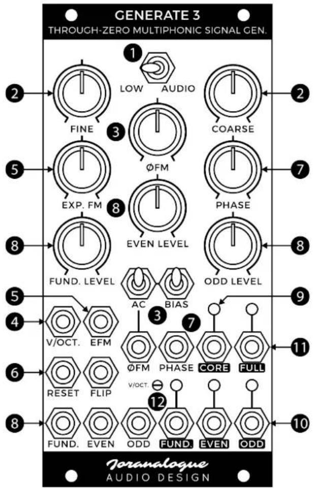
3 THROUGH-ZERO FM INPUT, KNOB AND AC AND BIAS SWITCHES
An internal through-zero FM voltage directly controls the VCO core, determining the overall range of the exponential frequency modulation. For example, the low and audio ranges mentioned earlier assume a through-zero FM voltage of +5 V.
Increasing or decreasing this voltage has a corresponding effect on the frequency. But unlike standard linear FM, the voltage can also be negative, causing the oscillator to flip direction and run backwards. This allows for incredibly deep and dramatic FM sounds.
0 V will cause the VCO to stop. However, since a +5 V normalisation is present on the through-zero FM socket, it is not necessary to plug in an external voltage for the VCO to oscillate. Set the polariser knob to the maximum setting and both bias and AC switches off, and the module will run within the selected range (low/audio). This is considered the default configuration.
The knob can then be used to apply linear detuning, through the zero point and into the negative realm, or adjust the modulation depth if an external through-zero FM signal is applied.
The bias switch, when enabled, then adds a +5 V offset to this modulation. This makes it easy to toggle between through-zero FM (bias off, up) and normal linear FM (bias on, down). In the default configuration with no modulation, the effect of enabling the bias is a doubling in frequency, or an increase in pitch of one octave.
Enable the AC switch to AC-couple the LFM input. This rejects any DC offset or very low frequency content that may be present in the modulation signal, preventing a fundamental pitch shift from appearing during audio rate modulation. Note that this will also remove the normalised +5 V that is present on the through-zero FM socket by default.
4 VOLT PER OCTAVE FM INPUT
This input is used to modulate the frequency in an exponential fashion, with a standard 1 volt per octave response, to create accurate pitches. In the low range, the sensitivity is increased to approximately 0.66 volt per octave.
5 EXPONENTIAL FM INPUT AND KNOB
This second exponential FM input includes a polariser knob to set the modulation depth, with 0 in the centre, +1 volt per octave maximum and -1 volt per octave minimum in audio mode. In low mode, the sensitivity is increased to approximately 0.66 volt per octave.
6 RESET AND FLIP INPUTS
In addition to the through-zero and exponential FM, two types of oscillator synchronisation are available: reset (hard sync) and flip (soft sync).
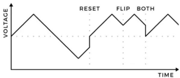
A rising edge on the reset input causes the VCO output voltage to instantaneously go to 0 V. Oscillation will then resume as before. On the other hand, the flip input merely flips the triangle direction (rising or falling) on a rising edge.
Both sync types have a very different effect to the VCO and thus yield different sonic results. Reset sync is considered 'harder' since the fast edges caused by the instantaneous resets create high harmonic content. Flip sync is free from these fast edges, and has a 'softer' sound as a result.
The two sync types can be combined at will and affect all outputs.
line
| TIME | VOLTAGE | |---|---| | 0 | 0 | | Peak 1 | 1 | | Peak 2 | 0 | | Peak 3 | -1 | | Peak 4 | 0 | | Peak 5 | 1 | | Peak 6 | 0 | | Peak 7 | -1 | | Peak 8 | 0 | | Peak 9 | 1 | | Peak 10 | 0 | | Peak 11 | -1 | | Peak 12 | 0 | | Peak 13 | 1 | | Peak 14 | 0 | | Peak 15 | -1 | | Peak 16 | 0 | | Peak 17 | 1 | | Peak 18 | 0 | | Peak 19 | -1 | | Peak 20 | 0 |7 PHASE INPUT AND KNOB
Generate 3's phase modulator allows the phase of the timbral channels to be shifted over a wide range. The phase can either lead or lag with respect to the 0^ reference; thus, this form of modulation is through-zero as well.
With the phase input socket left unpatched, the knob will adjust the phase manually. Once a phase modulation signal is applied, the knob becomes a bipolar attenuator. The sensitivity is 90^/V , with a maximum phase offset of ±450^ .
Since phase is a relative parameter, any stationary phase setting will sound the same as any other. However, when the phase continually changes over time, a perceived pitch change occurs, despite the core oscillation frequency remaining constant. Thus, PM provides an alternative to through-zero FM for creating 'FM sounds'. Generate 3 allows both modulation types to be used simultaneously.
In addition, shifting the phase will change the effect of the sync inputs on the timbral channels, as the starting points of the waveforms will diverge from the VCO core reference.
8 HARMONIC KNOBS AND INPUTS
The level and polarity of each of the three timbral channels (fundamental, even and odd) is controlled by these knobs and CV inputs. The knobs are bipolar, with a channel amplitude of 10 V_pp in the maximum setting, 0 in the centre and 10 V_pp , with inverted polarity minimum.
Once a cable is plugged into any of the CV sockets, the corresponding knob functions as a bipolar attenuator for the modulation signal. Since the channel amplitude controllers are balanced modulators rather than conventional VCAs, through-zero amplitude modulation is possible, also known as balanced or ring modulation.
9 CORE OUTPUT
This is the 10 V_pp triangle wave output straight from Generate 3's VCO core. It is not affected by the phase modulator. Also note that it is at half the frequency of, so one octave below, the fundamental output, and thus can be used as a sub-octave signal.
The LEDs at the output sockets show the real-time output voltages, lighting up red for positive and blue for negative.
10 HARMONIC OUTPUTS
The output signal for each timbral channel is available from these sockets.
The fundamental channel consists of a sine wave, with any overtones suppressed as much as possible.
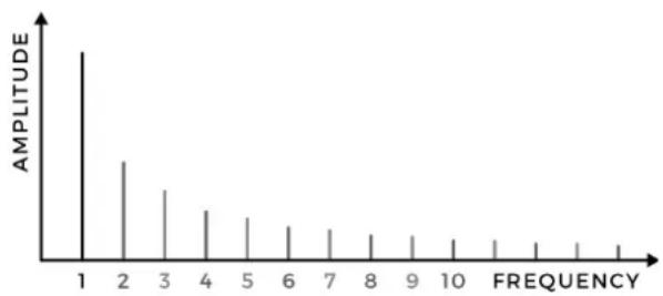
The even signal is a saw wave at twice frequency, thus only containing even harmonics with respect to the fundamental ( 2^nd , 4^th , 6^th etc.), becoming weaker as the harmonic number increases.
The odd channel only contains odd harmonics with respect to the fundamental, excluding the fundamental itself ( 3^rd , 5^th , 7^th etc.), becoming weaker as the harmonic number increases.
11 FULL OUTPUT
The three timbral channels are also mixed together into this output, creating a full-spectrum signal containing all harmonics.
bar
| FREQUENCY | AMPTITUDE | |---|---| | 1 | High peak at 1 | | 2 | Medium peak at 2 | | 3 | Medium peak at 3 | | 4 | Medium peak at 4 | | 5 | Medium peak at 5 | | 6 | Medium peak at 6 | | 7 | Medium peak at 7 | | 8 | Medium peak at 8 | | 9 | Medium peak at 9 | | 10 | Medium peak at 10 | | Frequency | Low amplitude (approx.) |12 VOLT PER OCTAVE TRIMMER
This trim potentiometer is used to calibrate the module's pitch tracking. Since it is accessible from the front panel, calibration can be easily performed without removing the module from the system. Each module is individually calibrated during production; do not adjust this trimmer if not needed.
Should you find your Generate 3 to be out of tune, set the range switch to the audio range, the coarse frequency knob to about 20 % of its range (9 o'clock), and the fine knob in the centre position.
Make sure Generate 3 has been powered for at least 20 minutes at a stable ambient temperature. Now connect the fundamental output to a calibrated digital tuner. The volt per octave input should be switched between 0 V and a precision +5 V source, toggled automatically or by hand. Leave all other inputs unpatched.
Using a dedicated trimming tool or standard 2.5 mm flat screwdriver, adjust the trimmer until the interval between both states is exactly 5 octaves.
PATCH IDEAS
CLASSIC WAVEFORMS
Apart from a vast array of complex waveforms, Generate 3 can also create the classic set of subtractive synthesiser waves: sine, triangle, square and saw.
The sine wave is available from the fundamental output and triangle from the core output.
To create a square wave with standard 10 V_pp amplitude at the full output socket, set the fundamental level knob to 100% (fully clockwise), the even level off (centre position) and the odd level to 80% (approximately 4 o'clock).
The even output signal is a saw wave at double frequency. For a 10 V_pp saw wave at the full output and the fundamental frequency, set the fundamental to 50 % and the two other channels to 40 %.
WHITE NOISE GENERATOR
While Generate 3 is primarily designed to create clean and reliable waveforms, you can push the circuit beyond its limits using feedback patching. Experiment sending outputs to inputs to create many surprising, complex and often unstable sounds.
One feedback patch in particular makes use of the module's high speed and inherent analogue instabilities to create white noise. Simply patch the even output to the phase modulation input and set all knobs to their maximum settings. A 10 V_pp noise signal can now be found at the fundamental output. Vary the frequency to 'tune' the noise.
TIME-SHIFTED RATIOMETRIC RHYTHMS
The outputs waveforms are at multiple frequencies of each other: the fundamental is twice as fast as the core, and even is twice as fast as the fundamental. This relationship can be used in low mode to create ratiometric rhythms: if one core cycle would be considered a bar, then a fundamental cycle represents half notes and an even cycle quarter notes.
The output waveforms can be used to drive various rhythmic elements within a patch: envelopes, drum sounds etc. Depending on the destination, you may need to process the signals through comparators first.
By shifting the phase, the starting point for the half and quarter notes can be moved at will. Use the reset input to perfectly synchronise the rhythms to an external tempo clock signal. The variable waveforms at the full output provide a plethora of complex rhythms to experiment with.
DECAYED HARMONICS
Create ‘filtered’ synth lines using a separate decay envelope for each timbral channel, all triggered together by a sequencer. Use the sequencer's V/oct. output to control Generate 3's pitch.
By then adjusting the decay times, the timbral parts will decay at different rates, giving the illusion of various filter sweeps on the full output.
SPECIFICATIONS
MODULE FORMAT
Doepfer A-100 'Eurorack' compatible module 3 U, 12 HP, 30 mm deep (inc. power cable)
Milled 2 mm aluminium front panel with non-erasable graphics
MAXIMUM CURRENT DRAW
+12 V: 130 mA
-12 V: 115 mA
POWER PROTECTION
Reverse polarity (MOSFET)
I/O IMPEDANCE
All inputs: 100 kΩ
All outputs: 0 Ω (compensated)
OUTER DIMENSIONS (H X W X D)
128.5 x 60.6 x 43 mm
MASS
Module: 175 g
Including packaging and accessories: 250 g
SUPPORT
As all Joranalogue Audio Design products, Generate 3 is designed, manufactured and tested with the highest standards, to provide the performance and reliability music professionals expect.
In case your module isn't functioning as it should, make sure to check your Eurorack power supply and all connections first.
If the problem persists, contact your dealer or send an email to support@joranalogue.com. Please mention your serial number, which can be found on the product card or on the module's rear side.
With compliments to the following fine people, who helped to make Generate 3 a reality!
Ben 'DivKid' Wilson Björn Jauss
Boris Uytterhaegen Gregory Delabelle
Jan D'Hooghe Jérémy Bocquet
Everyone at Wired Electronics
Generate 3 User Manual version 2019-11-26
21 ^st Century Analogue Synthesis—Made in Belgium
© 2019
Joranologue AUDIO DESIGN
info@joranalogue.com https://joranalogue.com/
- CONTENTS
- CONTROLS & CONNECTIONS
- FREQUENCY RANGE SWITCH
- COARSE AND FINE FREQUENCY KNOBS
- THROUGH-ZERO FM INPUT, KNOB AND AC AND BIAS SWITCHES
- VOLT PER OCTAVE FM INPUT
- EXPONENTIAL FM INPUT AND KNOB
- RESET AND FLIP INPUTS
- PHASE INPUT AND KNOB
- HARMONIC KNOBS AND INPUTS
- CORE OUTPUT
- HARMONIC OUTPUTS
- FULL OUTPUT
- VOLT PER OCTAVE TRIMMER
- PATCH IDEAS
- CLASSIC WAVEFORMS
- WHITE NOISE GENERATOR
- TIME-SHIFTED RATIOMETRIC RHYTHMS
- DECAYED HARMONICS
- SPECIFICATIONS
- MODULE FORMAT
- MAXIMUM CURRENT DRAW
- POWER PROTECTION
- I/O IMPEDANCE
- OUTER DIMENSIONS (H X W X D)
- MASS
- SUPPORT
Brand : Joranalogue
Model : Generate 3
Category : Synthesizer