
Masterline MVX1 - Switch KVM-TEC - Free user manual and instructions
Find the device manual for free Masterline MVX1 KVM-TEC in PDF.


| Type | KVM Extender (Local and Remote units) |
| Model | Masterline MVX1 / MVX1-F |
| Dimensions (each unit) | 97.5 x 41 x 103.5 mm (3.83 x 1.57 x 4.7 in) |
| Weight (local unit) | 302 g (0.66 lbs) |
| Weight (remote unit) | 291 g (0.64 lbs) |
| Power supply input | 100-240 V AC, 50/60 Hz |
| Power supply output | 12 V DC, 1 A (external adapter) |
| Power consumption (each) | 6 W (excluding attached USB devices) |
| Operating temperature | 0 °C to 45 °C (32 °F to 113 °F) |
| Storage temperature | -25 °C to 80 °C (-13 °F to 176 °F) |
| Relative humidity (operating) | Max. 80% (non-condensing) |
| Casing material | Anodized aluminum |
| Expected product life | 82,820 hours (9.5 years) |
| Laser class (MVX1-F only) | Class 1 Laser Product (DIN 40008/EN, VDE 0837) |
| Video interface | DVI-D (DVI-In on local, DVI-Out on remote) |
| Audio support | Audio In/Out (stereo jack) on both units |
| USB ports | 1x USB (local for host), 1x USB (remote for keyboard/mouse) |
| KVM link connector | RJ45 for CAT5e/6/7 or fiber (MVX1-F with SFP) |
| Maximum distance (CATx) | Up to 150 m (492 ft) with CAT5e/6/7 |
| Maximum distance (fiber, multimode) | Up to 500 m (1640 ft) |
| Maximum distance (fiber, single-mode) | Up to 20 km (12 mi) optional |
| Supported resolutions | Up to 1920x1200 (fixed DDC presets available) |
| LED indicators | Status LED (red/orange/green), RJ45 socket LEDs (yellow/green) |
| Warranty | 2 years (extendable to 5 years) |
Frequently Asked Questions - Masterline MVX1 KVM-TEC
User questions about Masterline MVX1 KVM-TEC
0 question about this device. Answer the ones you know or ask your own.
Ask a new question about this device
Download the instructions for your Switch in PDF format for free! Find your manual Masterline MVX1 - KVM-TEC and take your electronic device back in hand. On this page are published all the documents necessary for the use of your device. Masterline MVX1 by KVM-TEC.
USER MANUAL Masterline MVX1 KVM-TEC

Masterline MVX
6701 SET
6701L CPU/LOCAL
6701R CON/REMOTE
Masterline fi ber MVX-F
6801 SET
6801L CPU/LOCAL
6801R CON/REMOTE
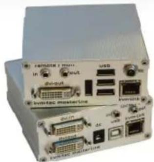
natural_image
Front view of a beige electronic device with ports and connectors (no visible text or symbols)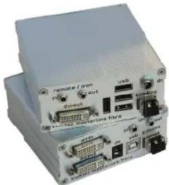
natural_image
Exterior view of a white electronic device with ports and connectors (no visible text or symbols)TABLE OF CONTENTS
TABLE OF CONTENTS
1. Introduction 6
1.1 Intended Use 6
1.2 Safety Instructions 7
1.3 Technical Specifications 9
1.4 Product Elements 10
1.5 Meaning of LED indicators 12
2. Installation of the extender 13
2.1 Unpacking and checking the contents 13
2.2 Mounting options 14
2.2.1 Mounting pads and rubber feet 14
2.2.2 Mounting kits (optional) 14
2.3 Installing the extender 15
2.4 Startup 20
2.5 Replacing the SFP module 20
2.6 Removing a CATx cable 21
2.7 Removing a fiber cable 21
3.1 How to access the main menu 22
3.2 Status Menu 23
3. Extender menu/settings 23
TABLE OF CONTENTS
3.3 How determine the current Firmware version 24
3.4 How to perform a firmware update 25
3.4.1 update via a bitmap image 26
3.4-2 update with usb stick 27
3.4.3 Performing autoupdate 30
3.4.4 Performing network update 31
3.5 unlock an upgrade 32
3.6 How to enable or disable the USB memory upgrade 33
3.7 How to define what DDC information by the PC 34
3.8 How to change the network settings 34
3.9 How to change the extender settings 35
3.9.1 How to optimize VGA preferences 37
3.9.2 How to enable or disable the USB compatibility mode 38
3.9.3 How to set the audio volume 39
3.9.4 How to set the baud rate for the RS232 40
3.9.5 How to show the last received image 41
3.9.6 How to turn on or off monitor synchronization 42
3.9.7 How to lock the main menu 43
3.9.8 How to use power saving mode 44
3.9.9 How to select your type of keyboard 45
TABLE OF CONTENTS
3.9.10 How to change the keyboard fallback mode 46
3.9.11 How to change keyboard hortcuts 47
3.9.12 How to close the Extender Settings menu 47
3.10 How to switch between different computers 48
3.11 How to share videos 49
4. Network Settings 51
4.1 How to access the Network Settings menu (Master View and 51
4.2 How to force disconnect or select a workstation from the current connected devices 53
4.3 How to manage user details, rights and groups 55
4.4 How to view the status of all remote units 58
4.5 How to view the status of all local units 60
4.6 How to set up dual-head or multi-head systems 62
4.7 How to enable user groups and rights and login access 64
4.8 How to auto-connect to a free computer after an interruption 65
4.9 How to set up a private connection 66
4.10 How to enable the User-PC Binding mode 67
4.11 How to enable the disconnect on PC Power Down option 68
4.12 How to hide info display 69
4.13 How to reconnect on startup 70
TABLE OF CONTENTS
4.14 Video Sharing 70
4.15 How to set the password timeout 71
-
Maintenance and care 72
-
troubleshooting 72
-
Troubleshooting 73
-
Disposal 73
-
Warranty 74
-
Support 74
-
Declaration of Conformity 75
11.1 Requirements for CAT5e/6/7 cables 77
- Requirements for cables 77
11.3 Requirements network switch 78
11.2 Requirements fibER cables 78
11.2.1 Multi-Mode (standard) 78
11.2.2 Single-Mode (optional) 78
-
Requirements Network Switch 78
-
First Aid 80
-
Extended warranty 81
-
Notes 82
1. INTRODUCTION
Congratulations on the purchase of your new Masterline MVX1/MVX1-F KVM Extender. You have bought a high quality extender. These instructions are part of this product. They contain important information regarding safety, use and disposal for every user of the Masterline MVX1 and MVX1-F KVM Extender. Please familiarise yourself with the information within prior to using your product. Use the product only in the manner as described and for the areas of application as stated. When passing the product to a third party be sure to also supply all instructions and other relevant documentation. Following proper use and maintenance, your Masterline MVX1/MVX1-F KVM Extender will bring you joy for many years to come.
1.1 INTENDED USE
This product is intended to be used as a device to increase the distance that a keyboard, monitor and mouse can be placed from a computer. This product is intended for professional use. The product should not be used in potentially explosive environments.
The product may only be used according to the instructions as described in this manual. All use, other than that described in this manual, is seen as unintended use. Modifications in the course of technological progress are reserved. In these user instructions the Masterline MVX1/MVX1-F KVM Extender is referred to as 'product' or 'extender'. The MVX1/PC is referred to as the 'local unit' and the MVX1/Monitor is referred to as the 'remote unit'.
1. INTRODUCTION
1.2 SAFETY INSTRUCTIONS
WARNING! Read and understand all safety instructions.
- Follow all the instructions. This will avoid accidents, fire, explosions, electric shocks or other hazards that may result in damage to property and/or severe or fatal injuries. Please ensure that everyone who uses the product has read and followed these warnings and instructions.
- Keep all safety information and instructions for future reference and pass them on to subsequent users of the product.
- The manufacturer is not liable for cases of material damage or personal injury caused by incorrect handling or non-compliance with the safety instructions. In such cases, the warranty will be voided.
- This product is not intended for use by persons (including children) with restricted physical, sensory or intellectual capability or lack of experience and/or knowledge, unless they are supervised by a person who is responsible for their safety or provides them with instructions on how to use the product.
- DANGER! Not for use in potentially explosive environments.
- DANGER! Be vigilant at all times, and always take care around this product. Do not use electrical equipment if you are lacking in concentration or awareness, or are under the influence of drugs, alcohol or medication. Even a moment of inattentiveness can lead to serious accidents and injuries when using electrical equipment. Check the product and the cables for any damage before use. If there is any visible damage, a strong odour, or excessive overheating of components unplug all the connections immediately and stop using the product.
• DANGER! The MVX1-F KVM Extender is a Class 1 Laser Product 1 according to DIN 40008/EN and VDE 0837.
- If the product is not installed and used in accordance with this manual, it may cause disruptive interference with radio or television reception or affect other electronic products in residential areas.
- Use shielded cables only to connect the components in order to avoid such interference. Non-compliance invalidates the permission to operate this product.
- Only the mains adapter included with the product should be used as the power supply. Do not use other adapters.
- Prior to connecting to the mains, make sure your local mains voltage matches the rating indicated on the product.
- The product must be connected to a permanent and earthed AC wall socket.
1. INTRODUCTION
- Protect cables from being strained, pinched or buckled and place them in a way to prevent people from tripping over the cord.
- In particular, ensure to avoid damage to the mains adapter.
- Use the product with a suitable, properly installed and easily accessible mains power socket. Make sure the product can be disconnected from the power socket at all times.
- Unplug the product during electrical storms or when not in use.
- DANGER! Never touch the adapter with wet hands.
- Use the product within the specified performance limits.
- Keep the product away from flammable materials such as curtains and drapes.
- Protect the mains adapter from use by third parties (particularly children). Keep the unused mains adapter in a dry, elevated or locked location away from children.
- Do not place the product near heaters.
- Do not drop or hit the product.
- Unplug all connections before cleaning the product. Do not use wipes or chemicals as these could damage the surface. Wipe the housing with a damp cloth. Electrical/electronic parts must not be cleaned.
- Alterations to the product and technical modifications are not permitted.
1. INTRODUCTION
1.3 TECHNICAL SPECIFICATIONS
Type: KVM Extender (local unit and remote unit)
Model: Masterline MVX1/MVX1-F KVM Extender
Power supply input voltage: 100 - 240 V; 50/60 Hz AC
Power supply output: 12V; 1A (external power supply)
Power requirement: 6W per extender (excluding attached USB devices)
Operating temperature range: 0 °C to 45 °C / 32 °F to 113 °F
Storage temperature range: -25 °C to 80 °C / -13 °F to 176 °F
Relative humidity: max. 80% (non-condensing)
Storage humidity: max. 80% (non-condensing)
Casing Material: Anodized aluminium
Dimensions: approx. 97,5 x 41 x 103,5 mm / 3.83x 1.57 x 4.7 inch "
Weight: local unit 302g/0.66lbs.
remote 291g/0.64lbs
Expected product life: 82 820 hours / 9.5 years
Laser MVX1-F: Class 1 Laser Product 1 according to DIN 40008/EN and VDE 0837
1. INTRODUCTION
1.4 PRODUCT ELEMENTS
Local Extender (CPU)
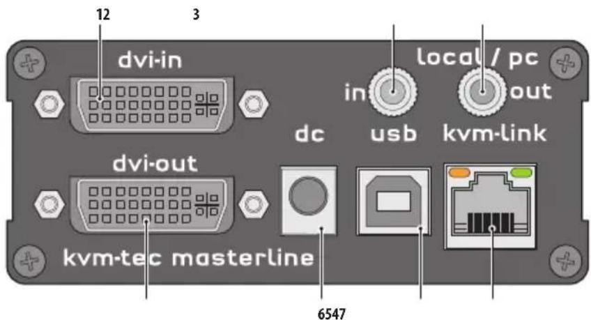
Nr. Name Function
1 dvi-in DVI connection to PC
2 in Audio In from PC
3 out Audio Out to PC
4 kvm-link/ RJ45 socket Connection for CAT5/6/7 cable or fibre cable
5 usb USB connection
6 dc Connection for 12 V power supply
7 dvi-out DVI connection to monitor
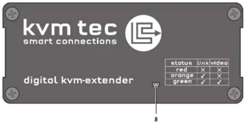
8 Power/Status LED Displays the status of the extender
1. INTRODUCTION
Remote Extender (CON)
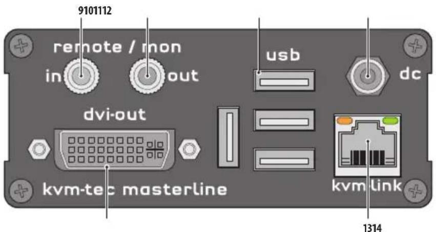
Nr. Name Function
9 in Audio In from microphone etc.
10 out Audio Out to speakers etc.
11 usb USB connections (e.g. for keyboard and mouse)
12 dc Connection for 12 V power supply
13 kvm-link/ RJ45 socket Connection for CAT5/6/7 cable or fibre cable
14 dvi-out DVI-D connection to monitor
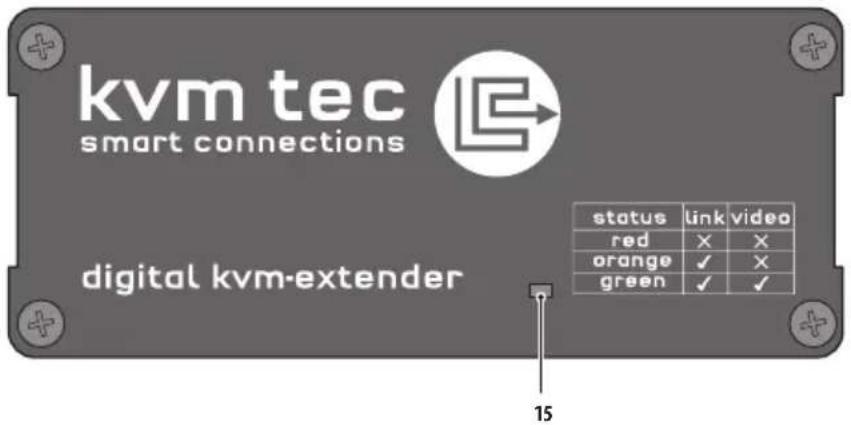
15 Power/Status LED Displays the status of the extender
1. INTRODUCTION
1.5 MEANING OF LED INDICATORS
The Status LED (8/15) can light red, orange or green. Table 1 shows the meaning of each colour. Also see chapter Troubleshooting.
| Normal Operation | ||||||||
| Colour Blinking Physical Link | Active Connection | Video Extended | USB Initialisation | UBS Data Received | Identify Command | Autoupdate Mode | ||
| Main LED | ||||||||
| Red - Yes No Update Failed | ||||||||
| Red Slow No No | ||||||||
| Orange | - Yes Yes No | |||||||
| Orange | Fast | Update in Progress | ||||||
| Green | - | Yes | Yes | Yes | Update Succeeded | |||
| Green | V. fast | Yes** | ||||||
| Red/Green | V. fast | Yes | ||||||
| RJ45 Socket LEDs * | ||||||||
| Yellow | - No | |||||||
| Yellow | Slow Yes | |||||||
| Green | - | Yes | ||||||
| Green | V. fast | Yes | ||||||
* MVX only ** Rem. Only
Table 1: Meaning of LED indicators
2. INSTALLATION OF THE EXTENDER
2.1 UNPACKING AND CHECKING THE CONTENTS
Before using the product for the first time it should be checked for damage. In case of damage due to transport inform the carrier immediately. Before delivery the product is checked for its function and its operating safety.
• Make sure that the packaging contains the following content:
A. 1x MVX1/local extender/CPU
B. 1x MVX1/remote extender/CON
C. 1 x wall power supply unit I 12V 1A (EU-plug or INT plug) D 1 x DVI - DVI cable 1,8m/5.9ft E 1 x USB cable 1,8m/5.9ft F 1 x VGA-DVI cable 1,8m/5.9ft (opt) G 2 x Audio cable 1,8m /5.9ft (opt) I 8 x mounting pads
1 x SFP Module Multimode up to 500m/1640 ft. alternativ with Single-Mode up to 20km/12mi ItemNr6831
2. INSTALLATION OF THE EXTENDER
2.2 MOUNTING OPTIONS
2.2.1 MOUNTING PADS AND RUBBER FEET
The mounting pads and rubber feet can be used to hold the extenders in place and prevents them from sliding and falling.
To attach the mounting pads or rubber feet:
- Remove the protection layer from the mounting pads or rubber feet (G).
- Attach the mounting pads or rubber feet (G) to the bottom the units.
2.2.2 MOUNTING KITS (OPTIONAL)
The following mounting kits are available:
Rack Mounting Kit RMK-F - Part No. 6130
The rack mounting kit RMK-F is for mounting kvm-tec Smartline SVX and Masterline MVX extenders. It consists of a19" rack shelf and an alu-faceplate.
Rack Mounting Kit RMK-FN - Part No. 6131
The rack mounting kit RMK-FN is for assembling kvm-tec Smartline SVX and Masterline MVX extenders. It consists of 19" Rack Shelf, an alu-faceplate and a power supply.
Rack Mounting Kit RMK-FRN - Part No. 6132
The rack mounting kit RMK-FRN is used to mount kvm-tec Smartline SVX and Masterline MVX extenders. It is equipped with rack shelf, faceplate and 2 power supply units, which are summarized in a redundancy module.
Under Desk Mounting Kit - Part No. 6135
The Under Desk Mounting kit is for underdesk mounting of the SVX and MVX extender.
Din Rail Mounting Kit - Part No. 6136
The DIN rail mounting is used for space-saving installation in control cabinets or on DIN rails. The attachment to the SVX and MVX extenders is possible in several ways.
2. INSTALLATION OF THE EXTENDER
2.3 INSTALLING THE EXTENDER
WARNING! Read and understand all safety information before installing the product.
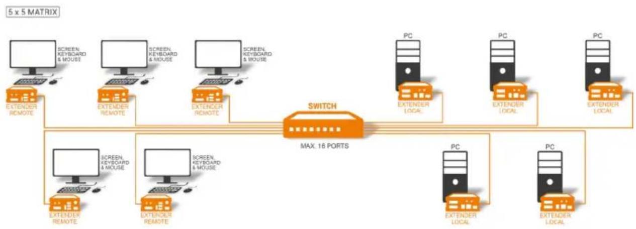
The units can be set up to access one host computer, or to access numerous host computers. In the case of the latter, an additional Network Switch must be installed. With a Network Switch, each user can gain quick access to any of the required computers.

flowchart
graph LR
    PC["PC"] --> EXTENDER_LOCAL["EXTENDER LOCAL"]
    EXTENDER_LOCAL -->|DISTANCE UP TO 100M / 160KM| EXTENDER_REMOTE["EXTENDER REMOTE"]
    EXTENDER_REMOTE -->|SCREEN| SCREEN["SCREEN"]
    SCREEN -->|KEYBOARD & MOUSE| EXTENDER_REMOTE
point to point connection
flowchart
graph TD
    A["5 x 5 MATRIX"] --> B["Switch"]
    B --> C["PC"]
    B --> D["PC"]
    B --> E["PC"]
    B --> F["PC"]
    B --> G["PC"]
    B --> H["PC"]
    B --> I["PC"]
    B --> J["PC"]
    B --> K["PC"]
    B --> L["PC"]
    B --> M["PC"]
    B --> N["PC"]
    B --> O["PC"]
    B --> P["PC"]
    B --> Q["PC"]
    B --> R["PC"]
    B --> S["PC"]
    B --> T["PC"]
    B --> U["PC"]
    B --> V["PC"]
    B --> W["PC"]
    B --> X["PC"]
    B --> Y["PC"]
    B --> Z["PC"]
    B --> AA["PC"]
    B --> AB["PC"]
    B --> AC["PC"]
    B --> AD["PC"]
    B --> AE["PC"]
    B --> AF["PC"]
    B --> AG["PC"]
    B --> AH["PC"]
    B --> AI["PC"]
    B --> AJ["PC"]
    B --> AK["PC"]
    B --> AL["PC"]
    B --> AM["PC"]
    B --> AN["PC"]
    B --> AO["PC"]
    B --> AP["PC"]
    B --> AQ["PC"]
    B --> AR["PC"]
    B --> AS["PC"]
    B --> AT["PC"]
    B --> AU["PC"]
    B --> AV["PC"]
    B --> AW["PC"]
    B --> AX["PC"]
    B --> AY["PC"]
    B --> AZ["PC"]
    B --> BA["PC"]
    B --> BB["PC"]
    B --> BC["PC"]
    B --> BD["PC"]
    B --> BE["PC"]
    B --> BF["PC"]
    B --> BG["PC"]
    B --> BH["PC"]
    B --> BI["PC"]
    B --> BJ["PC"]
    B --> BK["PC"]
    B --> BL["PC"]
    B --> BM["PC"]
    B --> BN["PC"]
    B --> BO["PC"]
    B --> BP["PC"]
    B --> BQ["PC"]
    B --> BR["PC"]
    B --> BS["PC"]
    B --> BT["PC"]
    B --> BU["PC"]
    B --> BV["PC"]
    B --> BW["PC"]
    B --> BX["PC"]
    B --> BY["PC"]
    B --> BZ["PC"]
    B --> CA["PC"]
    B --> CB["PC"]
    B --> CC["PC"]
    B --> CD["PC"]
    B --> CE["PC"]
    B --> CF["PC"]
    B --> CG["PC"]
    B --> CH["PC"]
    B --> CI["PC"]
    B --> CJ["PC"]
    B --> CK["PC"]
    B --> CL["PC"]
    B --> CM["PC"]
    B --> CN["PC"]
    B --> CO["PC"]
    B --> CP["PC"]
    B --> CQ["PC"]
    B --> CR["PC"]
    B --> CS["PC"]
    B --> CT["PC"]
    B --> CU["PC"]
    B --> CV["PC"]
    B --> CW["PC"]
Set up for Switching Systgem up to 48 endpoints
2. INSTALLATION OF THE EXTENDER
flowchart
graph TD
    A["PC"] -->|4. DVI in from PC| B["dvi-in"]
    B -->|1. Power plug 12V 1A| C["kvm-tec masterline"]
    C -->|4. DVI out to Monitor| D["SCREEN"]
    C -->|5. Audio from PC| E["local / pc"]
    E -->|6. Audio to PC| F["kvm-link"]
    F -->|3. Network cable CAT5e/6/7 up to 150m/492ft| G["kvm-tec masterline"]
    G -->|4. DVI out to Monitor| H["SCREEN"]
    G -->|5. Audio to Speaker| I["screen"]
    G -->|6. Audio from Microphone| J["controller"]
    J -->|2. USB from Keyboard and mouse| K["USB"]
    K -->|1. Power plug 12V 1A| L["kvm-link"]
2. INSTALLATION OF THE EXTENDER
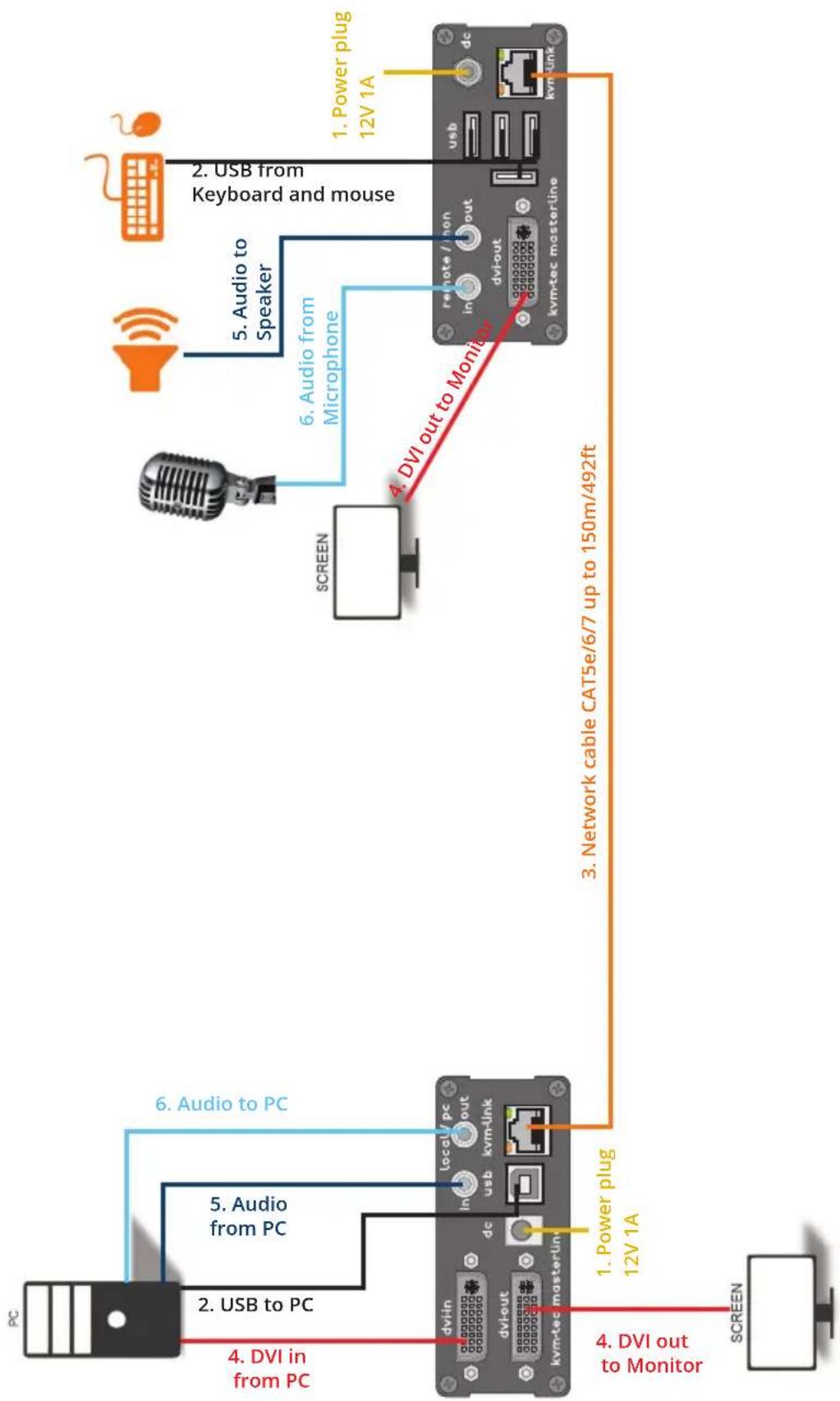
Quick Installation MVX1 Masterline local / CPU - remote/ CON
- Connect the CON / Remote and the CPU / Local Unit to the included 12V 1A power supply.
- Now connect the USB cable to a USB port on your PC and connect the other end of the USB cable to the CPU / Local Unit. Connect keyboard and mouse to the CON / Remote Unit.
- Connect the CPU / Local and the CON / Remote Unit with a network cable.
- Now connect the DVI cable to the DVI socket of the PC and the other end to the DVI socket of the CPU / Local Unit (DVI-in). Then connect the monitor to the CON / Remote Unit with a DVI cable.
- Then connect PC audio out with the audio cable to Local Audio in. Then connect audio / out via the audio cable
- Almost done! Now connect the audio cable Local Audio / out to the PC Audio in and Remote Audio / out with the audio cable to the microphone.
HAVE FUN - your kvm-tec Extender is now in use for many years ( MTBF approx 10 years)
2. INSTALLATION OF THE EXTENDER
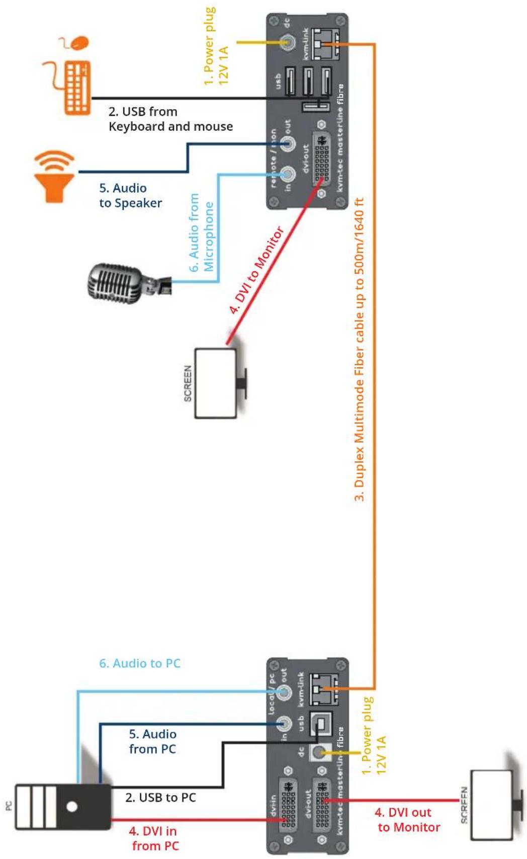
flowchart
graph TD
    A["PC"] -->|4. DVI in from PC| B["kvm-tec master/line fibre"]
    B -->|1. Power plug 12V 1A| C["kvm-tec master/line fibre"]
    C -->|3. Duplex Multimode Fiber cable up to 500m/1640 ft| D["kvm-tec master/line fibre"]
    D -->|4. DVI out to Monitor| E["SCREEN"]
    D -->|6. Audio to PC| F["kvm-link"]
    F -->|5. Audio from PC| G["dvi-out"]
    G -->|2. USB to PC| H["kvm-link"]
    H -->|6. Audio from Microphone| I["SCREEN"]
    I -->|4. DVI to Monitor| J["kvm-tec master/line fibre"]
    J -->|5. Audio to Speaker| K["dvi-out"]
    K -->|2. USB from Keyboard and mouse| L["kvm-link"]
    L -->|1. Power plug 12V 1A| M["kvm-link"]
2. INSTALLATION OF THE EXTENDER
Quick Installation MVX1-F FIBER MASTERLINE
local / CPU - remote/ CON
- Connect the CON / Remote and the CPU / Local Unit to the included 12V 1A power supply.
- Now connect the USB cable to a USB port on your PC and connect the other end of the USB cable to the CPU / Local Unit. Connect keyboard and mouse to the CON / Remote Unit.
- Connect the CPU / Local and the CON / Remote Unit with a fiber cable.
- Now connect the DVI cable to the DVI socket of the PC and the other end to the DVI socket of the CPU / Local Unit (DVI-in). Then connect the monitor to the CON / Remote Unit with a DVI cable.
- Then connect PC audio out with the audio cable to Local Audio in. Then connect audio / out via the audio cable
- Almost done! Now connect the audio cable Local Audio / out to the PC Audio in and Remote Audio / out with the audio cable to the microphone
HAVE FUN - your kvm-tec Extender is now in use for many years ( MTBF approx 10 years)
2. INSTALLATION OF THE EXTENDER
2.4 STARTUP
To start up the system without switch:
- Make sure that the two monitors and the computer are switched on.
- If you are using a Network Switch, connect the power supply to an earthed wall socket.
- Connect both extender power supplies (C) to an earthed wall socket. Both extenders will start an initialisation process. The red status LED blinks a few seconds. After a few seconds the status LED lights green. The monitor will displays your computer's desktop or any open applications.
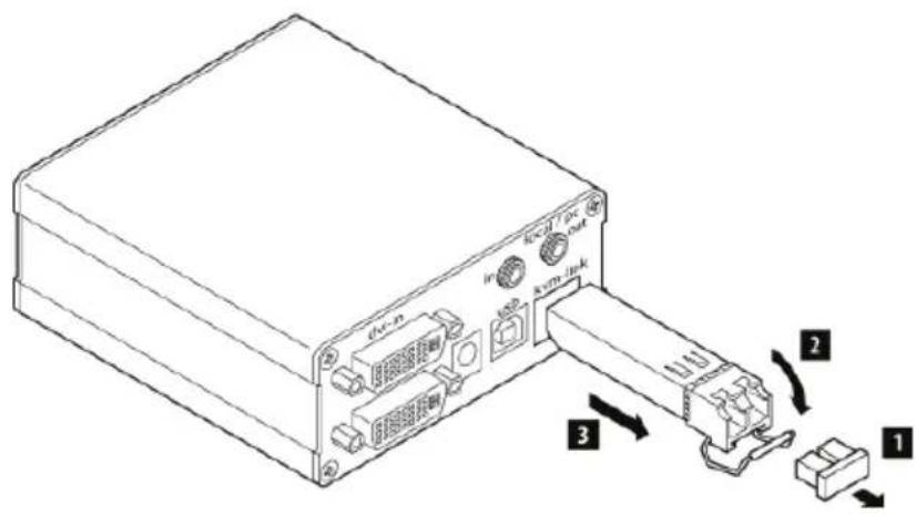
2.5 REPLACING THE SFP MODULE
The MVX1-F is delivered with a multimode SFP module.
To replace an SFP module with a different SFP module:
- Remove the black dust protector from the SFP module.
- Pull the metal latch of the SFP module forwards until it is at a right angle.
- Replace the SFP module with the other module. Put the metal latch back in position. Only use SFP modules from kvm-tec, or recommended by kvm-tec.
2. INSTALLATION OF THE EXTENDER
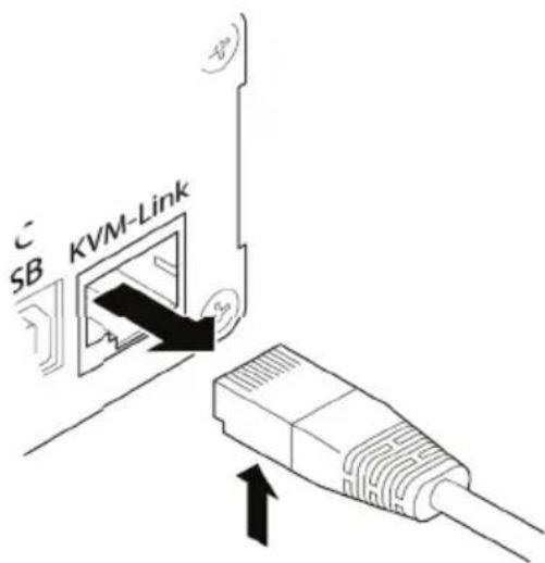
2.6 REMOVING A CATX CABLE
To remove a CATx cable:
- Press the latch down and slowly pull the cable out.
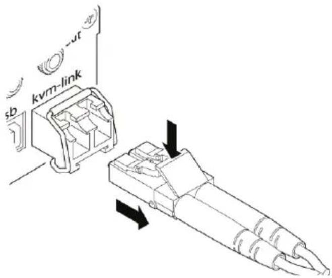
2.7 REMOVING A FIBER CABLE
To remove a fiber-cable:
- Press the latch down and slowly pull the cable out.
2. INSTALLATION OF THE EXTENDER
3.1 HOW TO ACCESS THE MAIN MENU
Use the monitor and keyboard to get access to the main menu.
To access the main menu:
- Make sure the extenders, the monitors and the computer are switched on.
- Press the Scroll Lock key on your keyboard quickly five times. The main menu appears with an overview of the sub-menus.
- To access a sub-menu press the applicable key.
KVM Home
T = Status Overview
U = Update Flash FW
M = Option Overview
O = DDC Option (Remote Monitor)
W = Network Settings
G = Extender Settings
L = Switching List
Q = Exit
Remote (Con) FW Ver = 4372
Local (PC) FW Ver = 4372
In the main menu, you can make the following settings by pressing the to select the corresponding letter.
T Status Overview Menu Status / Current Status:
U Update Flash FW Update firmware
M Option Overview Overview of all upgrades
O DDC Option DDC Option Fixed ice position 1020 x 1080
W Network Settings Network Settings
G ExtenderSettings Settings Extender
L Switching List List of all extenders in the switching system
Q Exit Exit
3. EXTENDER MENU/SETTINGS
3.2 STATUS MENU
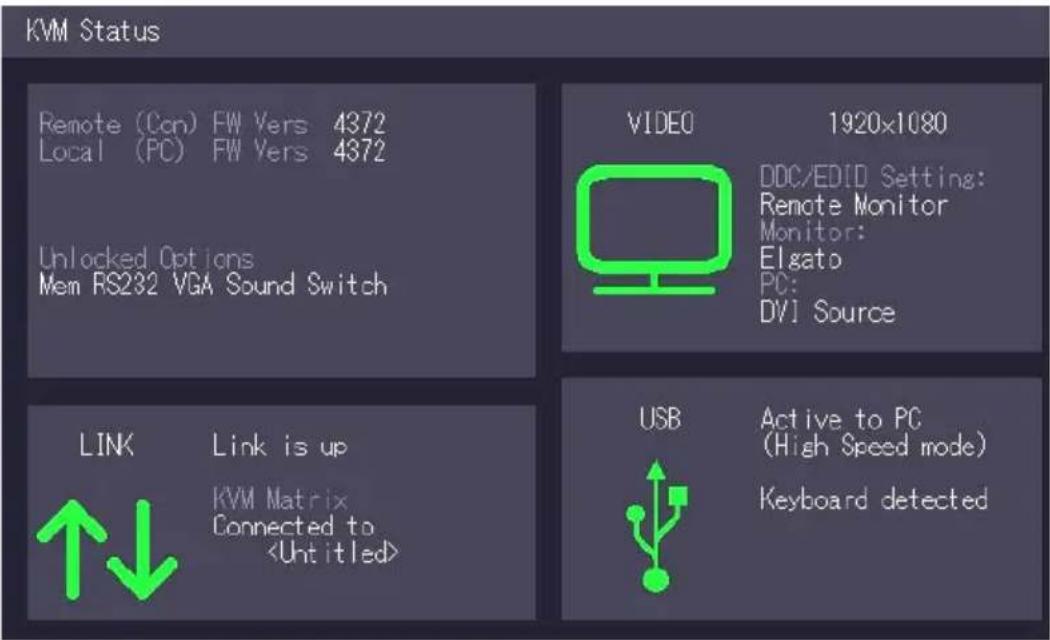
In the "Status Menu" the current status of the extender connection is displayed. It provides information on the connection itself as well as resolution of the video channel, and USB-status.
The enabled options and the current FW-version is displayed in the left top corner.
Link status shows whether there is a physical connection available. Connection indicates if kvm data is currently able to be transmitted.
Video and USB show if data is currently being transmitted.
3. EXTENDER MENU/SETTINGS
3.3 HOW DETERMINE THE CURRENT FIRMWARE VERSION
To view the firmware version:
- Make sure the main menu is open. The currently installed firmware versions of the remote and local units are displayed below (e.g. '4267')
KVM Home
T = Status Overview
U = Update Flash FW
M = Option Overview
O = DDC Option (Remote Monitor)
W = Network Settings
G = Extender Settings
L = Switching List
Q = Exit
Remote (Con) FW Ver = 4372
Local (PC) FW Ver = 4372
3. EXTENDER MENU/SETTINGS
3.4 HOW TO PERFORM A FIRMWARE UPDATE
The latest version of the firmware can be downloaded from http://www.kvm-tec.com/en/support/firmware-download.html. Each update file is accompanied by a detailed description of the update process.
There are four ways to perform an update:
- update via a bitmap image
- update from the USB stick
- automatic update
- network update
KVM Update

Basic Update:
U = Quick Update from Bitmap
S = Load Update from USB Stick (Do not plug in stick until prompted)

Advanced:
A = Automatic Update
N = Network Update

Remote unit. Firmware vers. 4372
Local unit. Firmware vers. 4372

Q Return to Main Menu
To perform a firmware update:
- Make sure the main menu is open.
- Press the U key. The Update menu appears.
- Press the N key to do a network update.
- Press the A key to do an automatic update.
- Press the U key to do a direct update.
- Press the S key to do a USB Update.
- Press the Q key to return to the main menu.
3. EXTENDER MENU/SETTINGS
3.4.1 UPDATE VIA A BITMAP IMAGE
The file will be output from an image and will be copied and stored to the currently connected extenders.
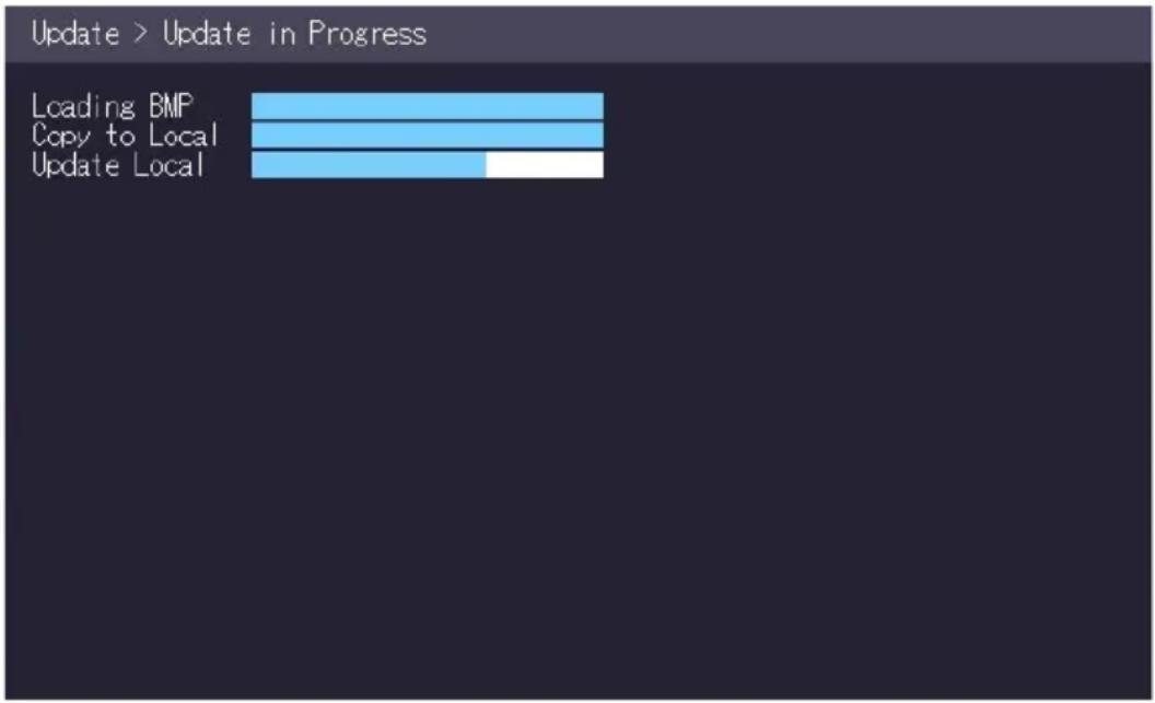
bar
| Category | Value | |---|---| | Loading BMP | 100 | | Copy to Local | 100 | | Update Local | 50 |Wait until all 3 phases of the update have been completed and make sure that you have Never unplug or plug in the devices during the update.
3. EXTENDER MENU/SETTINGS
3.4,2 UPDATE WITH USB STICK
For the update of the USb Stick the following steps are necessary:
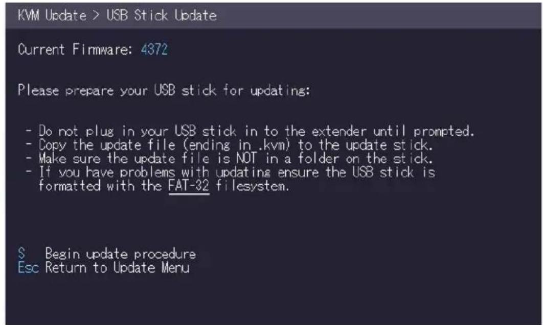
- you receive the message that you can plug in the USB stick.
- copy the update file (ending in .kvm) to the USB stick
- make sure that the update file is directly on the stick and that it is not in any subdirectory
- the USB stick must be formatted with FAT-32
3. EXTENDER MENU/SETTINGS
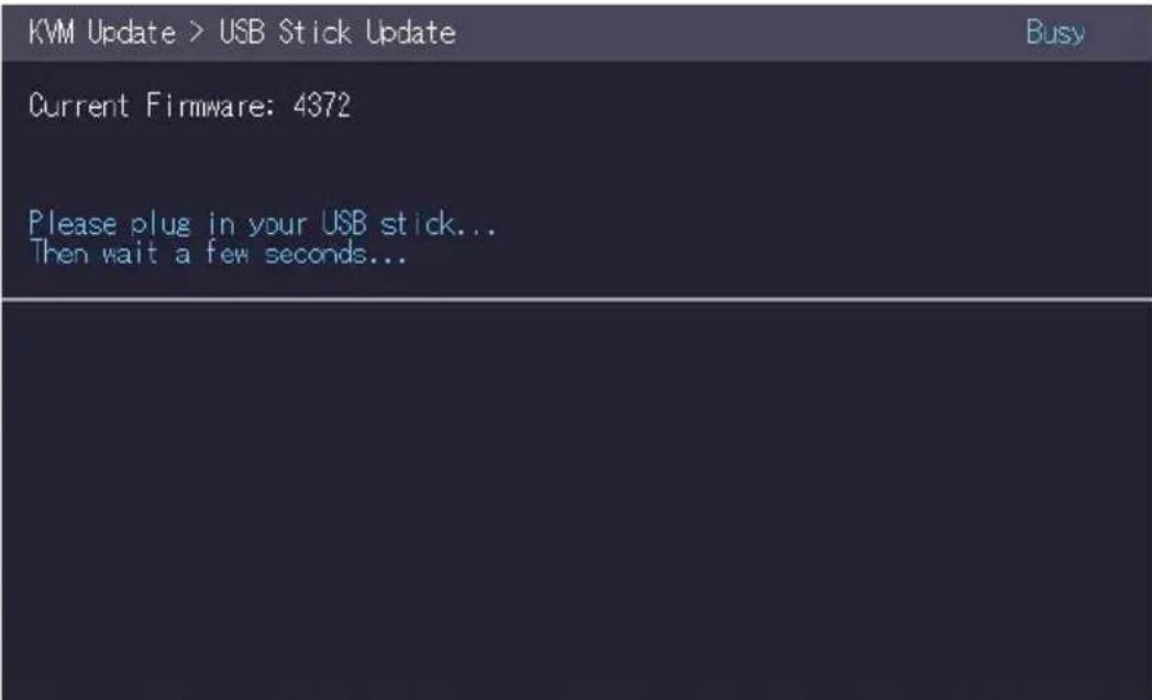
Plug in the USB stick and wait for a moment
3. EXTENDER MENU/SETTINGS
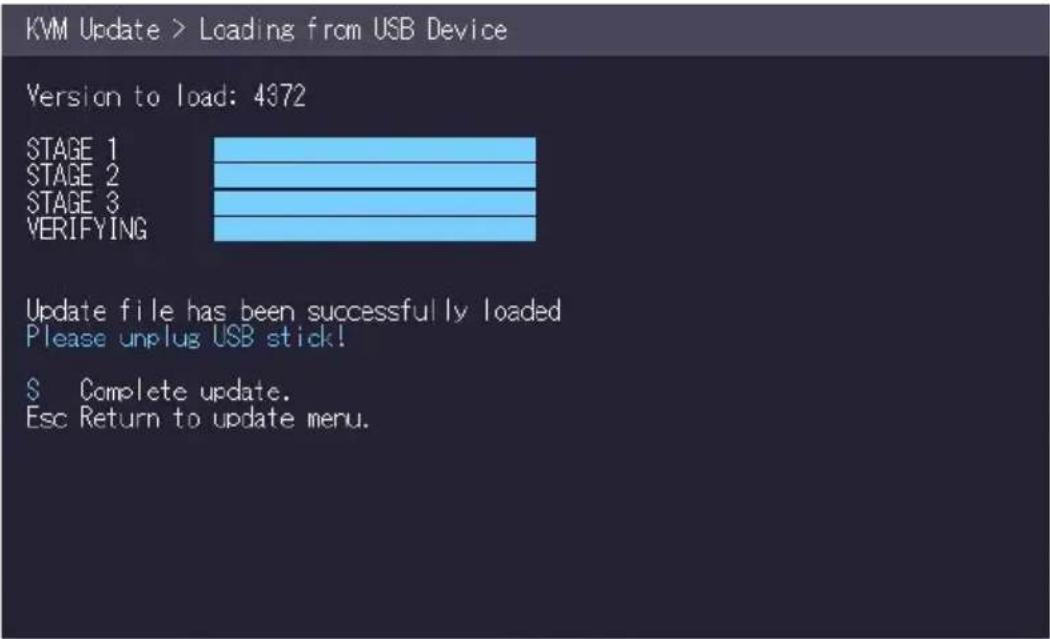
Wait until all 4 phases have been completed.
3. EXTENDER MENU/SETTINGS
3.4.3 PERFORMING AUTOUPDATE
You can select in the menu which part should be updated.
As soon as the devices are connected, the firmware is copied from one unit to the other.
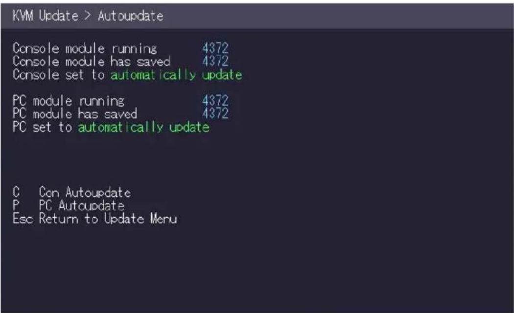
The flashing of the LEDs indicates that the update process has been completed (the LEDs are then green)
3. EXTENDER MENU/SETTINGS
3.4.4 PERFORMING NETWORK UPDATE
In the network update the devices that are updated can be marked.
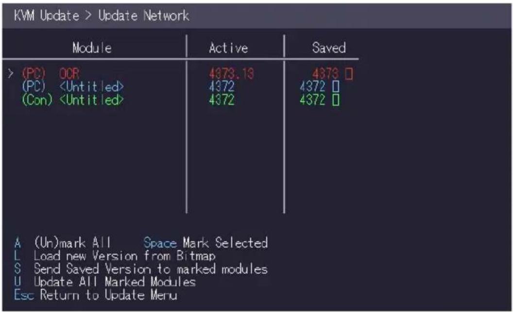
The information is then sent to the marked units. During this process the devices can still be in operation. As soon as all updates have been transmitted, the marked devices can be restarted and start with the new firmware.
3. EXTENDER MENU/SETTINGS
3.5 UNLOCK AN UPGRADE
- Make sure that the main menu is open. 2.
- press the M button. The Options Overview menu opens. The device ID will be order the unlock code from your supplier
- order the activation code from your supplier by entering the 9-digit device ID and enter the serial number of the KVM Extender. 4.
- press the M key to enter the unlock code.
- enter the unlock code of the supplier.
- the Extender will automatically restart.
To confirm that the option has been unlocked, return to the Options menu.
Overview and make sure that the corresponding option is now green.
![[USB Memory] - Enabled (1 - enable, 0 - disable) [RS232] [YGA] [Sound] [Switching] Device ID: 6c0783d95 Send ID to distributor to unlock options. Press M to enter code.](/content/2026/05/820773/images/e750e702f989e4c53b893c51c8caada4c55b8e17f43a50ec1efdcba3dda88741.jpg)
The information is then sent to the marked units. During this process the devices can still be in operation. As soon as all updates have been transmitted, the marked devices can be restarted and start with the new firmware.
3. EXTENDER MENU/SETTINGS
3.6 HOW TO ENABLE OR DISABLE THE USB MEMORY UPGRADE
The USB Memory Upgrade allows the user to enable or disable the memory upgrade. When the USB Memory upgrade is enabled, USB flash storage and external storage devices can be accessed via the extender. If your extender was provided with the USB Memory upgrade you can enable and disable at any time.
To enable or disable the USB Memory upgrade:
- Make sure the main menu is open.
- Press the M key. The Options Overview menu opens. The current USB Memory status is displayed (Enabled or Disabled).
- Press 1 to enable or 0 to disable the USB Memory upgrade
![[USB Memory] - Enabled (1 - enable, 0 - disable) [RS232] [VGA] [Sound] [Switching] Device ID: 6c0783d95 Send ID to distributor to unlock options. Press M to enter code.](/content/2026/05/820773/images/5fcecdf5162522425ce5bc5c5b6cb24a509c6653ab7f28fcdebee267f5b0043c.jpg)
The kvm-tec feature „USB save“ prevents the intrusion of viruses via the USB interface. by deactivating mass storage devices.
3. EXTENDER MENU/SETTINGS
3.7 HOW TO DEFINE WHAT DDC INFORMATION IS USED BY THE PC
The DDC Option menu allows the user to define what DDC information is used by the PC.
To define what DDC information is used by the PC:
- Make sure the main menu is open.
-
Press the O key. The DDC Option menu appears.
-
Press 0 to use the DDC information from the monitor attached to the remote extender.
- Press 2 to save the current DDC information. The system uses the same settings after the extender has been restarted.
-
Press 4 through 8 to use a predefined resolution which is saved.
-
Press ESC to go back to the main menu.
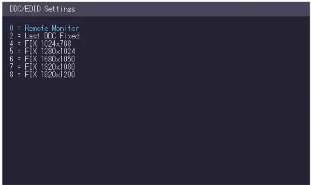
3.8 HOW TO CHANGE THE NETWORK SETTINGS
See chapter „Switching Menu Settings“.
3. EXTENDER MENU/SETTINGS
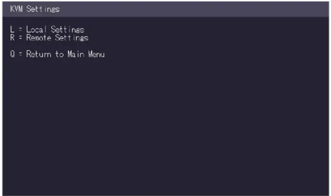
3.9 HOW TO CHANGE THE EXTENDER SETTINGS
The Extender Settings menu allows the user to change a range of further preferences. Three of the selections (VGA, Audio and RS232) will take you to sub-menus. The other four can be enabled or disabled by pressing the applicable key.
To access the Extender Settings menu:
- Make sure the main menu is open.
- Press the G key. The Extender Settings menu appears.
- The extender settings are distributed across two sub-menus: Remote Settings and Local Settings.
3. EXTENDER MENU/SETTINGS
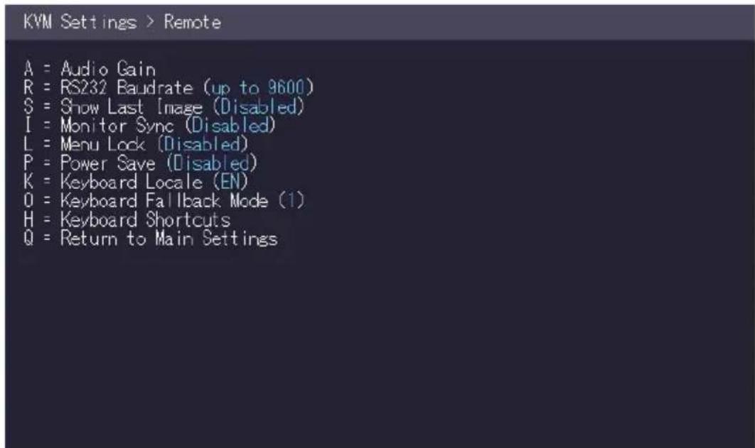
- To access the local or remote extender settings:
- Press the L key to access the Local Settings menu.
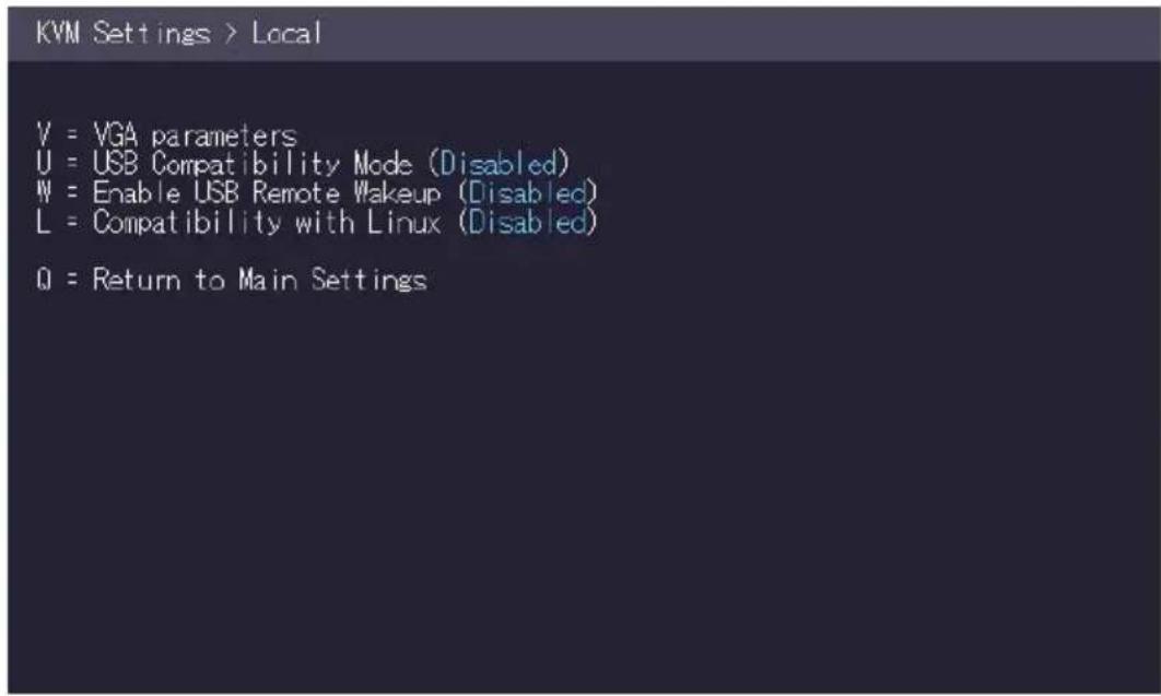
- Press the R key to access the Remote Settings menu.
3. EXTENDER MENU/SETTINGS
3.9.1 HOW TO OPTIMIZE VGA PREFERENCES
The VGA preferences can be set and optimized. The VGA option does only function when it has been unlocked (see 3.4).
To optimize the VGA settings:
- From the Extender Settings menu, press the L key. The Local Settings menu appears.
-
Press the V key. The VGA menu appears.
-
Press F1 to move the display area up.
- Press F4 to move the display area down.
- Press F2 to move the display area to the left.
- Press F3 to move the display area to the right.
- Press F5 to zoom out.
- Press F6 to zoom in.
- Press space to change the rate of the above mentioned setting. This toggles the rate of change between 1 and 10.
- Press M to switch the video mode between:
-
Auto – the mode is automatically detected and set by the extender.
• DVI – only DVI input is detected.
• VGA – only VGA input is detected. -
Press K for automatic adjustment and positioning of the image area.
- Press I to reset parameters to default values.
- Press S to save the settings and exit the menu.
- Press Q to exit without saving.
![Settings > VGA Parameters Shift up F1 F4 down D Shift <- F2 F3 -> D Zoom out F5 F6 in 2200 Pixelfine - F7 F8 + 21 Pixel Freq 148520 kHz Space = [Increment Size [I]/[10] M = Video Mode [DVI] A = Automatically Seek [Enabled] K = Seek Now I = Reset to Defaults S = Exit - Save Q = Quit - No Save](/content/2026/05/820773/images/8a2a9ccb724abc74c9e0ed358ff781685c38650aae917c02cbb977d62f7739b5.jpg)
3. EXTENDER MENU/SETTINGS
3.9.2 HOW TO ENABLE OR DISABLE THE USB COMPATIBILITY MODE
The USB compatibility mode can be enables or disabled.
To enable/disable the USB compatibility mode:
- From the Extender Settings menu, press the L key. The Local Settings menu appears.
- Press the U key to enable or disable the USB compatibility mode.

3. EXTENDER MENU/SETTINGS
3.9.3 HOW TO SET THE AUDIO VOLUME
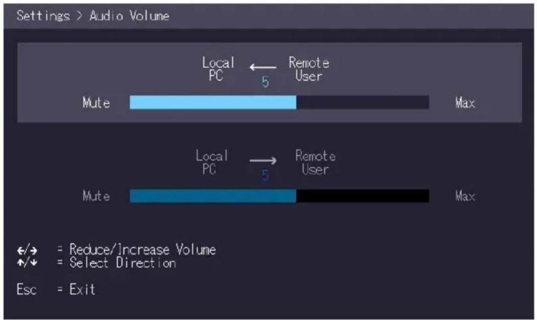
The volume of the audio input (microphone) on the remote unit can be changed. The default value is 5 but can be set to any value in between 0 and 9. At 0 the audio input on the remote unit is disabled.
To set the volume:
- From the Extender Settings menu, press the R key. The Remote Settings menu appears.
- Press the A key. The Audio Input Gain menu appears.
Press arrow left / right to change volume
Press arrow up / down to set directio
3.9.4 HOW TO SET THE BAUD RATE
FOR THE RS232
(SERIAL) CONNECTION
3. EXTENDER MENU/SETTINGS
Local Unit Pinout (DCE):
| Pin | Function | Direction |
| 2 | TxD | OUT |
| 3 | RxD | IN |
| 4 | DTR | IN |
| 5 | GND — | |
| 8 | CTS | OUT |
Remote Unit Pinout (DTE):
| Pin | Function | Direction |
| 2 | RxD | IN |
| 3 | TxD | OUT |
| 4 | DTR | OUT |
| 5 | GND — | |
| 8 | CTS | IN |
The pin numbers refer to a 9-pin D-sub plug.
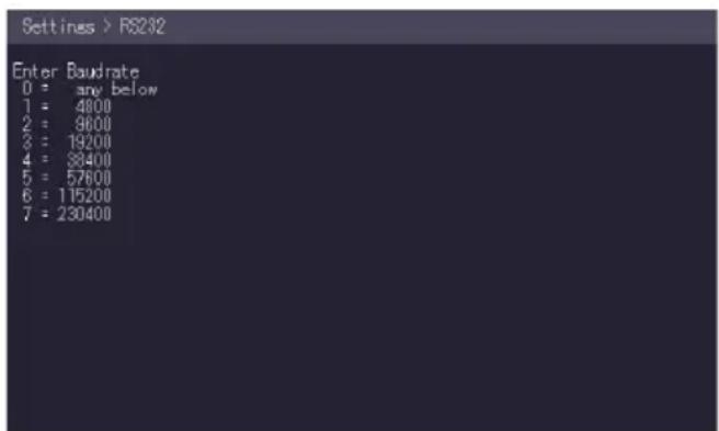
The baud rate can be set in the menu. There is a universal setting for baud rates up to 9600 which transmits all different RS232 configurations transparently. For higher baud rates the following settings are available via the menu:
Baudrate
| 4800 | No 1 |
| 9600 | Odd 2 |
| 19200 | Even |
| 38400 | Mark |
| 57600 | Space |
| 115200 | |
| 230400 |
Parity
Stopbits
To set the baud rate:
- From the Extender Settings menu, press the R key. The Remote Settings menu appears.
- Press the R key. The Baud Rate menu appears.
- To select a baud rate press the applicable key. The Enter Parity menu opens.
- To select a parity rate press the applicable key.
3. EXTENDER MENU/SETTINGS
3.9.5 HOW TO SHOW THE LAST RECEIVED IMAGE
With the function „show the last image“ the last received image can be used instead of a black screen, if the remote Extender (CON) is not being used by the local Extender (CPU) are separated. To show that this is the last received picture the frame of the image flashes red.
Activate or deactivate the „Show last Image“ function. 1:
- In the Extender Settings menu, press the R button. The Remote Settings menu becomes Press S to activate or deactivate the function.
- press S to activate or deactivate the function.
- press ESC to return to the main menu.
KVM Settings > Remote
A = Audio Gain
R = RS232 Baudrate (up to 9600)
S = Show Last Image (Enabled)
I = Monitor Sync (Disabled)
L = Menu Lock (Disabled)
P = Power Save (Disabled)
K = Keyboard Locale (EN)
D = Keyboard Fallback Mode (1)
H = Keyboard Shortcuts
Q = Return to Main Settings
3. EXTENDER MENU/SETTINGS
3.9.6 HOW TO TURN ON OR OFF MONITOR SYNCHRONIZATION
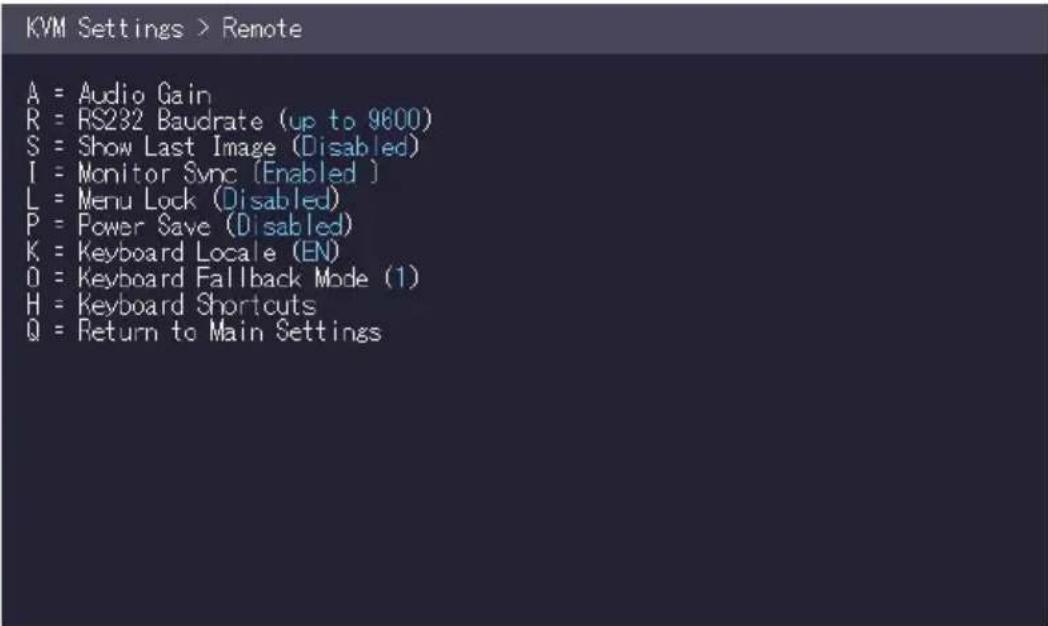
The monitor synchronization can be turned on and off. When enabled, the refresh rate of the graphics card of the PC and that of the remote monitor are adjusted to match one another. The advantage of this is to ensure that transmission remains smooth when the screen content changes rapidly (e.g. When using multimedia applications). Not all monitors support this method so by default this option is disabled.
To turn on monitor synchronization:
- From the Extender Settings menu, press the R key. The Remote Settings menu appears.
- Press the I key to enable or disable the function.
- Press ESC to go back to the main menu.
3. EXTENDER MENU/SETTINGS
3.9.7 HOW TO LOCK THE MAIN MENU
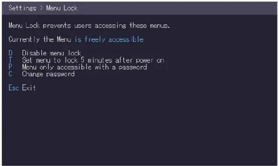
The extender menu can be locked. When enabled, the extender locks 5 minutes after start up to prevent unauthorized access.
To lock or unlock the menu:
- From the Extender Settings menu, press the R key. The Remote Settings menu appears.
- Press the L key. The Menu Lock Menu appears.
3. EXTENDER MENU/SETTINGS
3.9.8HOW TO USE POWER SAVING MODE
The power saving mode lets the extender turn off its video out when the remote extender does not receive a video signal for more than a minute.
To turn on or off the power saving mode:
- From the Extender Settings menu, press the R key. The Remote Settings menu appears.
- Press the P key to enable or disable the power saving mode.
- When in power saving mode, press any key to return to the menu.
KVM Settings > Remote
A = Audio Gain
R = RS232 Baudrate (up to 9600)
S = Show Last Image (Disabled)
I = Monitor Sync (Disabled)
L = Menu Lock (Disabled)
P = Power Save (Enabled)
K = Keyboard Locale (EN)
O = Keyboard Fallback Mode (1)
H = Keyboard Shortcuts
Q = Return to Main Settings
3. EXTENDER MENU/SETTINGS
3.9.9 HOW TO SELECT YOUR TYPE OF KEYBOARD
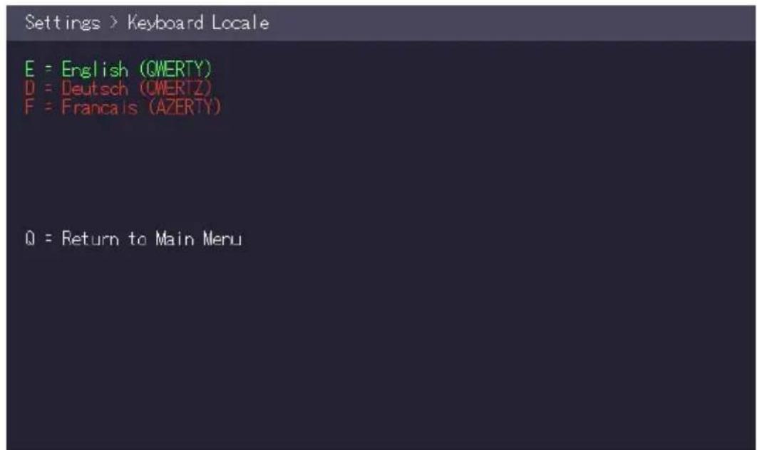
The Keyboard Locale menu lets you switch between keyboard layouts for navigating the on screen display menu (OSD). You can choose between French (Azerty), English (Qwerty) and German (Qwertz).
To select a keyboard layout:
- From the Extender Settings menu, press the R key. The Remote Settings menu appears.
-
Press the K key. The Keyboard Locale menu opens:
-
Press E to select English (QWERTY)
- Press D to select German (QWERTZ)
- Press F to select French (AZERTY)
3. EXTENDER MENU/SETTINGS
3.9.10 HOW TO CHANGE THE KEYBOARD FALLBACK MODE
To change the keyboard fallback mode:
- From the Extender Settings menu, press the R key. The Remote Settings menu appears.
- Press the O key to change the keyboard fallback mode to 0, 1 or 2.
KVM Settings > Remote
A = Audio Gain
R = RS232 Baudrate (up to 9600)
S = Show Last Image (Disabled)
I = Monitor Sync (Disabled)
L = Menu Lock (Disabled)
P = Power Save (Enabled)
K = Keyboard Locale (EN)
O = Keyboard Fallback Mode (2)
H = Keyboard Shortcuts
Q = Return to Main Settings
3. EXTENDER MENU/SETTINGS
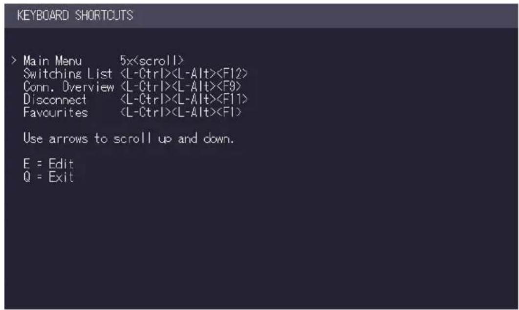
3.9.11 HOW TO CHANGE KEYBOARD SHORTCUTS
The Keyboard Shortcuts menu lets you edit the preferred shortcuts for common commands.
To edit the shortcuts:
- From the Extender Settings menu, press the R key. The Remote Settings menu appears.
- Press the H key. The Keyboard Shortcuts menu opens.
- Use the arrows to select a command.
- Press E to edit the shortcut.
To edit:
- Press a single key. Edit the frequency with left and right arrows.
- OR -
- Press a key combination
3.9.12 HOW TO CLOSE THE EXTENDER SETTINGS MENU
To close the Extender Settings menu:
- Press Q to close the Extender Settings menu.
3. EXTENDER MENU/SETTINGS
3.10 HOW TO SWITCH BETWEEN DIFFERENT COMPUTERS
The menu for switching between different computers is accessible via a USB keyboard connected to the remote unit.
-
Press Ctrl+Alt+F12 (this is the default keyboard shortcut but may be changed. See "How to change keyboard shortcuts"). The switching menu opens. The switching menu lists all the local units connected to the switching network.
-
Blue indicates the computer with which you are currently connected. The status is listed as "conn'd".
- White indicates a computer which is currently connected to by another work station (Remote unit). The status is listed as "in use".
- Green indicates a computer in the switching network that isn't connected to any work station (Remote unit). The status is listed as "free".
-
Red indicates a computer which was once in the switching network but isn't currently available. This usually indicates that the Extender has been disconnected from the network. If this is the case the computer can be removed from the switching menu with the "delete" key.
-
Use the arrow up and arrow down keys, or PGUP and PGDOWN keys, to select a local extender. Press enter. The system switches to the selected computer.
- The left column defines the favourites menu and provides each computer with a favourite number. Each favourite number corresponds to a hot-key combination that can be used to quickly connect to the desired computer without having to access the switching menu. For example favourite “1” has the hot-key combination
“Ctrl+Alt+F1” For favourite "2" this is “Ctrl+Alt+F2” and so on up to favourite "8" with “Ctrl+Alt+F8”. All other computers can still be accessed via the switching menu. To change the order of the computers in this list, select the computer then press a number key 1 through 8 to shift it to that number.
- If the password system is active, the user currently logged in is displayed at the bottom. You can manually logout by pressing the "x" key or disconnect from the current PC by pressing the „d" key.
3. EXTENDER MENU/SETTINGS
3.11 HOW TO SHARE VIDEOS
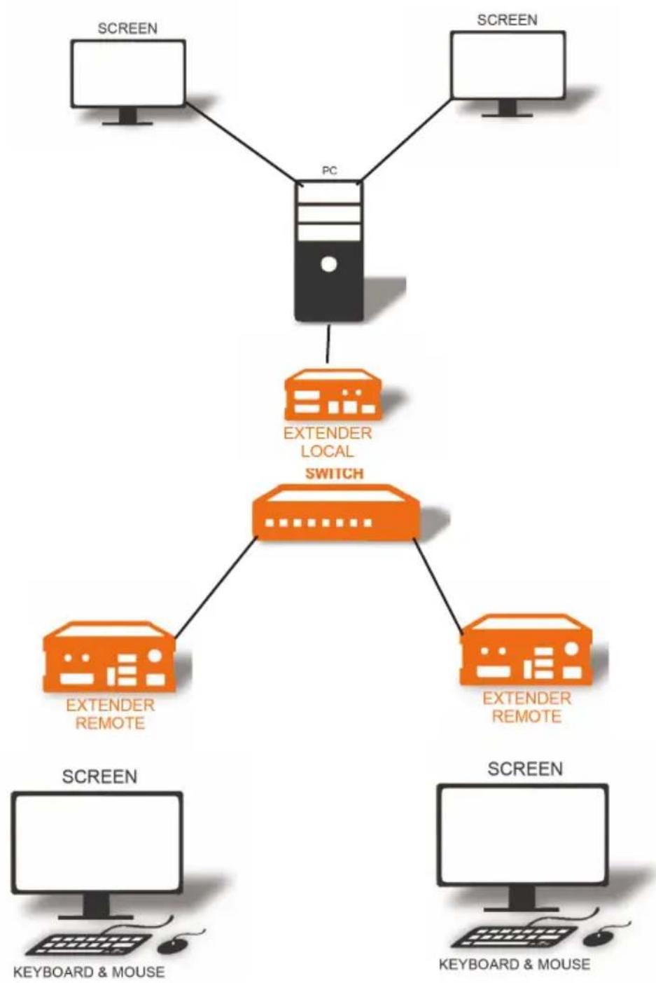
The Video Sharing option allows you to share your screen with other users on the network. Ensure that the switch you are using has IGMP Snooping capabilities, and that this is turned on (most switches have this off by default).
What happens with the control over the local extender depends on the initial state. There are two main use-cases which can both be controlled in the MASTER VIEW connections overview menu. Note that this capability is not available in combination with the password security system.
To share a video:
- Make sure the main menu is open.
- Press Ctrl+Alt+F10. The MASTER VIEW connections overview menu opens.
- Choose one of the following:
• To mirror a screen to other consoles:
- Press the P key on the keyboard of the extender that should display the user's screen. In this case „P“ stands for „push to screen“. Such a command is only valid if the console which initiates the mirroring is currently connected to a local unit and has video and the other remote unit is “free” (marked green).
• To see the screen of other consoles on the network:
- Press the G key on the keyboard of the extender that should display the user's screen. The key „G“ stands for „get screen“. If the console unit from which this command is executed currently has a partner, a disconnect is executed before the video of the other local unit is displayed. If the selected local extender currently isn't connected, a regular connection including USB, etc. is established.
3. EXTENDER MENU/SETTINGS
flowchart
graph TD
    A["PC"] --> B["EXTENDER LOCAL SWITCH"]
    B --> C["SCREEN"]
    B --> D["SCREEN"]
    B --> E["SCREEN"]
    B --> F["SCREEN"]
    B --> G["SCREEN"]
    B --> H["SCREEN"]
    B --> I["SCREEN"]
    B --> J["SCREEN"]
    B --> K["SCREEN"]
    B --> L["SCREEN"]
    style B fill:#f9f,stroke:#333,stroke-width:2px
Videosharing
4. NETWORK SETTINGS
4.1 HOW TO ACCESS THE NETWORK SETTINGS MENU (MASTER VIEW AND NETWORK MODE)
The Network Settings menu includes the preferences and settings for the Switching Option. Note: this menu is only available when the Switching Option has been unlocked (see chapter „How to unlock an Option“).
To access the Network Settings menu (Master View and Network Mode):
- Make sure the main menu is open (see chapter „How to access the main menu“)
- Press the W key. The Enter User/Password window opens.
NETWORK SETTINGS
V = Master View (Device Configuration)
M = Network Mode
T = Set Timeout ( Immediately )
Q = Save and Exit
4. NETWORK SETTINGS
- Log in with your user name and password. The Network Setting menu opens. Note: in order to prevent unauthorised access to the Network Settings, this option is protected by a user/password combination. Access is only allowed for users with administrator rights. The factory settings provide an administrator user with User: admin and Password: admin. The Master View option allows the administrator to view, add, edit or remove user, console and computer information.
Press the V key to access the Master View menu.
- The Network Mode allows to define how you want the network system to operate. Each of the modes available may individually be activated or deactivated by pressing the appropriate key. You may have more than one selected depending on their function. Some modes require others, and others are incompatible with each other, but the system will automatically recognise this for you. Press the M key to access the Network Mode menu.
MASTER VIEW
D = Connections Overview
U = User List
C = Console Extender List
P = PC Extender List
M = Multi-Head Configuration
R = Restart All Extenders
Q = Exit
4. NETWORK SETTINGS
4.2 HOW TO FORCE DISCONNECT OR SELECT A WORKSTATION FROM THE CURRENT CONNECTED DEVICES
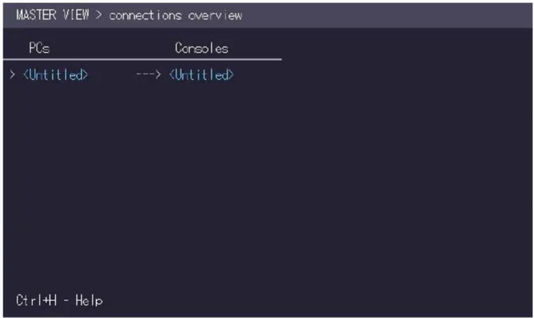
The Connection Overview provides an overview of the current connections as well as the free PCs and consoles on the network. You may break a connection remotely, or assign a PC a new console or vice versa.
To force disconnect or select a workstation from the current connected devices:
- Make sure the Master View menu is open (see chapter „How to access the Network Settings menu (Master View and Network Mode)“).
MASTER VIEW
Q = Connections Overview
U = User List
C = Console Extender List
P = PC Extender List
M = Multi-Head Configuration
R = Restart All Extenders
Q = Exit
4. NETWORK SETTINGS
- Press the O key. The Connection Overview menu opens.
-
Press the I key. The Connection Details window opens.
-
Press the D key to force disconnect the selected device/connection.
- Press the E key or Enter key to select a PC or workstation to create or break a ection to that unit.
- Press the Q key to exit.
4. NETWORK SETTINGS
4.3 HOW TO MANAGE USER DETAILS, RIGHTS AND GROUPS
The Console Extender List allows you to manage user details, rights and groups.
To manage user details, rights and groups:
-
Make sure the Master View menu is open (see chapter „How to access the Network Settings menu (Master View and Network Mode)“).
-
Press ⬆ to exit the menu.
MASTER VIEW
Q = Connections Overview
U = User List
C = Console Extender List
P = PC Extender List
M = Multi-Head Configuration
R = Restart All Extenders
Q = Exit
4. NETWORK SETTINGS
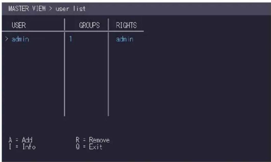
- Press the U key. The User List menu opens.
- Press the A key to add a new user.
- Press the R key to delete the selected user.
- Press the I key to display details about the selected user which may be edited.
4. NETWORK SETTINGS
Management User Details
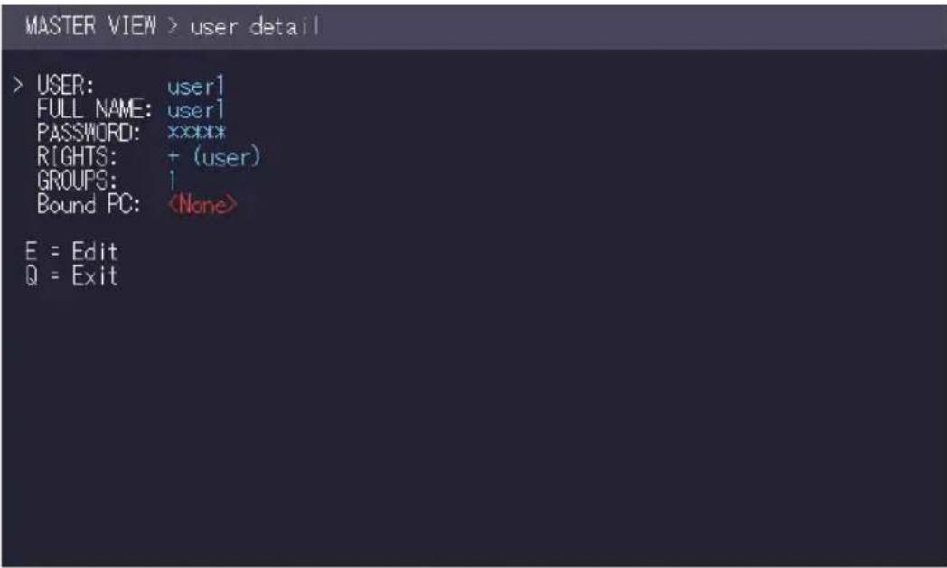
- To edit a user, press the I key. The User Detail menu opens.
- Select the user detail you want to edit and press the E key.
- User: Assign each user a login name with max. 12 characters.
• Full Name: For clarity the full name of a user may be entered with max. 20 characters. This name is displayed when informing other users who interrupted their connection.
- Password: Each user requires a password for the login. Max. 16 characters.
- Rights: There are three types of rights: USER, MASTER and ADMIN.
By pressing the + key the rights of the selected user can be changed. The rights control access to the Network Settings menu (only ADMIN), and which users may interrupt the connection of which other users.
- Admin: May interrupt connections of Masters and Users. In the case that an Admin interrupts the connection of another Admin, the interrupted Admin may reclaim the original connection. Private connections can't be interrupted.
- Master: May interrupt connections of Users. In the case that a Master interrupts the connection of another Master, the interrupted Master may reclaim the original connection. Admins and private connections can't be interrupted.
- User: In the case that a User interrupts the connection of another User, the interrupted User may reclaim the original connection. Admins, Masters and private connections can't be interrupted.
- Groups: Each user can join up to 8 user groups. Each computer is defined as belonging to one user group. By default all computers are in the same user group.
4. NETWORK SETTINGS
This system makes it possible to allow or deny different users access to a computer. The user's group access is set by pressing the buttons 1 - 8.
- Bound PC: When in User-PC Binding mode (see 4.10) each user must have a PC bound to them. That user will only be able to connect to that PC. When selected the User Detail menu, press RETURN a list of PCs on the network will be displayed to select from.
4.4 HOW TO VIEW THE STATUS OF ALL REMOTE UNITS
The Console Extender List allows you to view all remote units in the switching network and their current status.
To view the status of all remote extenders:
- Make sure the Master View menu is open (see chapter „How to access the Network Settings menu (Master View and Network Mode)“).
MASTER VIEW
O = Connections Overview
U = User List
C = Console Extender List
P = PC Extender List
M = Multi-Head Configuration
R = Restart All Extenders
Q = Exit
4. NETWORK SETTINGS
-
Press the C key. The Console Extender List menu opens.
-
"this" defines the extender which you are currently using.
- "in use" indicates that the extender is in use.
-
"free" indicates that this extender is not busy.
-
To edit the name of an extender, press the I key. The Console Extender Detail menu opens.
-
Press the E key to edit the name of the extender.
| MASTER VIEW > console extender list | |
| NAME | STATUS |
| > <Untitled> | this |
| R = Remove (Disconnected Only) I = Info Q = Exit | |
4. NETWORK SETTINGS
4.5 HOW TO VIEW THE STATUS OF ALL LOCAL UNITS
The PC Extender List allows you to view all local units in the switching network and their current status.
To view the status of all local units:
- Make sure the Master View menu is open (see chapter „How to access the Network Settings menu (Master View and Network Mode)“).
MASTER VIEW
Q = Connections Overview
U = User List
C = Console Extender List
P = PC Extender List
M = Multi-Head Configuration
R = Restart All Extenders
Q = Exit
- Press the P key. The PC Extender List menu opens.
4. NETWORK SETTINGS
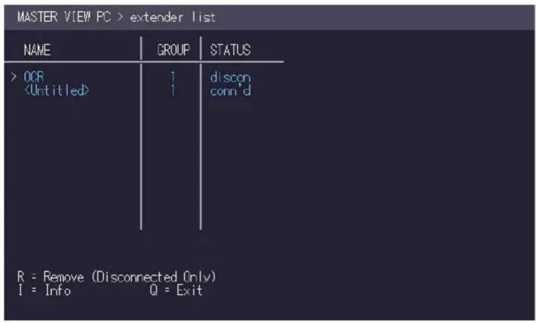
- To edit the name, groups or status of an extender, press the I key. The PC Extender Detail menu opens.
- Use the Up and Down Arrow keys to select the name or group of the PC unit.
- Press the E key to edit the selected parameter.
Example:
There are the following 3 PC's: Department PC, Team A PC and Team B PC. The users Alex, Blair and Charlie should have access to the Department PC and the Team A PC. The users Danny, Em and Frankie should have access to the Department PC and the Team B PC.
To achieve this we assign each PC a different group:
Department PC: Group 1
Team A PC: Group 2
Team B PC: Group 3
Alex, Blair and Charlie are assigned to be members of Group 1 and Group 2. Danny, Em and Frankie are assigned to be members of Group 1 and Group 3.
4. NETWORK SETTINGS
4.6 HOW TO SET UP DUAL-HEAD OR MULTI-HEAD SYSTEMS
If you use multiple monitors with a PC then you can group individual local and remote units together in the Multi-Head menu, making them switch as a single unit.
To group individual local and remote extenders:
- Make sure the Master View menu is open (see chapter „How to access the Network Settings menu (Master View and Network Mode)“).
MASTER VIEW
Q = Connections Overview
U = User List
C = Console Extender List
P = PC Extender List
M = Multi-Head Configuration
R = Restart All Extenders
Q = Exit
- Press the M key. The Multi-Head configuration menu opens.
4. NETWORK SETTINGS
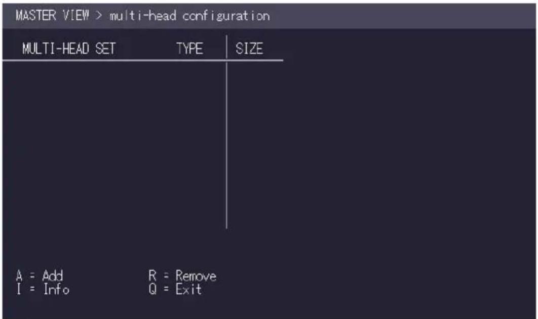
-
Press the A key. The multi-head detail menu opens.
-
Press the R key to remove an extender from the multi-head set.
- Press the Q key to exit.
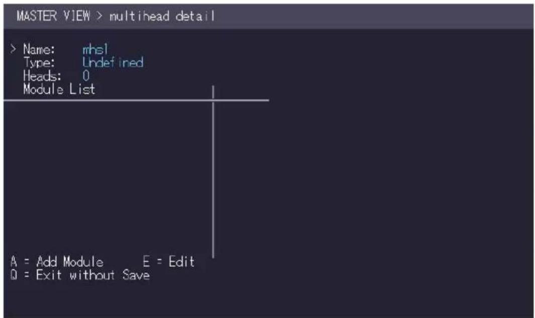
- Press the A key to add individual extenders. The extender type is automatically determined once the first extender has been selected.
- Press the E key to edit the multi-head set name of max. 16 characters.
4. NETWORK SETTINGS
4.7 HOW TO ENABLE USER GROUPS AND RIGHTS AND LOGIN ACCESS
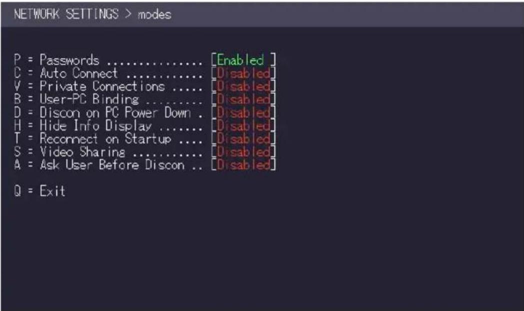
The Passwords option allows to activate user groups and rights and login access. For more information about user groups and rights see „How to manage user details, rights and groups“.
Access to the network settings is always protected by a login and password, even when the password system is disabled.
To enable the password option:
-
Make sure the Network Mode menu is open (see chapter „How to access the Network Settings menu (Master View and Network Mode)“).
-
Press the P key to disable or enable the option.
4. NETWORK SETTINGS
4.8 HOW TO AUTO-CONNECT TO A FREE COMPUTER AFTER AN INTERRUPTION
The Auto Connect option allows you to connect automatically with a free computer if your connection is interrupted by another user. This function is unavailable while using the Password System.
To enable the auto-connect option:
- Make sure the Network Mode menu is open (see chapter „How to access the switching menu Master View and Network Mode“).
- Press the C key to disable or enable the option.
NETWORK SETTINGS > modes
P = Passwords ....[Disabled]
C = Auto Connect ....[Enabled]
V = Private Connections ....[Disabled]
B = User-PC Binding ....[Disabled]
D = Discon on PC Power Down . [Disabled]
H = Hide Info Display ....[Disabled]
T = Reconnect on Startup ....[Enabled]
S = Video Sharing ....[Disabled]
A = Ask User Before Discon .. [Disabled]
Q = Exit
4. NETWORK SETTINGS
4.9 HOW TO SET UP A PRIVATE CONNECTION
The Auto Connect option allows you to set up a private connection with a computer, which can't be interrupted by other users.
To enable the private connection option:
- Make sure the Network Mode menu is open (see chapter „How to access the switching menu Master View and Network Mode“).
- Press the V key to disable or enable the option.
- To establish a private connection hold down Shift while you select a new connection (either in the switching menu or by pressing the hot-key combination (see chapter „How to switch between different computers“).
![NETWORK SETTINGS > modes P = Passwords ....... [Disabled] C = Auto Connect ....... [Disabled] V = Private Connections ....... [Enabled] B = User-PC Binding ....... [Disabled] D = Discon on PC Power Down . [Disabled] H = Hide Info Display ....... [Disabled] T = Reconnect on Startup ....... [Disabled] S = Video Sharing ....... [Disabled] A = Ask User Before Discon .. [Disabled] Q = Exit](/content/2026/05/820773/images/18214dbdcc98d5ca869f043ce17e302332e912aa8a084310e15a7060b9ce9168.jpg)
4. NETWORK SETTINGS
4.10 HOW TO ENABLE THE USER-PC BINDING MODE
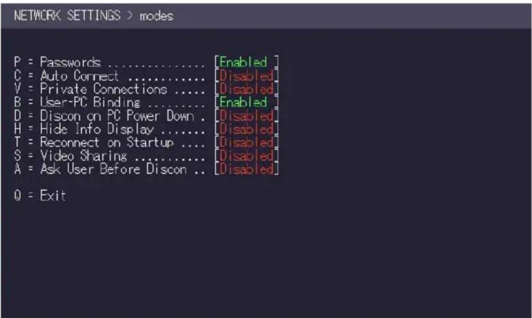
To enable the User-PC Binding mode:
-
Make sure the Network Mode menu is open (see chapter „How to access the switching menu Master View and Network Mode“).
-
Press the B key to disable or enable the option.
4. NETWORK SETTINGS
4.11 HOW TO ENABLE THE DISCONNECT ON PC POWER DOWN OPTION
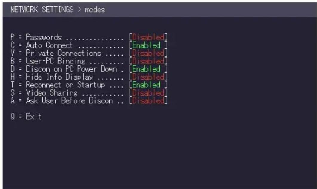
The Auto Connect option allows you to break the connection of any local unit that is connected to a PC that is powered down, allowing the remote unit to find a different local extender to connect to.
To enable the PC Power Down option:
-
Make sure the Network Mode menu is open (see chapter „How to access the switching menu Master View and Network Mode“).
-
Press the D key to disable or enable the option.
4. NETWORK SETTINGS
4.12 HOW TO HIDE INFO DISPLAY
To hide the info display during startup:
- Make sure the Network Mode menu is open (see chapter „How to access the switching menu Master View and Network Mode“).
- Press the H key to disable or enable the option.
![NETWORK SETTINGS > modes P = Passwords ....... [Disabled] C = Auto Connect ....... [Disabled] V = Private Connections ....... [Disabled] B = User-PC Binding ....... [Disabled] D = Discon on PC Power Down . [Disabled] H = Hide Info Display ....... [Enabled] T = Reconnect on Startup ....... [Disabled] S = Video Sharing ....... [Disabled] A = Ask User Before Discon .. [Disabled] Q = Exit](/content/2026/05/820773/images/a02e158884aa593d8f98b0c007d4cad484d15eb8726fbcf3c8fc470491d2eecb.jpg)
4. NETWORK SETTINGS
4.13 HOW TO RECONNECT ON STARTUP
To reconnect on startup:
-
Make sure the Network Mode menu is open (see chapter „How to access the switching menu Master View and Network Mode“).
-
Press the T key to disable or enable the option.
![NETWORK SETTINGS > modes P = Passwords ....... [Disabled] C = Auto Connect ....... [Disabled] V = Private Connections ....... [Disabled] B = User-PC Binding ....... [Disabled] D = Discon on PC Power Down . [Disabled] H = Hide Info Display ....... [Disabled] T = Reconnect on Startup ....... [Enabled] S = Video Sharing ....... [Disabled] A = Ask User Before Discon .. [Disabled] Q = Exit](/content/2026/05/820773/images/e6753b4c5bad85bb7705ef37fd9a8022175d6b03a91900739b5474c22fea9f1a.jpg)
4.14 VIDEO SHARING
See chapter „How to share videos“.
4. NETWORK SETTINGS
4.15 HOW TO SET THE PASSWORD TIMEOUT
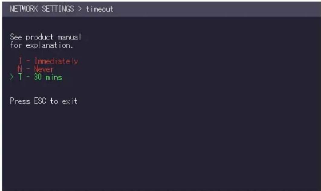
When the password system is activated you can define under what circumstances the user will be required to re-enter their login details when switching.
- I – Immediately: User and password must be re-entered for each switch.
- N – Never: User and password are not required to be re-entered until the current user logs out. See chapter „How to switch between different computers“.
- T - Time in min: You define the number of minutes since the last switch before the user and password details are required again to switch.
5. MAINTENANCE AND CARE
CAUTION! Do not use solvent-containing cleansers. Do not use wipes, alcohols (e.g. spiritus) or chemicals as these could damage the surface.
To clean the product:
- Clean the product with a maintenance product for synthetic material, which is available in specialized shops.
6. TROUBLESHOOTING
Error Cause Solution
| LED is not lighting | The devices get no power | Is the power supply connected? (white box) |
| LED is lighting in red | No connection between Loc and Rem | Check if the RJ45/network cable is connected well. (Clicking noise when plugging in)Control both, if it does not work please send an e-mail to support@kvm-tec.com |
| LED is lighting in orange | No picture on the monitor | Check if the local (PC) cable is connected well.Check if the remote (monitor) cable is connected well.If everything is connected well but no function appears, reconnect power supply again.If the menu is visible, press the O key and choose the resolution of the monitor. Then press the assigned number on your keyboard. |
| LED is lighting green | Screen occurs but the keyboard is not working | Plug out/in USB of keyboard and wait until driver is installed (after few seconds).Check all USB connections on both sides (Local and Remote)If it is still not working, plug out/in DC once more |
LED is lighting No audio Establish audio connection:
| green | plug stereo-jack to the audio output of the PC (green) connection with local: INremote: headset OUTEstablish microphone connection:plug stereo-jack to the microphone input of the PC (pink) connection with local OUT. Connect the microphone to the Remote IN |
6. TROUBLESHOOTING
| Error Cause Solution | ||
| LED is lighting green | The screen fl ickers, has an incorrect display | Install current fi rmware from our homepage www.kvm-tec.com/support |
| LED is blinking green | Different fi rmware or USB is not compatible | Please contact the kvm-tec support team via e-mail:support@kvm-tec.comor by phone: +43 2253 81912 30 |
| LED are lighting differently | Different fi rmware | To enter on screen menu/check fi rmware version:To enter the On screen menu, press the Scroll Lock key fi ve times in quick succession. The currently installed fi rmware version is displayed below the menuIf fi rmware update does not work, please send an e-mail tosupport@kvm-tec.com |
7. DISPOSAL

natural_image
Simple line drawing of a trash bin with crossed lines indicating no waste or plastic (no text or symbols)This symbol on the product, the accessories or packaging indicates that this product must not be treated as unsorted municipal waste, but must be collected separately! Dispose of the product via a collection point for the recycling of waste electrical and electronic equipment within the EU and in other European countries that operate separate collection systems for waste electrical and electronic equipment.
By disposing of the product in the proper manner, you help to avoid possible hazards for the environment and public health that could otherwise be caused by improper treatment of waste equipment. The recycling of materials contributes to the conservation of natural resources. Therefore do not dispose of your old electrical and electronic equipment with the unsorted municipal waste.
The packaging is made of environmentally friendly materials, which may be disposed through your local recycling facilities. By disposing of the packaging and packaging waste in the proper manner, you help to avoid possible hazards for the environment and public health.
8. WARRANTY
Warranty lasts 24 months from the date of purchase. The defect product has to be sent back to the manufacturer or your supplier within 2 weeks. The warranty becomes void in case of:
• External forceful impact
- Inappropriate maintenance
- Violating the operating instructions
- Damage by lightning
Always contact us first before sending back the product.
9. SUPPORT
If you have any questions about our products, please contact your dealer.
kvm-tec electronic gmbh
Email: support@kvm-tec.com
Web: www.kvm-tec.com
kvm-tec Inc. USA Sales p+1 213 631 3663 &
+43 225381912-22
email: officeusa@kvm-tec.com
kvm-tec ASIA-PACIFIC Sales p +9173573 20204
email: sales.apac@kvm-tec.com
kvm-tec China Sales - P + 86 1360 122 8145
email: chinasales@kvm-tec.com
kvm-tec Chinasales email chinasales @kvm-tec.com
Find our newest updates and FAQs on our homepage: http://www.kvm-tec.com/support
10. DECLARATION OF CONFORMITY
EU DECLARATION OF CONFORMITY
Manufacturer: KVM-TEC Electronic GmbH
Gewerbepark Mitterfeld 1A, 2523 Tattendorf, Austria
Commercial register number: FN 272328h LG Wr. Neustadt
I hereby declare that the device
fulfils following EU Directive and European standards listed within:
EMC/EMV - EU Directive 2014/30/EU and 2014/35/EU
2014/35/EU low voltage directive
2014/30/EU EMV directive
The device was tested in a typical application with a PC.
RoHS II - EU Directive 2011/65/EU
Certificate according to RoHS II Directive 2011/65 / EU
We hereby certify that all our products are manufactured and packaged in accordance with
RoHS II 2011/65/EU and PFOS 2006/122EG directives.
REACH - Regulation (EG) No. 1907/2006
For our products, we only use commercially available, well-known components from well-known manufacturers, which do not exceed the thresholds for Substances of Very High Concern (SVHC) and do not fall into the obligations for the production and placing on the market of substances / chemicals for pre-registration or registration (ECHA) fall.
10. DECLARATION OF CONFORMITY
Ecodesign Directive 2009/125/EC
In particular, the limits of the following standards are observed:
EN 55032:2012 Class A *
EN 55024:2010
EN 61000-3-2:2014
EN 61000-3-3:2013
EN 60950-1:2006+A2:2013, IEC 60950:2005
LASER CLASS 1: EN 60825-1:2007 compatible with IEEE 803.3z
Signed for and on behalf of: KVM-TEC Electronic GmbH
Place and date of issue: Tattendorf, 2018-05-09
A Cat5/6/7 cable should meet the following requirements:
- The pins are connected 1:1. Caution: the cable pairs must be twisted to EIA/TIA-568A (rare) or EIA/TIA-568 B (common) pairs.
- Erroneous assignments cannot be found with a simple cable tester.
- The pins for the green pair of wires are not adjacent to one other.
- The cable must at the very least meet the CAT5 specifications and be suitable for Gigabit transmission.
- The cable should meet one of the following standards: Class D ISO/IEC 11801:2002 or EN 50173-1:2002. Schema EIA/TIA-568 B.
- Only use shielded installation cable with min. cross section of 24 AWG throughout the length.
- The shield should be contiguous and connected to both ends. A shielded patch cable is allowed for connection to the device.
Schema EIA/TIA-568 B
| Pin Color |
| 1 Orange/White |
| 2 Orange |
| 3 Green/White |
| 4 Blue |
| 5 Blue/White |
| 6 Green |
| 7 Brown/White |
| 8 Brown |
11. REQUIREMENTS FOR CABLES
11.2 REQUIREMENTS FIBER CABLES
11.2.1 MULTI-MODE (STANDARD)
A Multi-Mode fibre cable should meet the following requirements:
- Maximum length should be 500 m. The MVX1-F includes a fibre Multimode – SFP Module which allows a transmission distance of up to 500 m.
• Dedicated fibre connection cable type Duplex Multimode 50/125 µ (OM2), LC connector
11.2.2 SINGLE-MODE (OPTIONAL)
A fibre Single-Mode – SFP Module cable should meet the following requirements:
- Up to 20 km transmission distance.
- Requires dedicated fibre connection: cable type Duplex Singlemode with LC connector
A fibre Single-Mode – SFP Module BiDi cable should meet the following requirements:
- Up to 20 km transmission distance.
- Requires dedicated fibre connection: cable type Singlemode with LC connector Wavelength (☐) of 850 nm in multi-mode or 1310 nm TX -1550 nm RX in single-mode
12. REQUIREMENTS NETWORK SWITCH
The entire switching network system requires its own dedicated network. For security reasons it cannot be integrated into an existing company network.
The network switch must fulfil the following specifications:
1 Gigabit Switch, with true port to port transfer rates of 1 Gigabit/second
The following switches have all been tested and verified to work with all features of kvm-tec electronic's SVX Smartline and MVX Masterline and MX Matrixline KVM-extenders.
12. REQUIREMENTS FOR NETWORK-SWITCH
Recommended Switches
SWITCH
natural_image
Orange rectangular object with white horizontal bars and four small square cutouts (no text or symbols)Multiple Switch
Single Switch
| Art Nr | Item Nr Product | |
| CATx SWITCHHE | ||
| 6514 | NS8RJ/2SFP Network Switch | 8x RJ45 1000 Base-T / 2x SFP 1G |
| 6534 | NS24RJ/4SFP Network Switch | 24x RJ45 1000 Base-T / 4x SFP 1G |
| 6141 | NS24RJ/2SFP/2SFP+ Network | Switch 24x RJ45 1000 Base-T / 2x SFP 1G / 2x SFP+ 10G |
| 6155 | NS48RJ/4SFP+ Network Switch | 48x RJ45 1000 Base-T / 4x SFP+ 10G |
| 6171 | NS48RJ+/2SFP+ Network Switch | 48x RJ45 10G / 2x SFP+ 10G |
| FIBER SWITCHHE | ||
| 6146 | NS24SFP/4SFP+ | Network Switch 24x SFP/4x SFP+ |
| 6166 | NS48SFP/4SFP+ Network Switch | 48 x SFP/4x SFP+ with redundancy power supply |
| 6151 | NS32SFP+/2QSFP+ | Network Switch 32 x SFP/2x QSFP+ |
| 6161 | NS48SFP+/4QSFP+ Network | Switch 48x SFP+ 10G / 4x QSFP+ |
13. FIRST AID
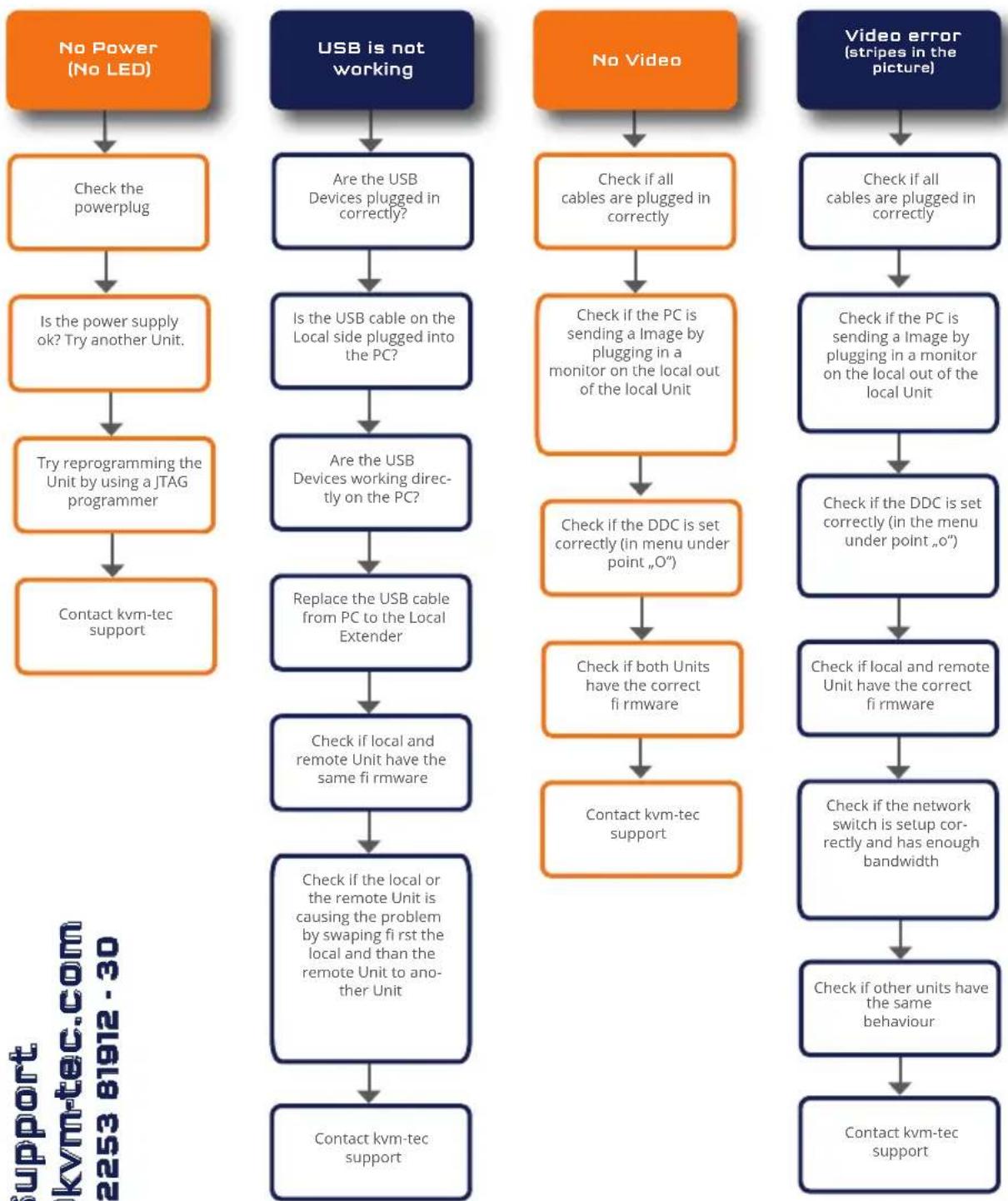
flowchart
graph TD
    A["No Power (No LED)"] --> B["Check the powerplug"]
    B --> C["Is the power supply ok? Try another Unit"]
    C --> D["Try reprogramming the Unit by using a JTAG programmer"]
    D --> E["Contact kvm-tec support"]

    F["USB is not working"] --> G["Are the USB Devices plugged in correctly?"]
    G --> H["Is the USB cable on the Local side plugged into the PC?"]
    H --> I["Are the USB Devices working directly on the PC?"]
    I --> J["Replace the USB cable from PC to the Local Extender"]
    J --> K["Check if local and remote Unit have the same fi rmware"]
    K --> L["Check if the local or the remote Unit is causing the problem by swapping fi rst the local and than the remote Unit to another Unit"]
    L --> M["Contact kvm-tec support"]

    N["No Video"] --> O["Check if all cables are plugged in correctly"]
    O --> P["Check if the PC is sending a Image by plugging in a monitor on the local out of the local Unit"]
    P --> Q["Check if the DDC is set correctly (in menu under point „O”)"]
    Q --> R["Check if both Units have the correct fi rmware"]
    R --> S["Contact kvm-tec support"]

    T["Video error (stripes in the picture)"] --> U["Check if all cables are plugged in correctly"]
    U --> V["Check if the PC is sending a Image by plugging in a monitor on the local out of the local Unit"]
    V --> W["Check if the DDC is set correctly (in the menu under point „o”)"]
    W --> X["Check if local and remote Unit have the correct fi rmware"]
    X --> Y["Check if the network switch is setup correctly and has enough bandwidth"]
    Y --> Z["Check if other units have the same behaviour"]
    Z --> AA["Contact kvm-tec support"]
kvm-tec Support
support@kvm-tec.com
Phone: +43 2253 81912 - 30
We are here for you to answer your questions about installation?
Manual download www.kvm-tec.com
or
kvm-tec Installationchannel on our homepage
personally +43 2253 81912

14. EXTENDED WARRANTY

2 years warranty

Part nr 9003 Warranty extension to 5 years per set
Part nr 9002 Warranty extension to 5 years per uni
15. NOTES


- TABLE OF CONTENTS
- Introduction 6
- Installation of the extender 13
- Extender menu/settings 23
- Network Settings 51
- INTRODUCTION
- INTENDED USE
- SAFETY INSTRUCTIONS
- WARNING! Read and understand all safety instructions.
- TECHNICAL SPECIFICATIONS
- PRODUCT ELEMENTS
- Nr. Name Function
- MEANING OF LED INDICATORS
- INSTALLATION OF THE EXTENDER
- UNPACKING AND CHECKING THE CONTENTS
- MOUNTING OPTIONS
- MOUNTING PADS AND RUBBER FEET
- To attach the mounting pads or rubber feet:
- MOUNTING KITS (OPTIONAL)
- The following mounting kits are available:
- INSTALLING THE EXTENDER
- Quick Installation MVX1 Masterline local / CPU - remote/ CON
- Quick Installation MVX1-F FIBER MASTERLINE
- STARTUP
- To start up the system without switch:
- REPLACING THE SFP MODULE
- To replace an SFP module with a different SFP module:
- REMOVING A CATX CABLE
- To remove a CATx cable:
- REMOVING A FIBER CABLE
- To remove a fiber-cable:
- HOW TO ACCESS THE MAIN MENU
- To access the main menu:
- EXTENDER MENU/SETTINGS
- STATUS MENU
- HOW DETERMINE THE CURRENT FIRMWARE VERSION
- To view the firmware version:
- HOW TO PERFORM A FIRMWARE UPDATE
- To perform a firmware update:
- UPDATE VIA A BITMAP IMAGE
- 3.4,2 UPDATE WITH USB STICK
- PERFORMING AUTOUPDATE
- PERFORMING NETWORK UPDATE
- UNLOCK AN UPGRADE
- HOW TO ENABLE OR DISABLE THE USB MEMORY UPGRADE
- To enable or disable the USB Memory upgrade:
- HOW TO DEFINE WHAT DDC INFORMATION IS USED BY THE PC
- To define what DDC information is used by the PC:
- HOW TO CHANGE THE NETWORK SETTINGS
- HOW TO CHANGE THE EXTENDER SETTINGS
- To access the Extender Settings menu:
- HOW TO OPTIMIZE VGA PREFERENCES
- To optimize the VGA settings:
- HOW TO ENABLE OR DISABLE THE USB COMPATIBILITY MODE
- To enable/disable the USB compatibility mode:
- HOW TO SET THE AUDIO VOLUME
- To set the volume:
- HOW TO SET THE BAUD RATE
- FOR THE RS232
- (SERIAL) CONNECTION
- To set the baud rate:
- HOW TO SHOW THE LAST RECEIVED IMAGE
- Activate or deactivate the „Show last Image“ function. 1:
- HOW TO TURN ON OR OFF MONITOR SYNCHRONIZATION
- To turn on monitor synchronization:
- HOW TO LOCK THE MAIN MENU
- To lock or unlock the menu:
- 3.9.8HOW TO USE POWER SAVING MODE
- To turn on or off the power saving mode:
- HOW TO SELECT YOUR TYPE OF KEYBOARD
- To select a keyboard layout:
- HOW TO CHANGE THE KEYBOARD FALLBACK MODE
- To change the keyboard fallback mode:
- HOW TO CHANGE KEYBOARD SHORTCUTS
- To edit the shortcuts:
- HOW TO CLOSE THE EXTENDER SETTINGS MENU
- HOW TO SWITCH BETWEEN DIFFERENT COMPUTERS
- HOW TO SHARE VIDEOS
- To share a video:
- NETWORK SETTINGS
- HOW TO ACCESS THE NETWORK SETTINGS MENU (MASTER VIEW AND NETWORK MODE)
- To access the Network Settings menu (Master View and Network Mode):
- HOW TO FORCE DISCONNECT OR SELECT A WORKSTATION FROM THE CURRENT CONNECTED DEVICES
- To force disconnect or select a workstation from the current connected devices:
- HOW TO MANAGE USER DETAILS, RIGHTS AND GROUPS
- To manage user details, rights and groups:
- Management User Details
- HOW TO VIEW THE STATUS OF ALL REMOTE UNITS
- To view the status of all remote extenders:
- HOW TO VIEW THE STATUS OF ALL LOCAL UNITS
- To view the status of all local units:
- Example:
- HOW TO SET UP DUAL-HEAD OR MULTI-HEAD SYSTEMS
- To group individual local and remote extenders:
- HOW TO ENABLE USER GROUPS AND RIGHTS AND LOGIN ACCESS
- To enable the password option:
- HOW TO AUTO-CONNECT TO A FREE COMPUTER AFTER AN INTERRUPTION
- To enable the auto-connect option:
- HOW TO SET UP A PRIVATE CONNECTION
- To enable the private connection option:
- HOW TO ENABLE THE USER-PC BINDING MODE
- To enable the User-PC Binding mode:
- HOW TO ENABLE THE DISCONNECT ON PC POWER DOWN OPTION
- To enable the PC Power Down option:
- HOW TO HIDE INFO DISPLAY
- To hide the info display during startup:
- HOW TO RECONNECT ON STARTUP
- To reconnect on startup:
- VIDEO SHARING
- HOW TO SET THE PASSWORD TIMEOUT
- MAINTENANCE AND CARE
- To clean the product:
- TROUBLESHOOTING
- DISPOSAL
- WARRANTY
- SUPPORT
- DECLARATION OF CONFORMITY
- EU DECLARATION OF CONFORMITY
- EMC/EMV - EU Directive 2014/30/EU and 2014/35/EU
- RoHS II - EU Directive 2011/65/EU
- REACH - Regulation (EG) No. 1907/2006
- Ecodesign Directive 2009/125/EC
- Schema EIA/TIA-568 B
- REQUIREMENTS FOR CABLES
- REQUIREMENTS FIBER CABLES
- MULTI-MODE (STANDARD)
- SINGLE-MODE (OPTIONAL)
- REQUIREMENTS NETWORK SWITCH
- Gigabit Switch, with true port to port transfer rates of 1 Gigabit/second
- REQUIREMENTS FOR NETWORK-SWITCH
- Recommended Switches
- FIRST AID
- EXTENDED WARRANTY
- NOTES
Brand : KVM-TEC
Model : Masterline MVX1
Category : Switch