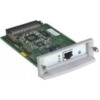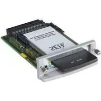
FC1126 - Media player SEH - Free user manual and instructions
Find the device manual for free FC1126 SEH in PDF.


User questions about FC1126 SEH
0 question about this device. Answer the ones you know or ask your own.
Ask a new question about this device
Download the instructions for your Media player in PDF format for free! Find your manual FC1126 - SEH and take your electronic device back in hand. On this page are published all the documents necessary for the use of your device. FC1126 by SEH.
USER MANUAL FC1126 SEH
natural_image
Close-up of a black rectangular electronic device with a U-shaped internal port and two circular connectors attached to its side, showing no visible text or symbols.Overview
This 'User Manual' describes the hardware installation of the FC1126.
Table of contents 12.
Do you need assistance? Contact us!

Monday to Thursday Friday
8:00 a.m. to 4:45 p.m. and 8:00 a.m. to 3:15 p.m. (CET)

+49 (0)521 94226-44

support@seh.de

www.seh-technology.com
Überblick
Before starting the initial operation procedure of your device, please note the following safety regulations:
- Read the documentation and make sure that your system meets the requirements listed therein.
- The device must only be connected to the mains and to the network by qualified personnel.
- Avoid contact with humidity or liquids.
- The device must only be connected and operated if it is in perfect condition.
- Make sure that no-one steps on or stumbles over the cables.
- This is a class 1 laser product. If no cable is connected to the SC or ST connector, invisible laser radiation may occur. Do not expose yourself to laser radiation and do not look straight into it. Put the provided protective caps on the SC or ST connector if you do not use it.
- Before unpacking the device, take all necessary precautions to avoid damage to the device board e.g. electrostatic discharges etc.
Deutsch [de]
Safety Regulations....1
General Information ....13
Purpose....13
Supported Printers....13
Scope of Supply 14
Technical Data....15
LED Display....16
Type Plate....16
Installing the Fiber Adapter ....17
General Information 17
Tools You Need ....18
Step 1: Prepare the printer....18
Step 2: Gain Access to the Printer Mainboard....18
Step 3: Prepare the Printer Mainboard....19
Step 4: Installing the Fiber Adapter ....19
Step 5: Connecting the USB Cable to the Printer Mainboard....21
Step 6: Reinstall Components....21
Step 7: Connect the Fiber Adapter to the Network ....22
Step 8: Turn the Printer On ....22
Regulatory Compliance Information ....35
Purpose
With the Fiber Adapter FC1126 a printer or multi-function printer (MFP) manufactured by Hewlett Packard (HP) can be embedded into an existing fiber-optic network (1000BaseSX to 1000BaseT).
Printer respectively MFP and Fiber Adapter must be compatible; see 'Supported Printers' 13.
In this manual the term 'printer' is used for referring to compatible printers and MFPs.
Supported Printers
You can find a list of supported printers at:
https://www.seh-technology.com/products/fiber-adapter.html
text_image
QR code image containing encoded data, no visible human-readable text
WARNING
Do not connect the Fiber Adapter to other printers!
Please check the package content before getting started:
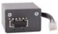
Fiber FC1126
Adapters
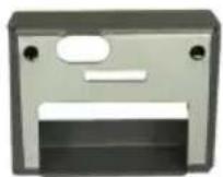
Adaptor Connector
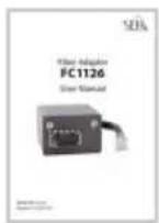
User manual The User Manual describes the installation of the FC1126.
(This document)
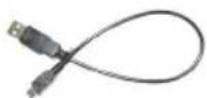
USB cable USB 2.0, connector A on mini-B connector
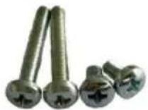
Four screws 2 screws M3 × 5 mm
2 screws M3 × 20 mm
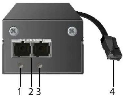
text_image
1 2 3 4- Activity LED (orange)
- Network connector (SC, female)
- Link LED (green)
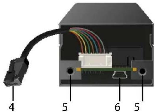
text_image
4 5 6 5- Printer connector (RJ-45, male)
- Hole with thread
- USB port (type: Mini-B)
Properties Values
| Printer port | |
| logical: 1000BaseT Gigabit Ethernet (IEEE 802.3) physical: RJ-45 | |
| Network connection | |
| logical: 1000BaseSX Gigabit Ethernet (IEEE 802.3) physical: SC (type: MMF; 50/125 μm, 62,5/125 μm) | |
| Current input 300 mA at 5 V | |
| Operating environment Ambient temperature: 5–40 °C Relative humidity: 20–80 % | |
| Dimensions Width: 52 mm | |
| Height: 31 mmDepth: 59 mmWeight: 133 g | |
The LEDs of the FC1126 provide information about its status.
| LED Action Color Description | ||
| Activity blinks at irregular intervals | orange | Indicates the exchange of network data packets. |
| Link permanently on | green | There is a connection to the fiber-optic network. |
| permanently off | - | There is no connection to the fiber-optic network. |

Type Plate
The type plate gives important product information, such as hardware and certification information as well as the serial number. The serial number contains the production date: nnn JJJ MM nnnnn.
You need this information for support requests.
General Information
The Fiber Adapter is mounted to the printer mainboard.

Important:
Installation steps may vary slightly depending on printer model:
The Fiber Adapter was developed for a series of supported printer models which vary in design. All printer model specifics cannot be provided for in this manual. Follow the general steps of this manual and adapt them if needed. In case of questions, contact our support team →2!
To mount the Fiber Adapter to the printer mainboard, it is mounted from the outside over a pre-punched and removable cut-out in the panel. The connection to the printer is established via an internal RJ-45 cable. Power is supplied via the USB cable by means of an internal USB port of the printer.

WARNING
The Fiber Adapter must only be installed by qualified personnel.

WARNING
Before mounting the device, take all necessary precautions to avoid electrostatic discharges.

WARNING
The printer circuit board may be damaged if it is touched!
Do not touch the circuit board with hands or tools.
Step 1: 'Prepare the printer' → 18
Step 2: 'Gain Access to the Printer Mainboard' → 18
Step 3: 'Prepare the Printer Mainboard' → 19
Step 4: 'Installing the Fiber Adapter' → 19
Step 5: 'Connecting the USB Cable to the Printer Mainboard' → 21
Step 6: 'Reinstall Components' → 21
Step 7: 'Connect the Fiber Adapter to the Network' → 22
Step 8: 'Turn the Printer On' → 22
Tools You Need
- Flat screwdriver
• Philips screwdriver
• Additional product 'HP Internal USB Ports' B5L28A (depending on printer model)
• Utility knife
• Non-conductive mat (e.g. rubber mat) - Card board
Step 1: Prepare the printer
- Turn the printer off.
- Disconnect the power cord from the printer.
(Interrupt the power supply) - Disconnect the RJ-45 network cable from the printer.
Step 2: Gain Access to the Printer Mainboard
Depending on printer model, you either remove the printer mainboard from the printer or you just uncover it.
Printer Mainboard Can Be Removed:
- Identify the printer mainboard. You can recognize it by the RJ-45 network connector and the other interfaces.
-
Loosen the knurled screws of the printer mainboard.
(With some printer models the knurled screws cannot be removed completely. In this case, loosen them as much as possible.) -
Pull the printer mainboard out of its slot.

WARNING
The printer circuit board may be damaged if it is touched!
Only touch the printer mainboard at its panel.
- Place the printer mainboard on a non-conductive mat (e.g. rubber mat).
- Cover the printer circuit board and the edges of the housing with cardboard in order to avoid injuries to persons and damage to the device.
Printer Mainboard Cannot Be Removed:
- Identify the printer mainboard. You can recognize it by the RJ-45 network connector and the other interfaces.
- Loosen the knurled screws of the printer mainboard's plastic cover.
- Remove the printer mainboard plastic cover.
- Remove the printer mainboard metal cover.
Step 3: Prepare the Printer Mainboard
The printer mainboard panel features a pre-punched metal cut-out and holes near the RJ-45 connector.
- Identify the pre-punched metal cut-out and holes.
-
Depending on printer model, the metal cut-out is concealed on the circuit board side by a hard disk drive. If this is the case, remove the hard disk drive. If the hard disk drive is equipped with a fan, unplug the fan cable from the printer mainboard first. Refer to the documentation of your printer on how to do this.
-
Remove the panel film around the RJ-45 network connector so that the cut-out and the holes are free and that there is no film between the panel and the Fiber Adapter in its final position.
With some printer models, the protective film consists of perforated parts that can be removed individually. With printer models without perforated parts you have to cut the film on your own with a utility knife.
- Remove the pre-punched cut-out. To do this, insert a flat screwdriver into the elongated hole at the cut-out and carefully remove the cut-out by levering it back and forth.
Step 4: Installing the Fiber Adapter
The exact mounting position of the Fiber Adapter varies depending on printer model. In addition, some printer models need the enclosed adaptor.
Installation without Adaptor
- Connect the included USB cable (mini-B connector) to the USB connector of the Fiber Adapter.
- Thread the unconnected end of the USB cable (connector A) from the outside through the cut-out in the panel and make sure it does not touch the printer mainboard.
- Connect the RJ-45 network cable of the Fiber Adapter to the RJ-45 network connector of the printer.

To make things easier, you can gently pull the RJ-45 network cable out of the Fiber Adapter. After connecting the cable, put it back into the housing of the Fiber Adapter.
- Place the Fiber Adapter from the outside above the cut-out in the panel. The holes of the Fiber Adapter and the holes next to the cut-out must align con- gruently.

WARNING
Incorrect positioning may impact the Fiber Adapter's security against interception!
Position the Fiber Adapter as described and make sure that the RJ-45 connector and the panel cut-out are completely covered.

WARNING
The RJ-45 cable and USB cable may be damaged if pinched!
Make sure that your cable management does not pinch or squeeze the cables.
- Screw the Fiber Adapter to the panel with the enclosed short screws (M3 × 5 mm).
Installation with Adaptor
- Carefully pull the RJ-45 cable slightly out of the Fiber Adapter.
- Connect the included USB cable (mini-B connector) to the USB connector of the Fiber Adapter.
- Thread the enclosed USB cable through the oblong hole in the adaptor.
- Thread the RJ-45 cable through the oblong hole in the adaptor.
- Position the adaptor over the Fiber Adapter:
- The little wings of the adaptor go into the Fiber Adapter.
– The holes of the adaptor and Fiber Adapter are congruent. - The USB cable is threaded though the oblong hole in the adaptor.
- The RJ-45 cable is threaded though the biggest hole in the adaptor.

WARNING
The Fiber Adapter circuit board may be damaged if it is touched by the adaptor!
Position the adaptor very carefully on the Fiber Adapter, so that adaptor and circuit board do not touch.
- Thread the unconnected end of the USB cable (connector A) from the outside through the cut-out in the panel and make sure it does not touch the printer mainboard.
- Connect the RJ-45 network cable of the Fiber Adapter to the RJ-45 network connector of the printer.
- Place the Fiber Adapter from the outside above the cut-out in the panel. The holes of the Fiber Adapter and the holes next to the cut-out must align con- gruently.
- Screw the Fiber Adapter to the panel with the enclosed short screws (M3 × 20 mm). The screws must go through the adaptor into the holes of the
Fiber Adapter.
Step 5: Connecting the USB Cable to the Printer Mainboard
To supply the Fiber Adapter with power, it is connected to the printer mainboard via USB connection.
To do this, you connect the free end of the USB cable (connector A) to the next available USB port on the printer mainboard circuit board.
Some printers do not have a free USB port. In this case, you have to use the additional HP product 'HP Internal USB Ports' (B5L28A). For information on how to install it, read the documentation of the additional product.
If you covered the circuit board and edged of the printer mainboard housing with cardboard in step 2, remove these after you have connected the USB cable.
Step 6: Reinstall Components
If you removed the printer mainboard respectively the printer mainboard cover(s) in step 2 or if you removed the hard disk drive in step 3, you have reinstall these components.

WARNING
The USB cable and other cables may be damaged if pinched!
Make sure that your cable management does not pinch or squeeze the cables when you reinstall the components.
Reinstall the Printer Mainboard
- Put the printer mainboard back into the slot provided in the printer.
- Tighten the knurled screws of the printer mainboard.
Reinstall Printer Mainboard Cover(s)
- Put the metal cover for the printer mainboard back into the slot provided in the printer.
- Tighten the knurled screws of the metal cover.
- Put the plastic cover for the printer mainboard back into the slot provided in the printer.
- Tighten the knurled screws of the plastic cover.
Reinstall Hard Disk Drive
Reinstall the printer's hard disk drive. If the hard disk drive is equipped with a fan, reconnect the fan cable to the printer mainboard to its intended connector. Refer to the documentation of your printer on how to do this. Falls die
Step 7: Connect the Fiber Adapter to the Network
- Remove the protective cap of the SC connector.

Important:
Do not throw away the protective cap! Put the protective cap on the SC connector if it is not in use.
- Connect the fiber optic cable of your network (SC connector) to the network connector (SC, female) of the Fiber Adapter.
Step 8: Turn the Printer On
-
Connect the power cord to the printer. (Establish the power supply)
-
Turn the printer on. → Printer and Fiber Adapter are ready for use.
text_image
QR code image containing encoded data, no visible human-readable text
WARNUNG
The latest version of the EC declaration of conformity can be downloaded from the homepage of SEH Computertechnik GmbH:
http://www.seh-technology.com/services/
ce-notifications.html
Manufacturer's Name
Manufacturer's Address
Suedring 11
33647 Bielefeld
Germany
Phone ++49 (0) 521 - 94226-0

text_image
SEHEC – Declaration of Conformity
Herewith SEH Computertechnik GmbH declares that
Product: Built-In Fiber-Adapter
Type designation: FC1126
Serial No.: 269 yyyy mm nnnnn (yyyy = year, mm = month, nnnnn = seq. no.)
is in conformity with the provisions of the
DIRECTIVE 2014/30/EU OF THE EUROPEAN PARLIAMENT AND OF THE COUNCIL OF 26 FEBRUARY 2014 on the harmonisation of the laws of the Member States relating to electromagnetic compatibility (recast)
DIRECTIVE 2011/65/EU OF THE EUROPEAN PARLIAMENT AND OF THE COUNCIL OF 8 JUNE 2011 on the restriction of the use of certain hazardous substances in electrical and electronic equipment
Standards applied:
EN 55024:2010
EN 55032:2012 Class B
EN 50581:2012
The named device is not intended primarily for use in domestic environments.
To meet the above specifications, the user has to comply with all instructions defined in the enclosed manual Hardware Installation Guide.
Bielefeld, March 3, 2017
Rain Celler
Dipl.-Ing. Rainer Ellerbrake, General Manager
Federal Communication Commission (FCC) Notice
The user has to comply with all instructions defined in this manual. It is not allowed to do product modifications not expressly approved by SEH.
Note:
This equipment has been tested and found to comply with the limits for a Class B digital device, pursuant to part 15 of the FCC Rules. These limits are designed to provide reasonable protection against harmful interference in a residential installation.
This equipment generates, uses and can radiate radio frequency energy and, if not installed and used in accordance with the instructions, may cause harmful interference to radio communications. However, there is no guarantee that interference will not occur in a particular installation.
If this equipment does cause harmful interference to radio or television reception, which can be determined by turning the equipment off and on, the user is encouraged to try to correct the interference by one or more of the following measures:
- Reorient or relocate the receiving antenna.
— Increase the separation between the equipment and receiver. - Connect the equipment into an outlet on a circuit different from that to which the receiver is connected.
- Consult the dealer or an experienced radio/TV technician for help.
Manufacturer:
33647 Bielefeld, Germany
Phone: +49 (0)521 94226-29
Fax: +49 (0)521 94226-99
Support: +49 (0)521 94226-44
Email: info@seh.de
text_image
QR code image containing encoded data, no visible human-readable textImportant Internet Resources:
Support Contacts and Information:
http://www.seh-technology.com/support
Sales Contacts and Information:
http://www.seh-technology.com/sales
Downloads:
http://www.seh-technology.com/services/downloads.html

All trademarks, registered trademarks, logos and product names are property of their respective owners.
The contents of this document are subject to change without notification.
The product documentation gives you valuable information about your product. Keep the documentation for further reference during the life cycle of the product.