
Latitude 7380 - Laptop DELL - Free user manual and instructions
Find the device manual for free Latitude 7380 DELL in PDF.


| Product Type | Laptop (Notebook) |
| Model | Dell Latitude 7380 |
| Dimensions (Width x Depth x Height) | 304.8 mm x 207.95 mm x 16.7 mm (front) / 19.95 mm (rear) |
| Weight | Starting at 1.17 kg (2.59 lb) |
| Processor Options | 7th Generation Intel Core i3/i5/i7 or 6th Generation Intel Core i5/i7 |
| Memory | Up to 16 GB DDR4 2133 MHz (1 SO-DIMM slot) |
| Storage Options | M.2 PCIe SSD or SATA SSD (up to 1 TB typical) |
| Display | 13.3-inch FHD (1920 x 1080) anti-glare or touch, 300 nits |
| Graphics | Intel HD Graphics 620 (7th gen) or 520 (6th gen) |
| Operating System | Windows 10 Pro/Home, Windows 7 Pro, Ubuntu 16.04, NeoKylin |
| Battery | 3-cell 42 Wh or 4-cell 60 Wh lithium prismatic with ExpressCharge |
| AC Adapter | 65 W or 90 W, input 100-240 V AC, output 19.5 V DC |
| Ports | 2x USB 3.1 Gen1 (1 PowerShare), 1x USB Type-C (DisplayPort/Thunderbolt 3 optional), HDMI 1.4, RJ-45, audio combo, MicroSD reader, uSIM slot |
| Wireless | WLAN (802.11ac), Bluetooth, optional WWAN (4G LTE), WiGig |
| Keyboard | Standard backlit keyboard with optional fingerprint reader |
| Security | TPM 2.0, Computrace, smart card reader (optional), fingerprint sensor (optional), IR camera for Windows Hello |
| Maintenance & Cleaning | Use anti-static mat, disconnect AC, hold power button to discharge residual power, clean with soft dry cloth |
| Repairability | Serviceable: base cover, battery, SSD, memory, WLAN/WWAN, fan, speaker, display assembly, system board, keyboard |
| Environmental | Operating temperature: 0°C to 60°C; storage: -51°C to 71°C |
Frequently Asked Questions - Latitude 7380 DELL
User questions about Latitude 7380 DELL
0 question about this device. Answer the ones you know or ask your own.
Ask a new question about this device
Download the instructions for your Laptop in PDF format for free! Find your manual Latitude 7380 - DELL and take your electronic device back in hand. On this page are published all the documents necessary for the use of your device. Latitude 7380 by DELL.
USER MANUAL Latitude 7380 DELL
Notes, cautions, and warnings
NOTE: A NOTE indicates important information that helps you make better use of your product.
CAUTION: A CAUTION indicates either potential damage to hardware or loss of data and tells you how to avoid the problem.
WARNING: A WARNING indicates a potential for property damage, personal injury, or death.
© 2017 Dell Inc. or its subsidiaries. All rights reserved. Dell, EMC, and other trademarks are trademarks of Dell Inc. or its subsidiaries. Other trademarks may be trademarks of their respective owners.
Working on your computer
Safety precautions
The safety precautions chapter details the primary steps to be taken before performing any disassembly instructions.
Observe the following safety precautions before you perform any installation or break/fix procedures involving disassembly or reassembly:
- Turn off the system and all attached peripherals.
- Disconnect the system and all attached peripherals from AC power.
- Disconnect all network cables, telephone, and telecommunications lines from the system.
• Use an ESD field service kit when working inside any tablet to avoid electrostatic discharge (ESD) damage. - After removing any system component, carefully place the removed component on an anti-static mat.
- Wear shoes with non-conductive rubber soles to reduce the chance of getting electrocuted.
Standby power
Dell products with standby power must be unplugged before you open the case. Systems that incorporate standby power are essentially powered while turned off. The internal power enables the system to be remotely turned on (wake on LAN) and suspended into a sleep mode and has other advanced power management features.
After unplugging, pressing and holding the power button for 15 seconds should discharge residual power in the system board. tablets.
Bonding
Bonding is a method for connecting two or more grounding conductors to the same electrical potential. This is done through the use of a field service electrostatic discharge (ESD) kit. When connecting a bonding wire, ensure that it is connected to bare metal and never to a painted or non-metal surface. The wrist strap should be secure and in full contact with your skin, and ensure that you remove all jewelry such as watches, bracelets, or rings prior to bonding yourself and the equipment.
Electrostatic discharge (ESD) protection
ESD is a major concern when you handle electronic components, especially sensitive components such as expansion cards, processors, memory DIMMs, and system boards. Very slight charges can damage circuits in ways that may not be obvious, such as intermittent problems or a shortened product life span. As the industry pushes for lower power requirements and increased density, ESD protection is an increasing concern.
Due to the increased density of semiconductors used in recent Dell products, the sensitivity to static damage is now higher than in previous Dell products. For this reason, some previously approved methods of handling parts are no longer applicable.
Two recognized types of ESD damage are catastrophic and intermittent failures.
- Catastrophic – Catastrophic failures represent approximately 20 percent of ESD-related failures. The damage causes an immediate and complete loss of device functionality. An example of catastrophic failure is a memory DIMM that has received a static shock and immediately generates a "No POST/No Video" symptom with a beep code emitted for missing or nonfunctional memory.
- Intermittent – Intermittent failures represent approximately 80 percent of ESD-related failures. The high rate of intermittent failures means that most of the time when damage occurs, it is not immediately recognizable. The DIMM receives a static shock, but the
tracing is merely weakened and does not immediately produce outward symptoms related to the damage. The weakened trace may take weeks or months to melt, and in the meantime may cause degradation of memory integrity, intermittent memory errors, etc.
The more difficult type of damage to recognize and troubleshoot is the intermittent (also called latent or "walking wounded") failure.
Perform the following steps to prevent ESD damage:
- Use a wired ESD wrist strap that is properly grounded. The use of wireless anti-static straps in no longer allowed; they do not provide adequate protection. Touching the chassis before handling parts does not ensure adequate ESD protection on parts with increased sensitivity to ESD damage.
- Handle all static-sensitive components in a static-safe area. If possible, use anti-static floor pads and workbench pads.
- When unpacking a static-sensitive component from its shipping carton, do not remove the component from the anti-static packing material until you are ready to install the component. Before unwrapping the anti-static packaging, be sure ensure that you discharge static electricity from your body.
- Before transporting a static-sensitive component, place it in an anti-static container or packaging.
ESD field service kit
The unmonitored Field Service kit is the most commonly used service kit. Each Field Service kit includes three main components: anti-static mat, wrist strap, and bonding wire.
Components of an ESD field service kit
The components of an ESD field service kit are:
- Anti-Static Mat – The anti-static mat is dissipative and parts can be placed on it during service procedures. When using an anti-static mat, your wrist strap should be snug and the bonding wire should be connected to the mat and to any bare metal on the system being worked on. Once deployed properly, service parts can be removed from the ESD bag and placed directly on the mat. ESD-sensitive items are safe in your hand, on the ESD mat, in the system, or inside a bag.
- Wrist Strap and Bonding Wire – The wrist strap and bonding wire can be either directly connected between your wrist and bare metal on the hardware if the ESD mat is not required, or connected to the anti-static mat to protect hardware that is temporarily placed on the mat. The physical connection of the wrist strap and bonding wire between your skin, the ESD mat, and the hardware is known as bonding. Use only Field Service kits with a wrist strap, mat, and bonding wire. Never use wireless wrist straps. Always be aware that the internal wires of a wrist strap are prone to damage from normal wear and tear, and must be checked regularly with a wrist strap tester in order to avoid accidental ESD hardware damage. It is recommended to test the wrist strap and bonding wire at least once per week.
- ESD Wrist Strap Tester – The wires inside of an ESD strap are prone to damage over time. When using an unmonitored kit, it is a best practice to regularly test the strap prior to each service call, and at a minimum, test once per week. A wrist strap tester is the best method for doing this test. If you do not have your own wrist strap tester, check with your regional office to find out if they have one. To perform the test, plug the wrist-strap's bonding-wire into the tester while it is strapped to your wrist and push the button to test. A green LED is lit if the test is successful; a red LED is lit and an alarm sounds if the test fails.
- Insulator Elements – It is critical to keep ESD sensitive devices, such as plastic heat sink casings, away from internal parts that are insulators and often highly charged.
- Working Environment – Before deploying the ESD Field Service kit, assess the situation at the customer location. For example, deploying the kit for a server environment is different than for a desktop or portable environment. Servers are typically installed in a rack within a data center; desktops or portables are typically placed on office desks or cubicles. Always look for a large open flat work area that is free of clutter and large enough to deploy the ESD kit with additional space to accommodate the type of system that is being repaired. The workspace should also be free of insulators that can cause an ESD event. On the work area, insulators such as Styrofoam and other plastics should always be moved at least 12 inches or 30 centimeters away from sensitive parts before physically handling any hardware components
- ESD Packaging – All ESD-sensitive devices must be shipped and received in static-safe packaging. Metal, static-shielded bags are preferred. However, you should always return the damaged part using the same ESD bag and packaging that the new part arrived in. The ESD bag should be folded over and taped shut and all the same foam packing material should be used in the original box that the new part arrived in. ESD-sensitive devices should be removed from packaging only at an ESD-protected work surface, and parts should never be placed on top of the ESD bag because only the inside of the bag is shielded. Always place parts in your hand, on the ESD mat, in the system, or inside an anti-static bag.
- Transporting Sensitive Components – When transporting ESD sensitive components such as replacement parts or parts to be returned to Dell, it is critical to place these parts in anti-static bags for safe transport.
ESD protection summary
It is recommended that all field service technicians use the traditional wired ESD grounding wrist strap and protective anti-static mat at all times when servicing Dell products. In addition, it is critical that technicians keep sensitive parts separate from all insulator parts while performing service and that they use anti-static bags for transporting sensitive components.
Before working inside your computer
1 Ensure that your work surface is flat and clean to prevent the computer cover from being scratched.
2 Turn off your computer.
3 If the computer is connected to a docking device (docked), undock it.
4 Disconnect all network cables from the computer (if available).
CAUTION: If your computer has an RJ45 port, disconnect the network cable by first unplugging the cable from your computer.
5 Disconnect your computer and all attached devices from their electrical outlets.
6 Open the display.
7 Press and hold the power button for few seconds, to ground the system board.
CAUTION: To guard against electrical shock unplug your computer from the electrical outlet before performing Step #8.
CAUTION: To avoid electrostatic discharge, ground yourself by using a wrist grounding strap or by periodically touching an unpainted metal surface at the same time as touching a connector on the back of the computer.
8 Remove any installed ExpressCards or Smart Cards from the appropriate slots.
Turning off your computer
Turning off your computer — Windows 10

CAUTION: To avoid losing data, save and close all open files and exit all open programs before you turn off your computer.

1 Click or tap
2 Click or tap and then click or tap Shut down.
NOTE: Ensure that the computer and all attached devices are turned off. If your computer and attached devices did not automatically turn off when you shut down your operating system, press and hold the power button for about 6 seconds to turn them off.
Turning off your computer — Windows 7

CAUTION: To avoid losing data, save and close all open files and exit all open programs before you turn off your computer.
1 Click Start.
2 Click Shut Down.

NOTE: Ensure that the computer and all attached devices are turned off. If your computer and attached devices did not automatically turn off when you shut down your operating system, press and hold the power button for about 6 seconds to turn them off.
After working inside your computer
After you complete any replacement procedure, ensure that you connect external devices, cards, and cables before turning on your computer.

CAUTION: To avoid damage to the computer, use only the battery designed for this particular Dell computer. Do not use batteries designed for other Dell computers.
1 Connect any external devices, such as a port replicator or media base, and replace any cards, such as an ExpressCard.
2 Connect any telephone or network cables to your computer.

CAUTION: To connect a network cable, first plug the cable into the network device and then plug it into the computer.
3 Connect your computer and all attached devices to their electrical outlets.
4 Turn on your computer.
Removing and installing components
This section provides detailed information on how to remove or install the components from your computer.
Recommended tools
The procedures in this document require the following tools:
• Phillips #0 screwdriver
- Phillips #1 screwdriver
- Small plastic scribe
Screw size list
Table 1. Latitude 7380 - screw size list
| Component M2.5x 6.0 | M2.0 x 5.0 M2.5 x 4.0 | M2.0x3.0 M2.0 x 2.5 M2.0 x 2.0 | ||||
| Back cover 8 (captive screws) | ||||||
| Battery—3-cell 1 | ||||||
| Battery—4-cell 2 | ||||||
| SSD module 1 | ||||||
| Heat sink module 4 | ||||||
| System fan 2 | ||||||
| Speaker 4 | ||||||
| WWAN card | 1 | |||||
| WLAN card | 1 | |||||
| Power connector port | 1 | |||||
| ESD bracket | 1 | |||||
| EDP bracket | 2 | |||||
| LED board | 1 | |||||
| Smart card reader cage | 2 | |||||
| Display hinge | 6 | |||||
| Keyboard support plate | 19 | |||||
| Keyboard | 5 | |||||
| System board | 8 | |||||
| Memory module bracket | 1 | |||||
Subscriber Identification Module (SIM) card
Removing SIM card or SIM card tray

NOTE: SIM card or SIM card tray removal is only available on systems that are shipped with WWAN module. Hence, removing procedure is only applicable for systems that are shipped with WWAN module.

CAUTION: Removing the SIM card when the computer is On, may cause data loss or damage the card. Ensure that your computer is turned off or the network connections are disabled.
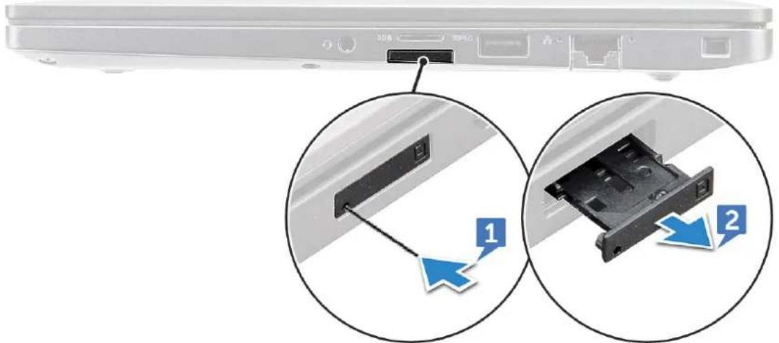
1 Insert a paperclip or a SIM card removal tool into the pinhole on the SIM card tray.
2 Use a scribe to pull the SIM card tray.
3 If a SIM card is available, remove the SIM card from the SIM card tray.
natural_image
Close-up of a laptop rear panel showing a USB drive and a physical drive component, with two circular arrows indicating direction (no text or symbols present)Replacing SIM card

NOTE: You can replace a SIM card only for those systems that are shipped with WWAN module.
1 Insert a paperclip or a SIM card removal tool into the pinhole on the SIM card tray.
2 Use a scribe to pull the SIM card tray.
3 Place on the SIM card on the tray.
4 Insert the SIM card tray into the slot.
Dummy SIM-card tray removal
For models shipped with a WWAN card, the SIM card tray be removed from the system before removing the system board. To remove the SIM card tray from the system, see removing SIM card tray
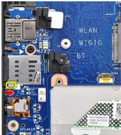
For models shipped with a Wireless card only, a dummy SIM card tray must be removed before removing the system board. The following are the steps for removing the dummy SIM card tray:
1 Push the release latch on the SIM card slot inwards.
text_image
WLAN WIGIG BT M2X3 8 SPEAKER X32 Slide the dummy SIM card tray out of the system.
Base cover
Removing base cover
1 Follow the procedure in Before working inside your computer.
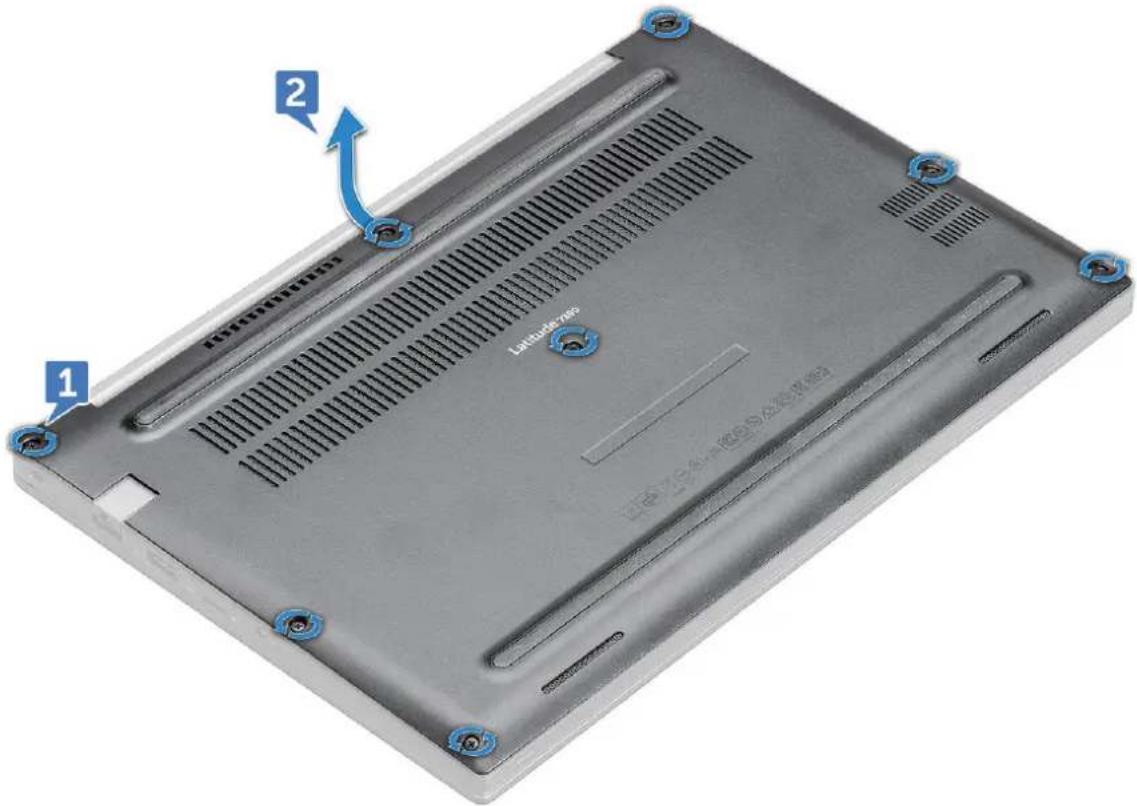
2 To release the base cover:
a
Remember: Exercise caution when loosening the screws. Angle the screw driver to match the head of the screw to avoid a possible stripped screw head.
Loosen the M2.5 x 6.0 captive screws that secure the base cover to the computer [1].
b Use a plastic scribe to release the base cover from the edge of the computer as show in the figure [2].
text_image
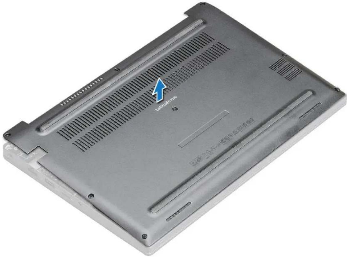
Latitude700 1 23 Lift the base cover from the computer.
text_image
Latitude720° WEDEN SAU-TESS/公差值驱动Installing base cover
1 Align the base cover tabs to the slots on the edges of the computer.
2 Press the edges of the cover until it clicks into place.
3 Tighten the M2.5 x 6.0 captive screws to secure the base cover to the computer.
Remember: Exercise caution when tightening the screws. Angle the screw driver to match the head of the screw to avoid a possible stripped screw head.
4 Follow the procedure in After working inside your computer.
Battery
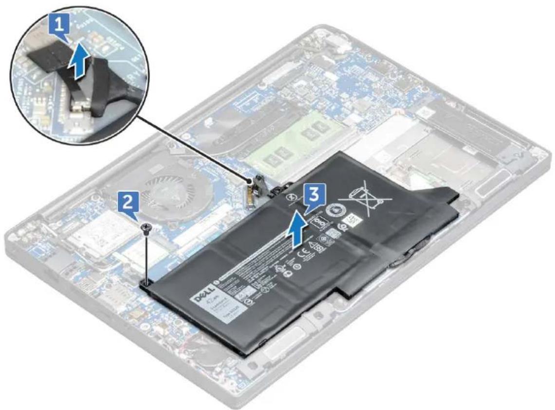
Removing 3-cell battery
1 Follow the procedure in Before working inside your computer.
2 Remove the base cover.
3 To remove the battery:
a Disconnect the battery cable from the connector on the system board [1].
b Remove the M2.0 x 5.0 screw that secures the battery to the computer [2].
c Lift the battery from the computer [3].
text_image
Diagram of an energy storage module with labeled components and a magnified inset showing a battery assembly.Installing 3-cell battery
1 Insert the battery into the slot on the computer.
2 Route the battery cable through the routing clip and connect the battery cable to the connector on the system board.
NOTE: Route the battery cable, if the cable at the base of the battery is unrouted.
3 Tighten the M2.0 x 5.0 screw to secure the battery to the computer.
4 Install the base cover
5 Follow the procedure in After working inside your computer.
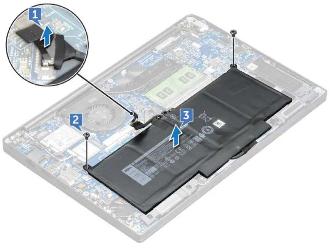
Removing 4-cell battery
1 Follow the procedure in Before working inside your computer.
2 Remove the base cover.
3 To remove the battery:
a Disconnect the battery cable from the connector on the system board [1]. b Remove the two M2.0 x 5.0 screws that secure the battery to the computer [2]. c Lift the battery from the computer [3].
text_image
Diagram of an electronic device showing battery pack, circuit board, and labeled components with numbered annotationsInstalling 4-cell battery
1 Insert the battery into the slot on the computer.
2 Route the battery cable through the routing clip and connect the battery cable to the connector on the system board.
NOTE: Route the battery cable, if the cable at the base of the battery is un routed.
3 Tighten the two M2.0 x 5.0 screws to secure the battery to the computer.
4 Install the base cover
5 Follow the procedure in After working inside your computer.
PCIe Solid State Drive (SSD)
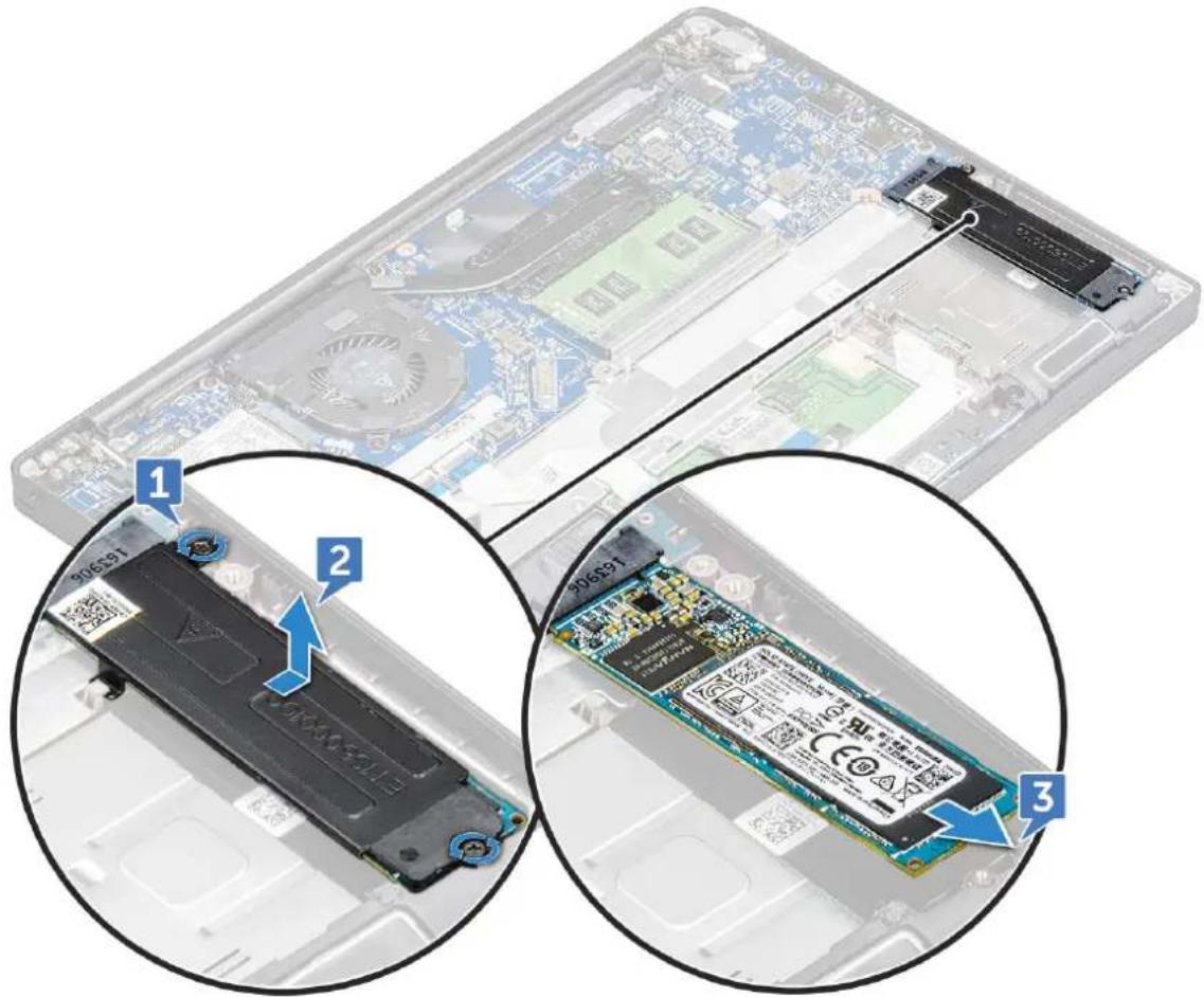
Removing PCIe SSD
1 Follow the procedure in Before working inside your computer.
2 Remove the base cover.
3 To remove the PCIe SSD:
a Loosen the M2.0x3.0 captive screws that secure the SSD bracket [1].
b Remove the SSD bracket [2].
c Slightly lift the SSD and pull out from its connector.
text_image
Diagram showing three views of an electronic device with labeled components: battery pack, RAM slots, and I/O chip.Installing PCIe SSD
1 Insert the PCIe SSD card into the connector.
2 Install the SSD bracket over the PCIe SSD card.
NOTE: When installing the SSD bracket, ensure that the tab on the bracket is held securely with the tab on the palm rest.
3 Tighten the M2.0x3.0 screws to secure it the SSD bracket.
4 Install the base cover.
5 Follow the procedure in After working i inside your computer.
SATA Solid State Drive (SSD)
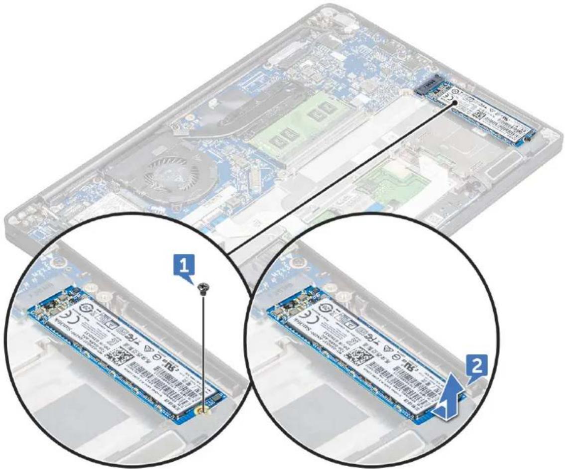
Removing SATA SSD
1 Follow the procedure in Before working inside your computer.
2 Remove the base cover.
3 To remove the SATA SSD:
a Remove the M2.0x3.0 screw that secures the SSD [1].
b Slide and lift the SSD to disconnect it from the connector [2].
text_image
Diagram showing two views of a computer RAM module with labeled pins and a close-up of its internal structure.Installing SATA SSD
1 Insert the SATA SSD card into the connector.
2 Tighten the screw to secure the SATA SSD to the system board.
3 Install the base cover.
4 Follow the procedure in After working inside your computer.
Speaker
Removing speaker module
1 Follow the procedure in Before working inside your computer.
2 Remove the:
a base cover
b battery
3 To release the speaker module:
a Disconnect the speaker cable from the connector on the system board [1].

NOTE: Use a plastic scribe to release the cable from the connector. Do not pull the cable as it may result in breakage
b Un-route the speaker cable from the routing clips [2,3].
c Remove the tape that secures the speaker cables to the touchpad board [4].
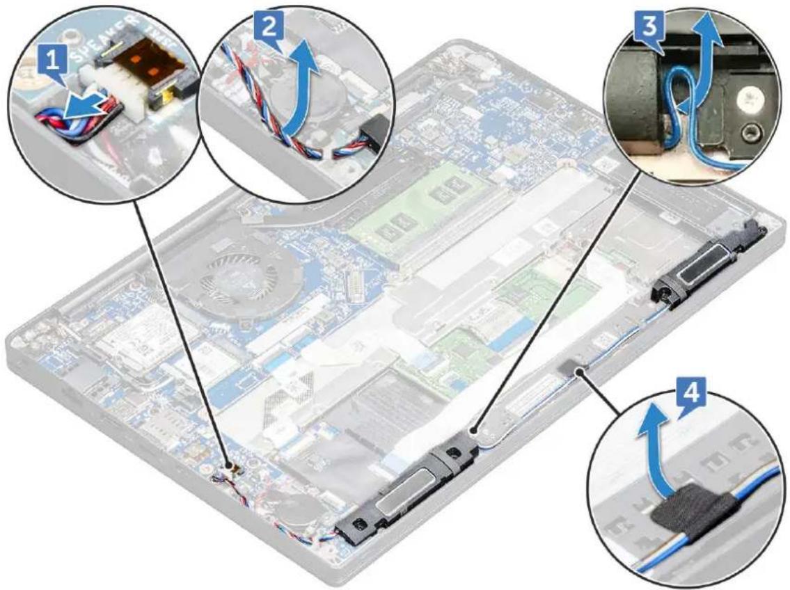
text_image
Diagram showing four steps of cable installation on a computer motherboard, with numbered annotations indicating connection to components.4 To remove the speaker module:
a Remove the M2.0x3.0 screws that secure the speaker module to the computer [1].

NOTE: Refer the speaker screw list
b Lift the speaker module from the computer.
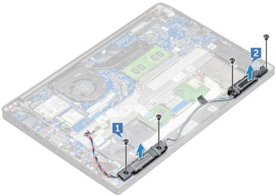
text_image
Laptop screen with cable routing diagram showing two labeled connectors (1 and 2) connected to a central CPU board.Installing speaker module
1 Place the speaker module into the slots on the computer.
2 Tighten the M2.0x3.0 screws to secure the speaker to the computer.
3 Route the speaker cable through the retention clips on the computer.
4 Connect the speaker cable to the connector on the system board.
5 Install the:
a battery
b base cover
6 Follow the procedure in After working inside your computer.
Coin cell battery
Removing the coin cell battery
1 Follow the procedure in Before working inside your computer.
2 Remove the base cover.
3 To remove the coin cell battery:
a Disconnect the coin cell battery cable from the connector on the system board [1].
b Lift the coin cell battery to release it from the adhesive [2].
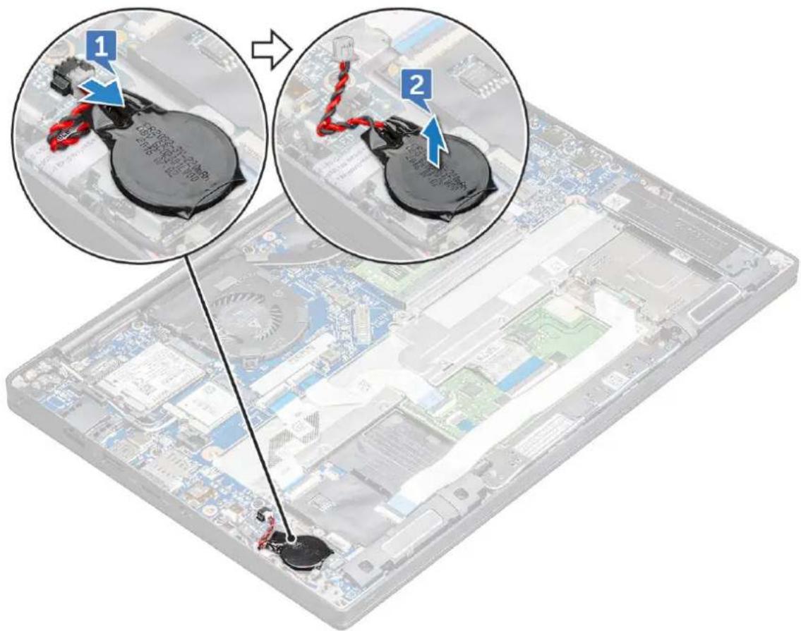
text_image
Diagram showing two views of a computer motherboard with labeled components and a close-up of the device's internal components.Installing coin cell battery
1 Affix the coin cell battery on the slot inside the computer.
2 Route the coin cell battery cable through the routing channel before connecting the cable.
3 Connect the coin cell battery cable to the connector on the system board.
4 Install the base cover.
5 Follow the procedure in After working inside your computer.
WWAN card
Removing WWAN card
1 Follow the procedure in Before working inside your computer.
2 Remove the base cover.
3 To remove the WWAN card:
a Remove the M2.0 x 3.0 screw that secures the metal bracket to the WWAN card.
b Lift the metal bracket that secures the WWAN card.
c Disconnect the WWAN cables from the connectors on the WWAN card.
d Lift the WWAN card out of its connector.
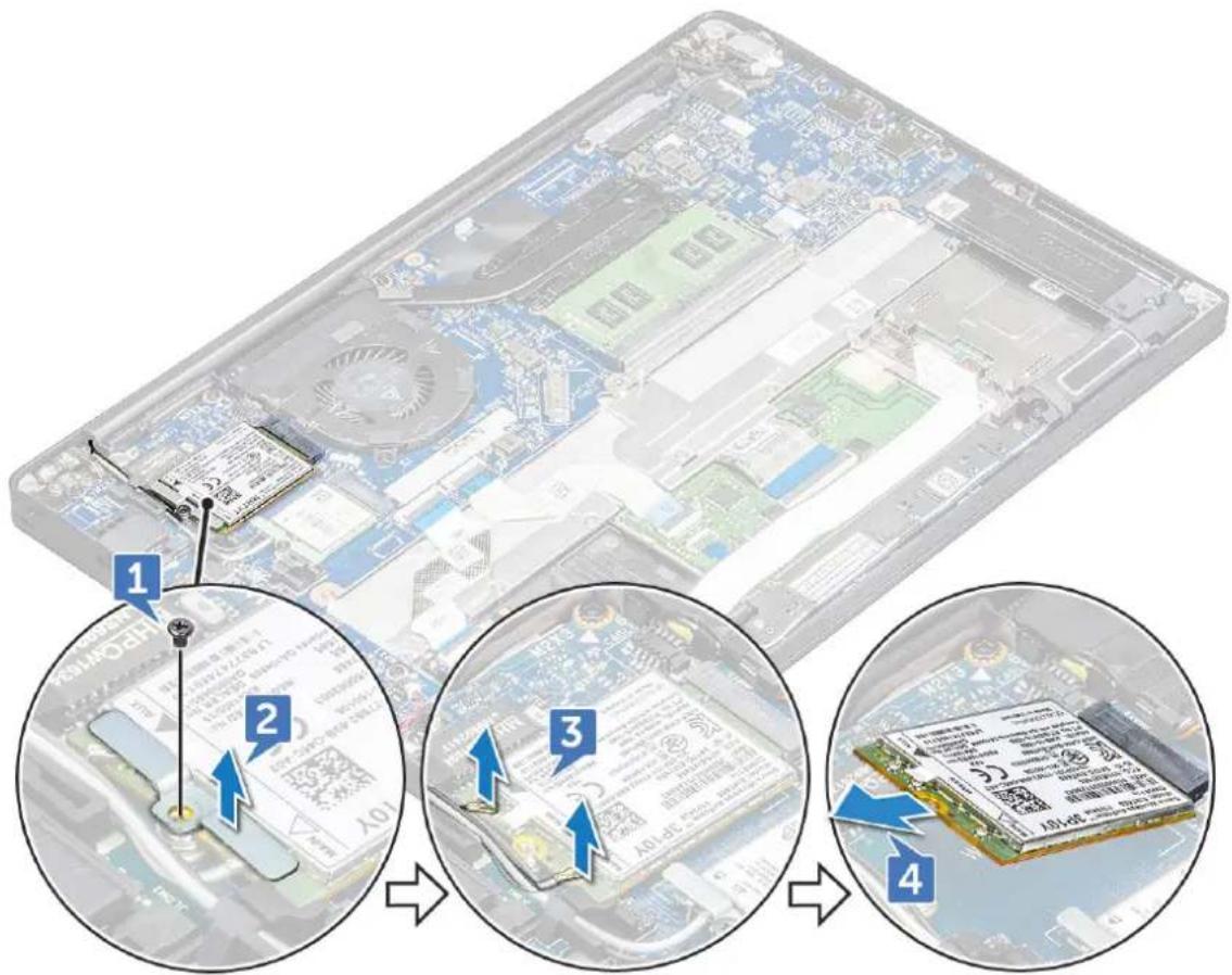
text_image
Diagram showing a device's internal structure and four-step assembly steps with labeled parts and arrows indicating steps.Installing WWAN card
1 Insert the WWAN card into the connector on the system board.
2 Connect the WWAN cables to the connectors on the WWAN card.
3 Place the metal bracket and tighten the M2.0 x 3.0 screw to secure it to the computer.
4 Install the base cover.
5 Follow the procedure in After working inside your computer.
NOTE: The IMEI number can also be found on the WWAN card.
WLAN card
Removing WLAN card
1 Follow the procedure in Before working inside your computer.
2 Remove the base cover.
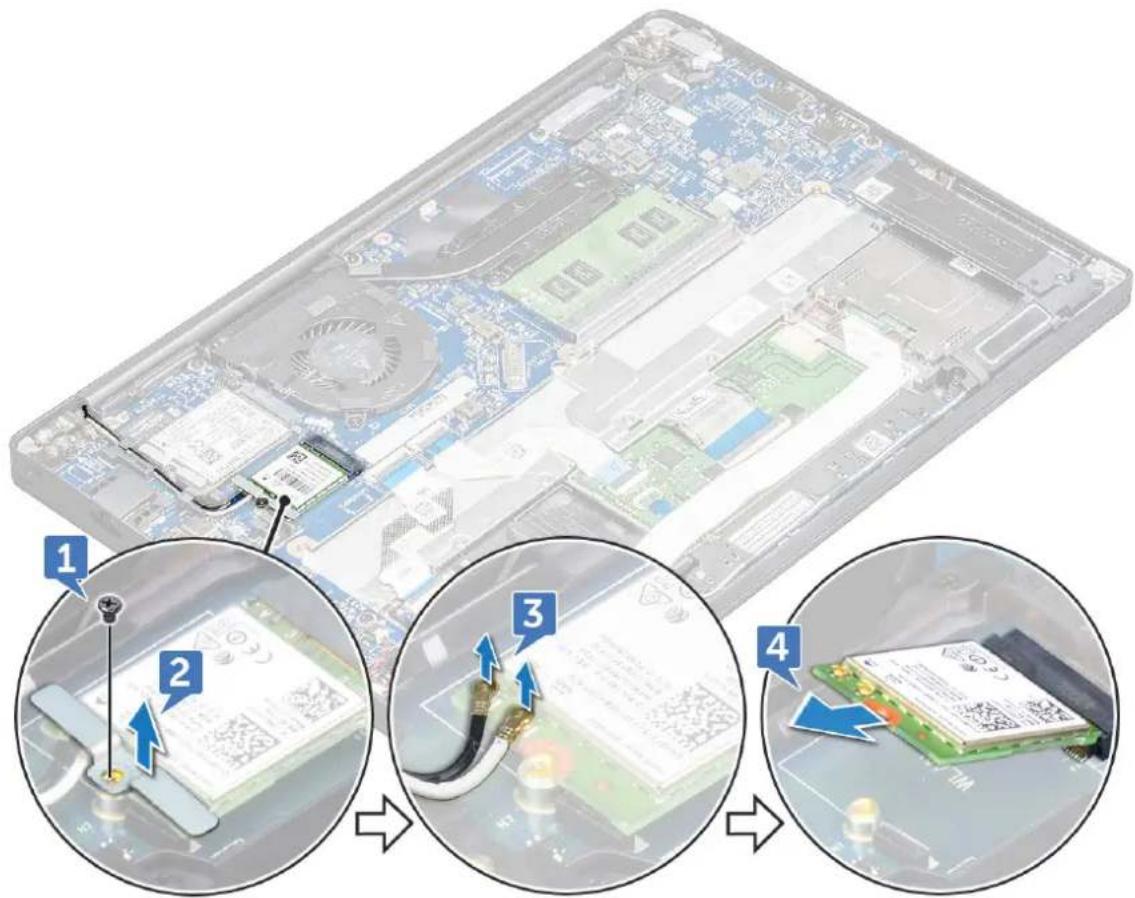
3 To remove the WLAN card:
a Remove the M2.0 x 3.0 screw that secures the metal bracket to the WLAN card [1].
b Lift the metal bracket [2].
c Disconnect the WLAN cables from the connectors on the WLAN card [3].
d Pull the WLAN card out of its connector on the system board [2].
text_image
Diagram showing four steps of inserting a device into a motherboard, with numbered annotations indicating each step.Installing WLAN card
1 Insert the WLAN card into the connector on the system board.
2 Connect the WLAN cables to the connectors on the WLAN card.
3 Place the metal bracket and tighten the M2.0 x 3.0 screw to secure it to the computer.
4 Install the base cover.
5 Follow the procedure in After working inside your computer.
Memory module
Removing memory module
1 Follow the procedure in Before working inside your computer.
2 Remove the base cover.
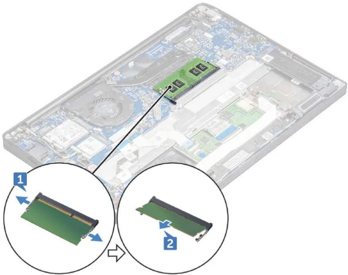
3 To remove the memory module:
a Pull the clips securing the memory module until the module snaps-out [1]. b Remove the memory module from the connector on the system board [2].
natural_image
Illustration of a computer motherboard with two views showing internal components and a close-up of a RAM module (no text or symbols present)Installing memory module
1 Insert the memory module into the connector until snaps in.
2 Install the base cover.
3 Follow the procedures in After working inside your computer.
Heat sink
Removing heat sink assembly
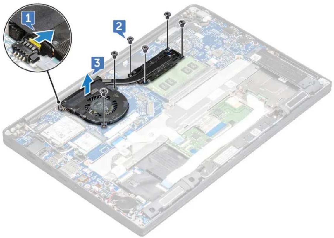
Heat sink assembly comprises of heat sink and the system fan.
1 Follow the procedure in Before working inside your computer.
2 Remove the base cover.
3 To remove the heat sink assembly:

NOTE: To identify the number of screws, see screw list.
a Disconnect the fan cable from the system board [1].
b Remove the M2.0 x 5.0 screws that secure the heat sink and the M2.0 x 3.0 screws that secure the fan to the system board [2].

NOTE: Remove the screws in the order of the callout numbers [1, 2, 3, 4] as indicated on the heat sink.
c Lift the heat sink assembly from the system board [3].
text_image
Labeled diagram of a computer motherboard showing three components: fan, drive, and battery, with an inset magnified view highlighting the component.Installing heat sink assembly
Heat sink assembly comprises of heat sink and the system fan.
1 Align the heat sink assembly with screw holders on the system board.
2 Tighten the M2.0 x 3.0 screws to secure the heat sink to the system board.
NOTE: Tighten the screws in the order of the callout numbers [1, 2, 3, 4] as indicated on the heat sink.
3 Tighten the M2.0 x 5.0 screws to secure the fan to the system board
4 Connect the fan cable to the connector on the system board.
5 Install the base cover.
6 Follow the procedure in After working inside your computer.
Power connector port
Removing power connector port
1 Follow the procedure in Before working inside your computer.
2 Remove the base cover.
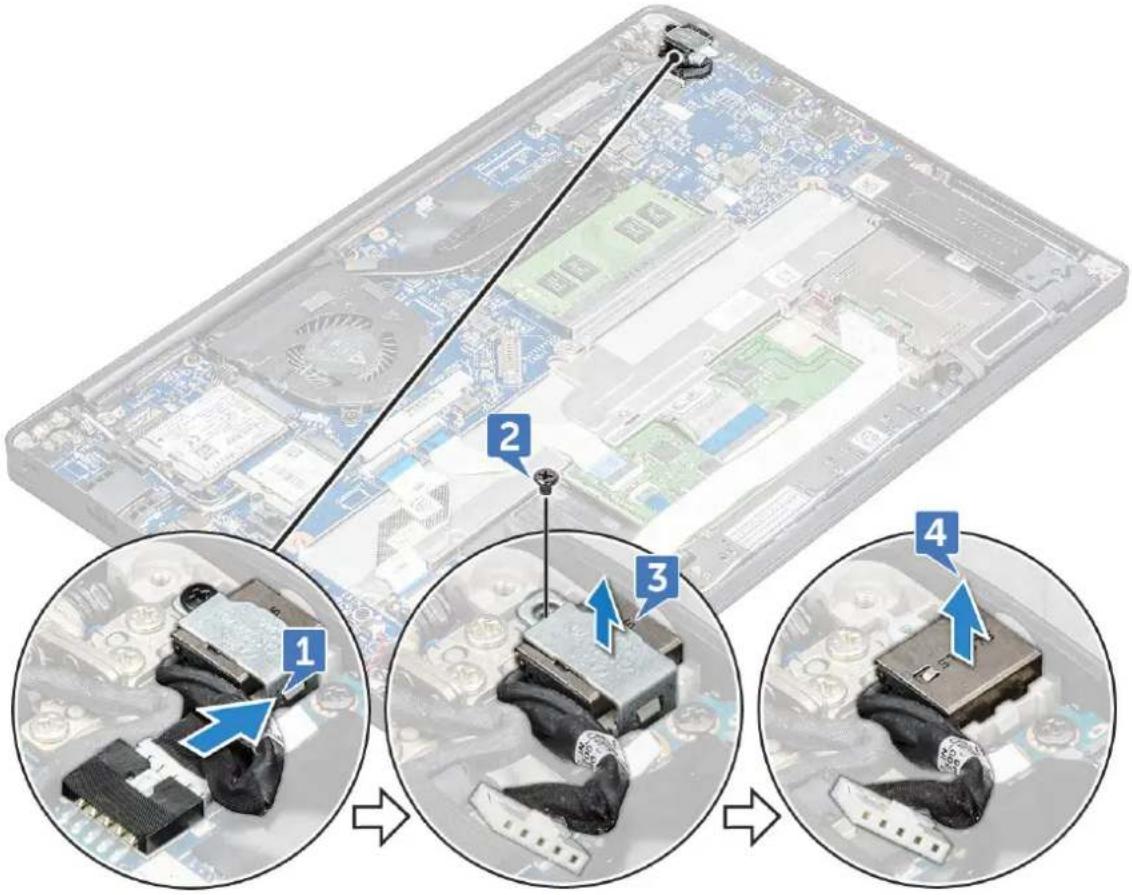
3 To remove the power connector port:
a Disconnect the power connector port cable from the system board [1].
NOTE: Use a plastic scribe to release the cable from the connector. Do not pull the cable as it may result in breakage
b Remove the M2.0x3.0 screw to release the metal bracket on the power connector port [2].
c Lift the metal bracket from the computer [3].
d Lift the power connector port from the computer [4].
text_image
Diagram illustrating a device's cable connection with four numbered steps showing assembly and disassembly of components.Installing power connector port
1 Install the power connector port into the slot on the computer.
2 Place the metal bracket on the power connector port.
3 Tighten the M2.0x3.0 screw to secure the power connector port to the computer.
4 Connect the power connector port cable to the connector on the system board.
5 Install the base cover.
6 Follow the procedure in After working inside your computer.
LED board
Removing LED board
1 Follow the procedure in Before working inside your computer.
2 Remove the base cover.:
3 To remove the LED board:
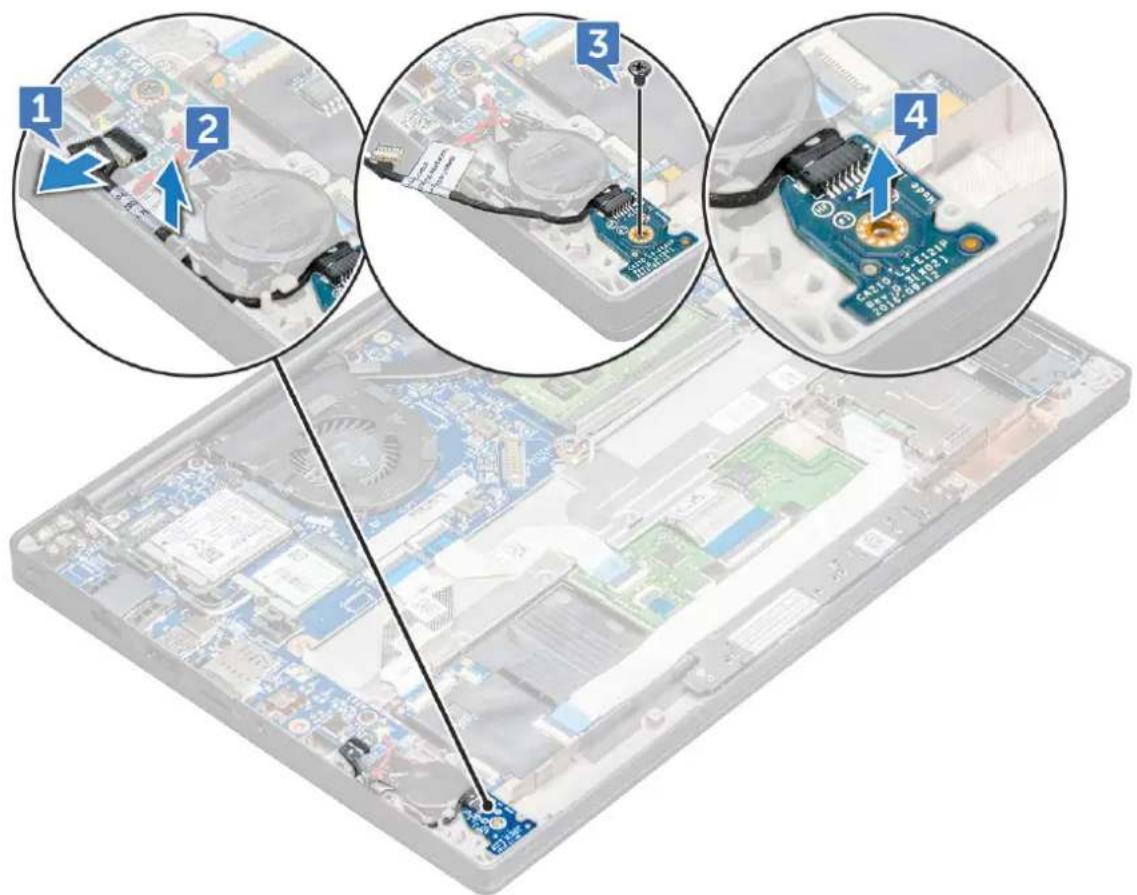
a Disconnect the LED cable from the LED board [1].
CAUTION: Avoid pulling the cable as it would result in breaking the cable connector. Instead, use a scribe to release the LED cable from its connector.
b Unroute the LED cable from the routing channel [2].
c Remove the M2.0 x 2.5 screw that secures the LED board to the computer [3] d Lift the LED board from the computer [4].
text_image
Diagram showing four steps of assembling a computer motherboard with labeled components and cable connectionsInstalling LED board
1 Insert the LED board into the slot on the computer.
2 Tighten the M2.0 x 2.5 screw to secure the LED board.
3 Route the LED cable through the routing channel.
4 Connect the LED cable to the LED board.
5 Install the base cover.
6 Follow the procedure in After working inside your computer.
Smart card module
Removing smart card cage
1 Follow the procedure in Before working inside your computer.
2 Remove the:
a base cover
b battery
c PCIe SSD card
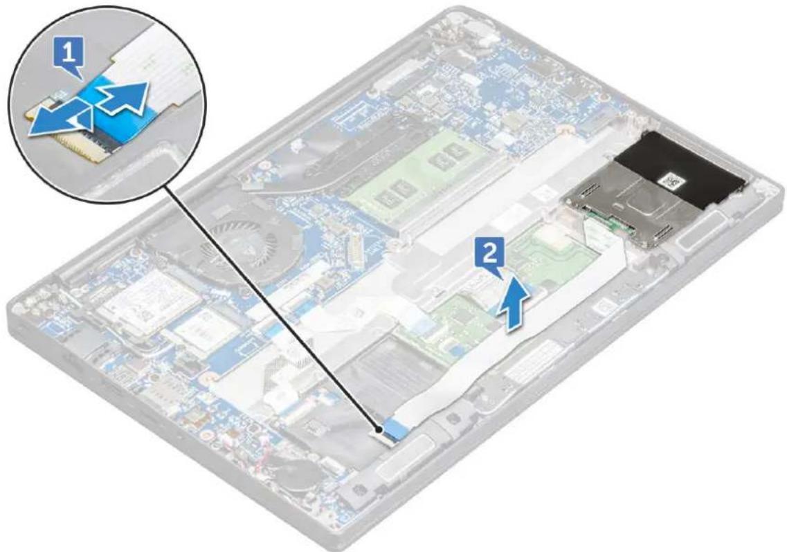
3 To disconnect the smart card cable:
a Disconnect the smart card cable [1].
b Lift the smart card cable that is affixed to the touchpad module [2].
text_image
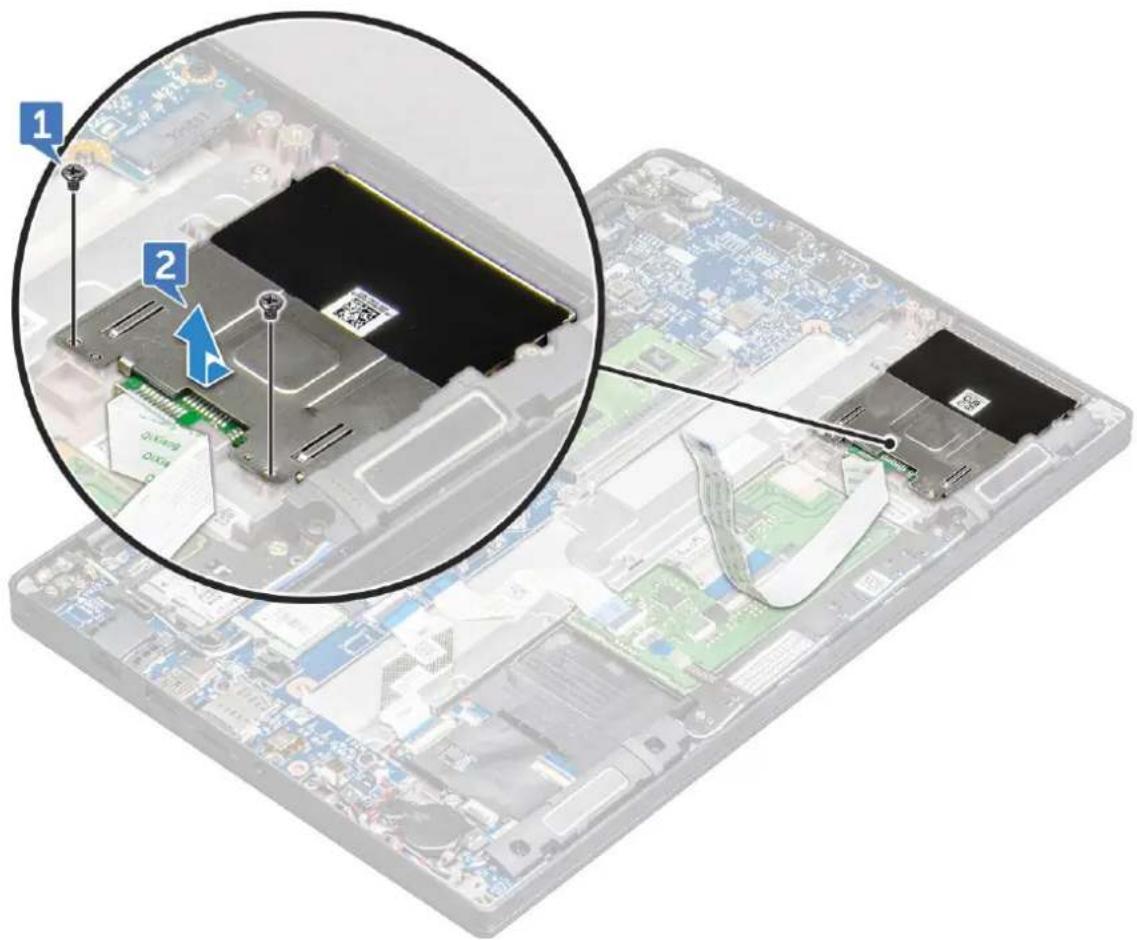
Diagram of an open computer case with labeled components and a magnified inset showing component 1 and component 2.4 To remove the smart card cage:
a Remove the M2.0 x 3.0 screws that secure the smart card cage to the computer [1]. b Slide and lift the smart card cage from the computer [2].
text_image
Diagram showing a computer motherboard with labeled components and a magnified inset highlighting a chip structure.Installing smart card cage
1 Slide the smart card cage into the slot to align with the tabs on the computer.
2 Tighten the M2.0 x 3.0 screws to secure the smart card cage to the computer.
3 Affix the smart card cable and connect it to the connector on the computer.
4 Install the:
a PCIe SSD card
b battery
c base cover
5 Follow the procedure in After working inside your computer.
Touchpad buttons board
Removing touchpad buttons board
1 Follow the procedure in Before working inside your computer.
2 Remove the:
a base cover
b battery
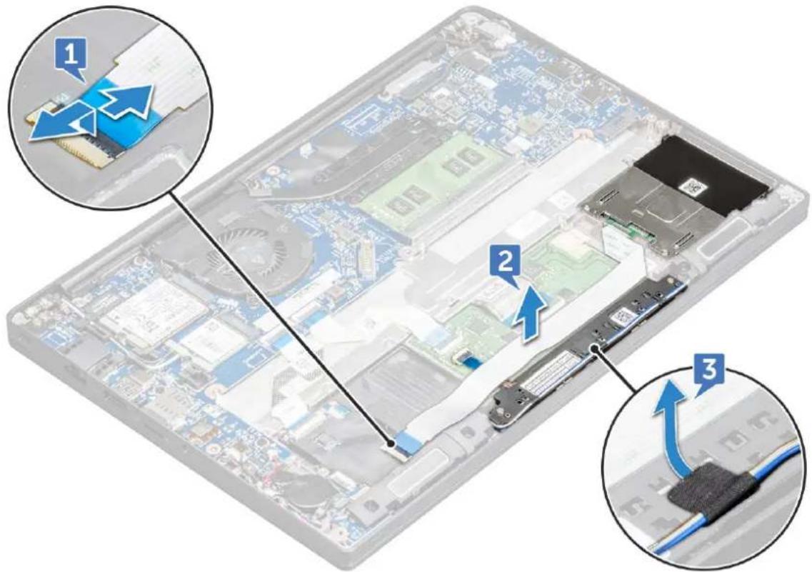
3 To disconnect the smart card cable:
a Disconnect the smart card cable [1].
b Lift the smart card cable that is affixed to the computer [2] to reveal the touchpad buttons board cable.
c Remove the adhesive tape that secures the speaker cable to the touchpad panel [3].
text_image
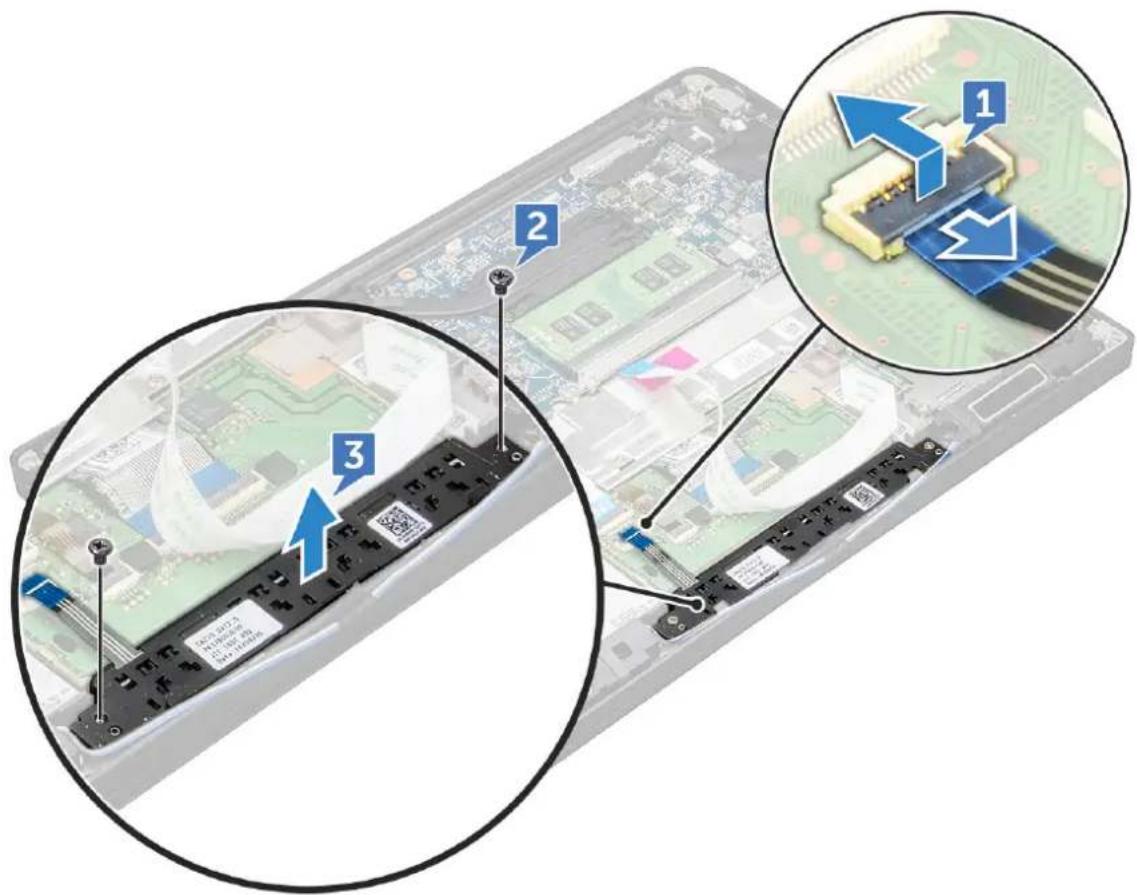
Diagram of an open computer case with labeled components and arrows indicating assembly or connection steps4 To remove the touchpad buttons board:
a Disconnect the touchpad buttons board cable from the touchpad board [1].
NOTE: The touchpad buttons board cable is below the smart card cable.
b Remove screws that secure the touchpad buttons board [2].
c Lift the touchpad buttons board from the computer [3].
text_image
Diagram showing three labeled components of a computer hardware module with annotations and arrows indicating assembly or installation steps.Installing touchpad buttons board
1 Insert the touchpad buttons board into the slot to align the tabs with the grooves on the computer.
2 Tighten the M2.0 x 2.5screws to secure the touchpad buttons board to the computer.
3 Connect the touchpad buttons board cable to the connector on the touchpad board.
4 Affix the smart card cable and connect it to the connector on the computer
5 Install the:
a speaker
b base cover
6 Follow the procedure in After working inside your computer.
Display Assembly
Removing display assembly
1 Follow the procedure in Before working inside your computer.
2 Remove the:
a base cover
b WLAN card
c WWAN card

NOTE: To identify the number of screws, see screw list
3 To remove the display assembly:
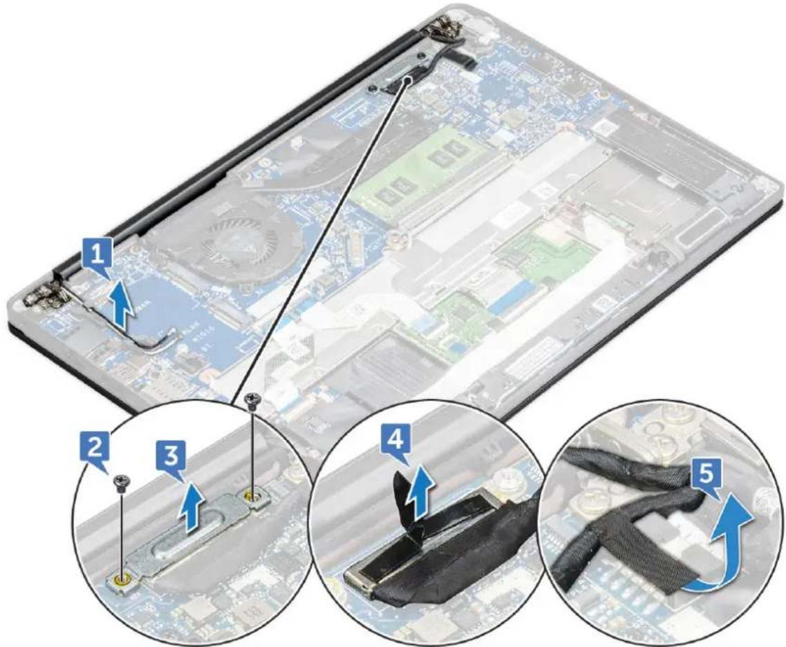
a Un route the WLAN and WWAN cables from the routing channels [1].
b Remove the M2.0 x 5.0 screws that secures the eDP bracket [2].
c Lift the eDP bracket from the eDP cable [3].
d Disconnect the eDP cable from its connector on the system board [4].
NOTE: In touch-configuration system, you need to remove the touch display cable connected to its connector on the system board.
e Remove the adhesive tape that secures the eDP cable [5].
NOTE: In touch-configuration system you will find both eDP cable and touch display cable secured with adhesive tape.
text_image
Diagram showing a disassembled electronic device with five labeled steps of cable or cable attachment, illustrating the process from disassembled components to final assembly.4 To remove the display assembly:
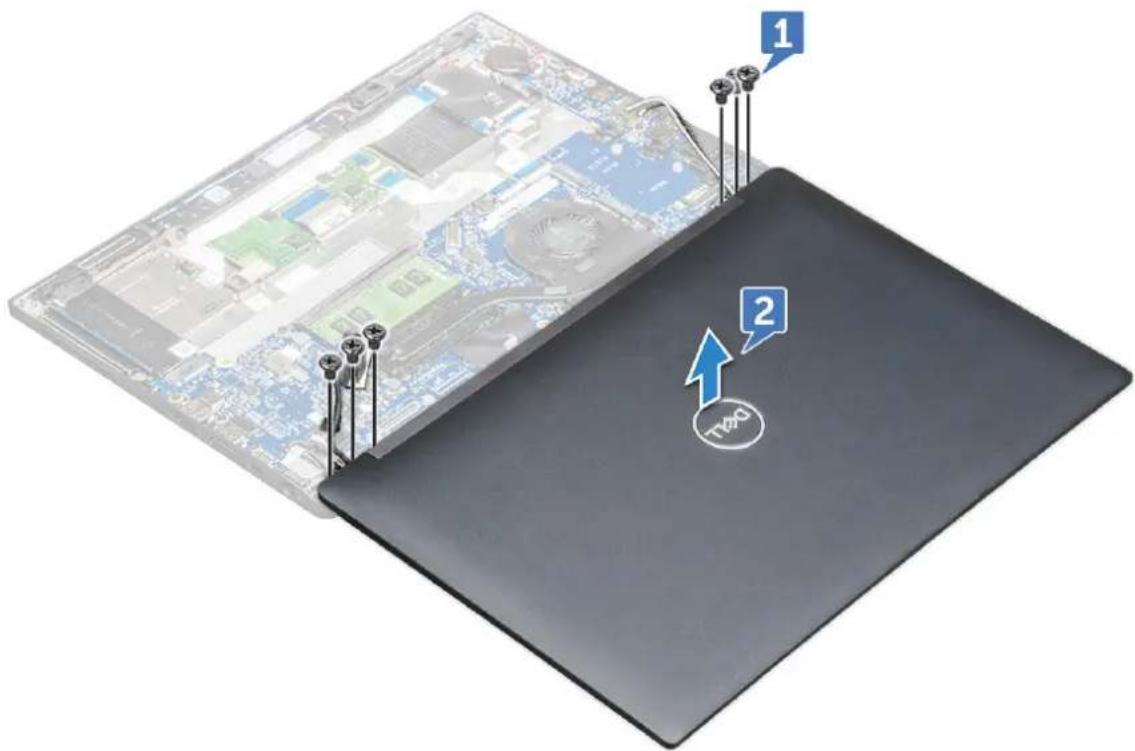
a Open the display of the computer and lay it on a flat surface at 180 degree angle
b Remove the M2.5 x 4.0 screws that secure the display hinge to the display assembly [1].
c Lift the display assembly from the computer.
text_image
1 2 N20Installing display assembly
1 Place the base of the computer on a plane surface of a table and position it closer to the edge of the table.
2 Install the display assembly to align it with the display hinge holders on the system.
3 Holding the display assembly, tighten the M2.5 x 4.0 screws to secure the display hinges on the system display assembly with the system unit.
4 Affix the tapes to secure the eDP cable (display cable).
For touch-configuration system you will see touch display cable, secure it with tapes along with the eDP cable.
5 Connect the eDP cable to the connector on the system board.

NOTE: For touch-configuration system, connect the touch display cable to its connector on the system board.
6 Install the eDP metal bracket on the eDP cable and tighten the M2.0 x 5.0 screws.
7 Route the WLAN and WWAN cables through the routing channels.
8 Install the:
a WLAN card
b WWAN card
c base cover
9 Follow the procedure in After working inside your computer.
Display hinge cap
Removing display hinge Cap
1 Follow the procedure in Before working inside your computer.
2 Remove the:
a base cover
b WLAN card
c WWAN card
d display assembly
NOTE: To identify the number of screws, see screw list
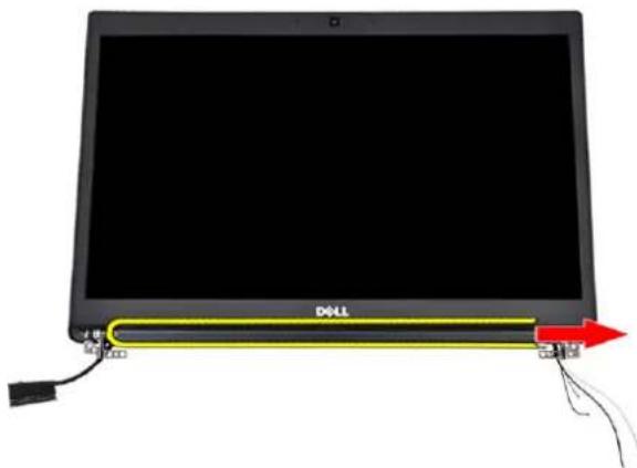
3 Push the display hinge cap to the right.
text_image
DOLL 20000000000000000000000000000000000000000000000000000000000000000000000000000000000000000000004 Remove the display hinge cap.

natural_image
Illustration of a laptop with a red upward arrow and cable connectors, no text or symbols present.Installing display hinge Cap
1 Insert the display hinge cap to the display assembly.
2 Push the display hinge cap to the left to secure it.
3 Install the:
a display assembly
b WLAN card
c WWAN card
d base cover
4 Follow the procedure in After working inside your computer.
System board
Removing system board
1 Follow the procedure in Before working inside your computer.
1 If your computer is shipped with a WWAN card, then the removal of a blank SIM card tray is a requirement.
2 Remove the:
a SIM card
b dummy SIM card tray
c base cover
d battery
e memory module
f PCIe SSD
g WLAN card
h WWAN card
i heat sink assembly
2 To identify the screws, see screw list
3 Remove the M2.0 x 3.0 screw that secures the memory module bracket to the system board [1].
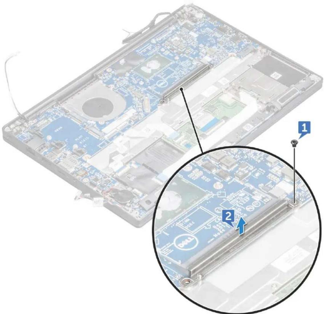
text_image
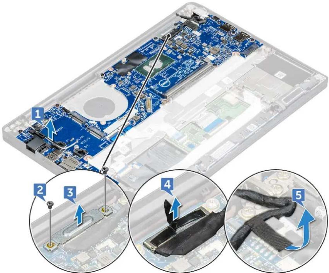
Laptop screen with visible circuit board and two zoomed-in views labeled 1 and 2, showing internal components and a Dell logo.4 To disconnect the eDP cable:

NOTE: If your system is shipped with an IR camera, then the IR cable must be disconnected. The IR cable is located beneath the eDP cable connector
a Un route the WLAN and WWAN cables from the routing channels [1].
b Remove the M2.0 x 3.0 screws that secure the eDP cable [2].
c Remove the eDP cable bracket [3].
d Disconnect the eDP cable from the system board [4].
e Lift the tape that secures the eDP cable to the system board [5].
text_image
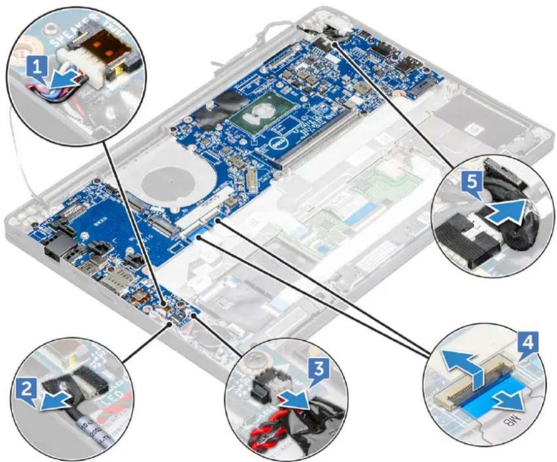
Labeled diagram of an electronic device showing internal components and assembly steps, with numbered annotations indicating key states.5 To disconnect the cables:
NOTE: To disconnect the speaker, LED board, coin cell battery and the power connector port cables, use a plastic scribe to release the cable from the connector. Do not pull the cable as it may result in breakage
a speaker cable [1]
b LED board cable [2]
c coin cell battery cable [3]
d touchpad cable and USH board cable [4]
e power connector port cable [5]
text_image
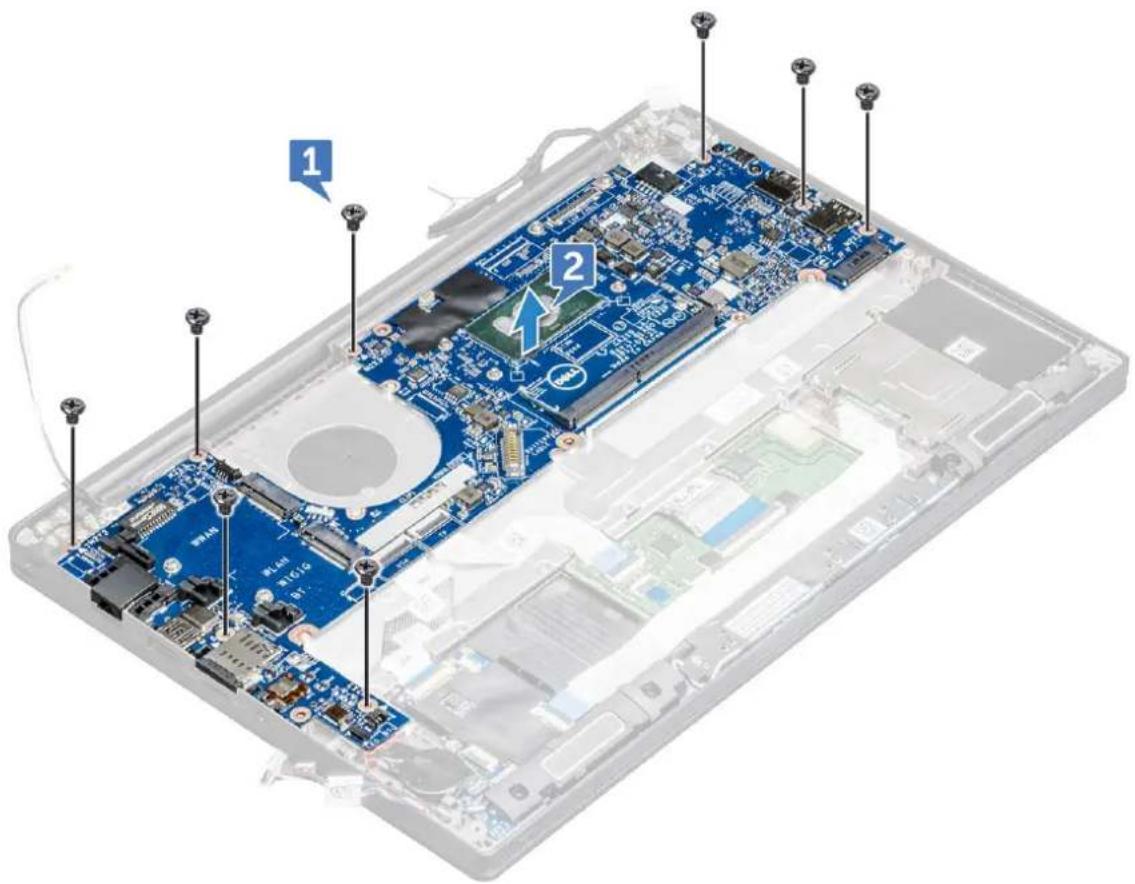
Labeled diagram of an electronic device showing internal components and parts with numbered annotations6 To remove the system board:
a Disconnect the M2.0x3.0 screws that secure the system board to computer [1].
NOTE: Refer system board screw list
b Lift the system board away from the computer.
text_image
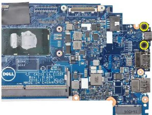
Labeled diagram of an open laptop motherboard showing internal components and parts with numbered annotations7 Remove the M2.0x5.0 screws that secure the USB Type-C bracket.
natural_image
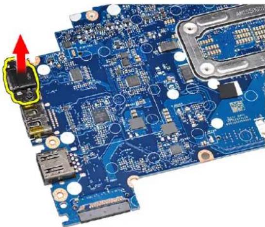
Close-up of a blue printed circuit board with visible components and connectors (no readable text or symbols)8 Flip the system board, peel off the tapes securing the bracket and remove the USB Type-C port from the system board.
natural_image
Close-up of a blue printed circuit board with visible components and a red arrow pointing to a component (no text or symbols)Installing system board
1 Align the system board with the screw holders on the computer.
2 Tighten the M2.0 x 5.0 screws to secure the system board to the computer.
3 Connect the speaker, power connector, LED board, touchpad, and USH cables to the connectors on the system board.
4 Connect the eDP cable to the connector on the system board.
5 Place the metal bracket over the eDP cable and tighten the M2.0 x 3.0screw to secure it.
6 Remove the metal bracket from the memory module connectors of the system board that was removed.
7 Place the metal bracket over the memory module connectors and tighten the M2.0 x 3.0 screws to secure it to the computer.
NOTE: If your computer has a WWAN card, then SIM card tray installation is a requirement.
8 Install the:
a heat sink
b WLAN card
c WWAN card
d SSD card
e memory module
f battery
g base cover
9 Follow the procedure in After working inside your computer.
Keyboard assembly
Removing keyboard assembly
NOTE: The keyboard and the keyboard tray together are called the keyboard assembly.
1 Follow the procedure in Before working inside your computer.
2 Remove:
a base cover
b battery
c memory module
d PCIe SSD
e WLAN card
f WWAN card
g heat sink assembly
h system board
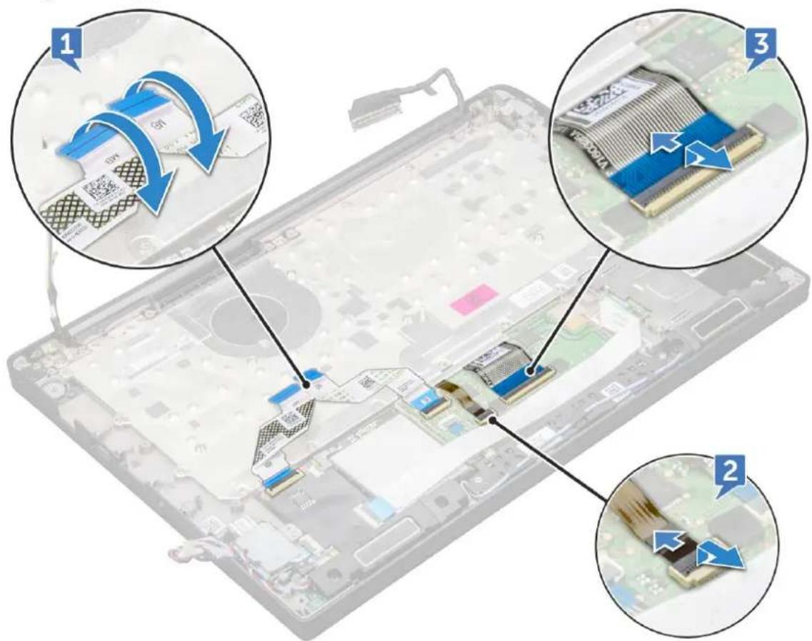
3 Disconnect the cables from the palmrest end:
a touchpad and USH board cables [1]
b keyboard backlight cable [2]
c keyboard cable [3]
text_image
Laptop screen with three annotated views showing internal components and QR code scanning process4 To remove the keyboard assembly:
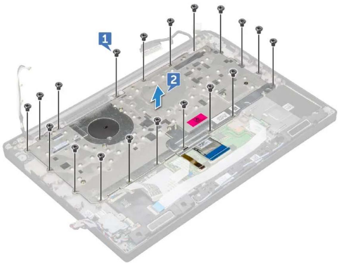
NOTE: To identify the screws, see screw list
a Remove the M2.0 x 2.5 screws that secure the keyboard [1].
b Lift the keyboard assembly from the chassis [2].
text_image
Laptop interior diagram with numbered annotations pointing to key componentsInstalling keyboard assembly
NOTE: The keyboard and the keyboard tray together are called the keyboard assembly.
1 Align the keyboard assembly with the screw holders on the computer.
2 Tighten the M2.0 x 2.5 screws that secure the keyboard to the chassis.
3 Connect the keyboard cable, keyboard backlight cable, touchpad cable and USH cable to the connectors on the touchpad buttons board.
4 Install the:
a system board
b heat sink
c WLAN card
d WWAN card
e SSD card
f memory module
g battery
h base cover
5 Follow the procedure in After working inside your computer.
Keyboard
Removing keyboard from keyboard tray
1 Follow the procedure in Before working inside your computer.
2 Remove the keyboard assembly
3 Remove the M2.0 x 2.0 screws that secure the keyboard to the keyboard assembly [1].
4 Lift the keyboard away from the keyboard tray [2].

text_image
Labeled diagram of a computer keyboard showing key keys and buttons with numbered annotationsInstalling keyboard to keyboard tray
1 Align the keyboard with the screw holders on the keyboard tray.
2 Tighten the M2.0 x 2.0 screws to secure the keyboard to the keyboard tray.
3 Install the keyboard assembly.
Palm rest
Replacing palm rest
1 Follow the procedure in Before working inside your computer.
2 Remove the:
a base cover
b battery
c memory module
d PCIe SSD
e WLAN card
f WWAN card
g power connector port
h heat sink assembly
i coin cell battery
j speaker
k display assembly
I system board
m keyboard
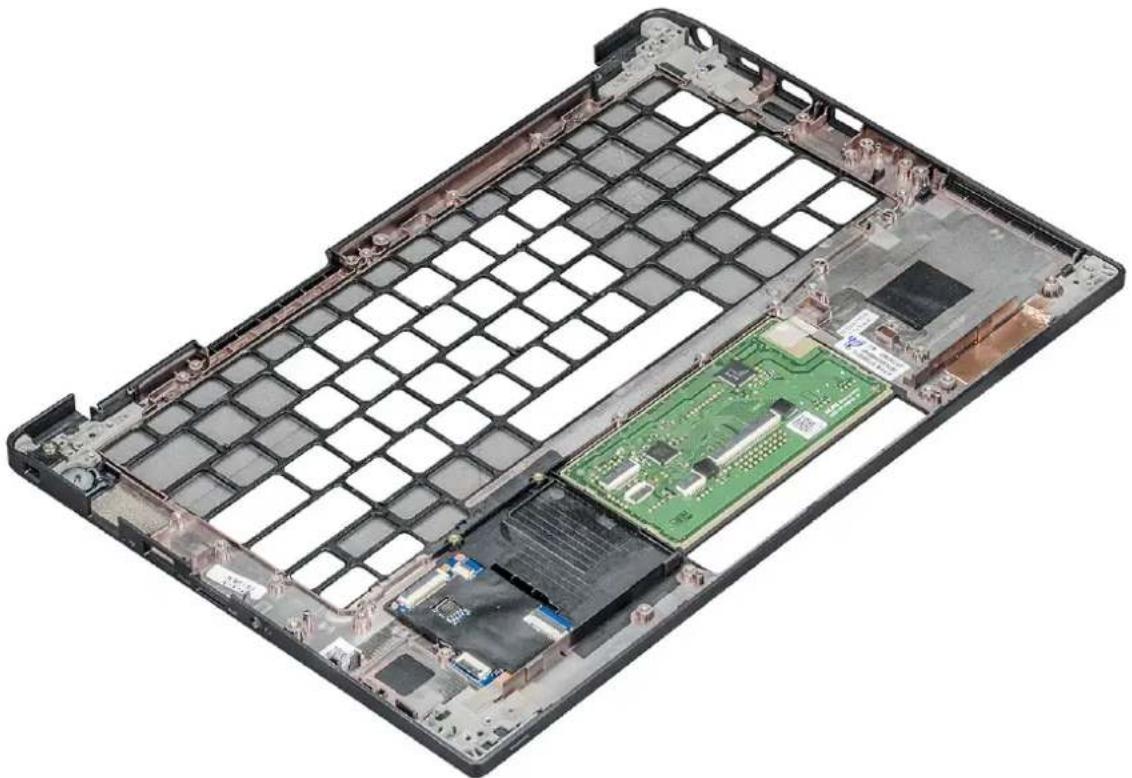
natural_image
Interior view of a computer chassis showing internal components like a green circuit board and grid partition (no text or symbols visible)The component you are left with is the palm rest.
3 Replace the palm rest.
4 Install the:
a keyboard
b system board
c display assembly
d speaker
e coin cell battery
f heatsink
g power connector port
h WLAN card
i WWAN card
j PCIe SSD
k memory
I battery
m base cover
5 Follow the procedure in After working inside your computer.
Technology and components
This chapter details the technology and components available in the system.
Topics:
- USB features
· HDMI 1.4
USB features
Universal Serial Bus, or USB, was introduced in 1996. It dramatically simplified the connection between host computers and peripheral devices like mice, keyboards, external drivers, and printers.
Let's take a quick look on the USB evolution referencing to the table below.
Table 2. USB evolution
Type Data Transfer Rate Category Introduction Year
USB 3.0/USB 3.1 Gen 2 5 Gbps Super Speed 2010
USB 2.0 480 Mbps High Speed 2000
USB 3.0/USB 3.1 Gen 1 (SuperSpeed USB)
For years, the USB 2.0 has been firmly entrenched as the de facto interface standard in the PC world with about 6 billion devices sold, and yet the need for more speed grows by ever faster computing hardware and ever greater bandwidth demands. The USB 3.0/USB 3.1 Gen 1 finally has the answer to the consumers' demands with a theoretically 10 times faster than its predecessor. In a nutshell, USB 3.1 Gen 1 features are as follows:
• Higher transfer rates (up to 5 Gbps)
- Increased maximum bus power and increased device current draw to better accommodate power-hungry devices
- New power management features
• Full-duplex data transfers and support for new transfer types
- Backward USB 2.0 compatibility
- New connectors and cable
The topics below cover some of the most commonly asked questions regarding USB 3.0/USB 3.1 Gen 1.

Speed
Currently, there are 3 speed modes defined by the latest USB 3.0/USB 3.1 Gen 1 specification. They are Super-Speed, Hi-Speed and Full-Speed. The new SuperSpeed mode has a transfer rate of 4.8Gbps. While the specification retains Hi-Speed, and Full-Speed USB mode,
commonly known as USB 2.0 and 1.1 respectively, the slower modes still operate at 480Mbps and 12Mbps respectively and are kept to maintain backward compatibility.
USB 3.0/USB 3.1 Gen 1 achieves the much higher performance by the technical changes below:
- An additional physical bus that is added in parallel with the existing USB 2.0 bus (refer to the picture below).
- USB 2.0 previously had four wires (power, ground, and a pair for differential data); USB 3.0/USB 3.1 Gen 1 adds four more for two pairs of differential signals (receive and transmit) for a combined total of eight connections in the connectors and cabling.
- USB 3.0/USB 3.1 Gen 1 utilizes the bidirectional data interface, rather than USB 2.0's half-duplex arrangement. This gives a 10-fold increase in theoretical bandwidth.
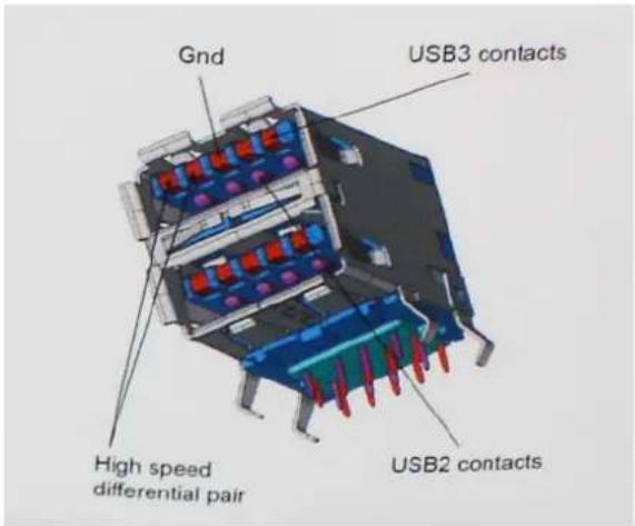
text_image
Gnd USB3 contacts High speed differential pair USB2 contactsWith today's ever increasing demands placed on data transfers with high-definition video content, terabyte storage devices, high megapixel count digital cameras etc., USB 2.0 may not be fast enough. Furthermore, no USB 2.0 connection could ever come close to the 480Mbps theoretical maximum throughput, making data transfer at around 320Mbps (40MB/s) — the actual real-world maximum. Similarly, USB 3.0/USB 3.1 Gen 1 connections will never achieve 4.8Gbps. We will likely see a real-world maximum rate of 400MB/s with overheads. At this speed, USB 3.0/USB 3.1 Gen 1 is a 10x improvement over USB 2.0.
Applications
USB 3.0/USB 3.1 Gen 1 opens up the laneways and provides more headroom for devices to deliver a better overall experience. Where USB video was barely tolerable previously (both from a maximum resolution, latency, and video compression perspective), it's easy to imagine that with 5-10 times the bandwidth available, USB video solutions should work that much better. Single-link DVI requires almost 2Gbps throughput. Where 480Mbps was limiting, 5Gbps is more than promising. With its promised 4.8Gbps speed, the standard will find its way into some products that previously weren't USB territory, like external RAID storage systems.
Listed below are some of the available SuperSpeed USB 3.0/USB 3.1 Gen 1 products:
• External Desktop USB 3.0/USB 3.1 Gen 1 Hard Drives
- Portable USB 3.0/USB 3.1 Gen 1 Hard Drives
• USB 3.0/USB 3.1 Gen 1 Drive Docks & Adapters
- USB 3.0/USB 3.1 Gen 1 Flash Drives & Readers
• USB 3.0/USB 3.1 Gen 1 Solid-state Drives
• USB 3.0/USB 3.1 Gen 1 RAIDs
• Optical Media Drives
- Multimedia Devices
- Networking
• USB 3.0/USB 3.1 Gen 1 Adapter Cards & Hubs
Compatibility
The good news is that USB 3.0/USB 3.1 Gen 1 has been carefully planned from the start to peacefully co-exist with USB 2.0. First of all, while USB 3.0/USB 3.1 Gen 1 specifies new physical connections and thus new cables to take advantage of the higher speed capability of the new protocol, the connector itself remains the same rectangular shape with the four USB 2.0 contacts in the exact same location as before. Five new connections to carry receive and transmitted data independently are present on USB 3.0/USB 3.1 Gen 1 cables and only come into contact when connected to a proper SuperSpeed USB connection.
Windows 8/10 will be bringing native support for USB 3.1 Gen 1 controllers. This is in contrast to previous versions of Windows, which continue to require separate drivers for USB 3.0/USB 3.1 Gen 1 controllers.
Microsoft announced that Windows 7 would have USB 3.1 Gen 1 support, perhaps not on its immediate release, but in a subsequent Service Pack or update. It is not out of the question to think that following a successful release of USB 3.0/USB 3.1 Gen 1 support in Windows 7, SuperSpeed support would trickle down to Vista. Microsoft has confirmed this by stating that most of their partners share the opinion that Vista should also support USB 3.0/USB 3.1 Gen 1.
Super-Speed support for Windows XP is unknown at this point. Given that XP is a seven-year-old operating system, the likelihood of this happening is remote.
Thunderbolt over Type-C
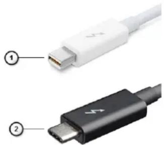
Thunderbolt is a hardware interface that combines data, video, audio, and power in a single connection. Thunderbolt combines PCI Express (PCIe) and DisplayPort (DP) into one serial signal, and additionally provides DC power, all in one cable. Thunderbolt 1 and Thunderbolt 2 use the same connector as miniDP (DisplayPort) to connect to peripherals, while Thunderbolt 3 uses a USB Type-C connector.
natural_image
Two types of USB connectors shown: one white with a USB cable and one black with a plug (no text or symbols visible)Figure 1. Thunderbolt 1 and Thunderbolt 3
1 Thunderbolt 1 and Thunderbolt 2 (using a miniDP connector)
2 Thunderbolt 3 (using a USB Type-C connector)
Thunderbolt 3 over Type-C
Thunderbolt 3 brings Thunderbolt to USB Type-C at speeds up to 40 Gbps, creating one compact port that does it all - delivering the fastest, most versatile connection to any dock, display or data device like an external hard drive. Thunderbolt 3 uses a USB Type-C connector/port to connect to supported peripherals.
1 Thunderbolt 3 uses USB Type-C connector and cables - It is compact and reversible
2 Thunderbolt 3 supports speed up to 40 Gbps
3 DisplayPort 1.2 - compatible with existing DisplayPort monitors, devices and cables
4 USB Power Delivery - Up to 130W on supported computers
Key Features of Thunderbolt 3 over USB Type-C
1 Thunderbolt, USB, DisplayPort and power on USB Type-C on a single cable (features vary between different products)
2 USB Type-C connector and cables which are compact and reversible
3 Supports Thunderbolt Networking (*varies between different products)
4 Supports up to 4K displays
5 Up to 40 Gbps
NOTE: Data transfer speed may vary between different devices.
Thunderbolt Icons
| Protocol | USB Type-A | USB Type-C | Notes |
| Thunderbolt | Not Applicable | Will use industry standard icon regardless of port style (i.e., mDP or USB Type-C) | |
| Thunderbolt w/ Power Delivery | Not Applicable | Up to 130 Watts via USB Type-C |
Figure 2. Thunderbolt Iconography Variations
Advantages of Displayport over USB Type-C
• Full DisplayPort audio/video (A/V) performance (up to 8K at 60Hz)
• SuperSpeed USB (USB 3.1) data
- Reversible plug orientation and cable direction
- Backwards compatibility to VGA, DVI with adaptors
• Supports HDMI 2.0a and is backwards compatible with previous versions
HDMI 1.4
This topic explains the HDMI 1.4 and its features along with the advantages.
HDMI (High-Definition Multimedia Interface) is an industry-supported, uncompressed, all-digital audio/video interface. HDMI provides an interface between any compatible digital audio/video source, such as a DVD player, or A/V receiver and a compatible digital audio and/or video monitor, such as a digital TV (DTV). The intended applications for HDMI TVs, and DVD players. The primary advantage is cable reduction and content protection provisions. HDMI supports standard, enhanced, or high-definition video, plus multichannel digital audio on a single cable.
NOTE: The HDMI 1.4 will provide 5.1 channel audio support.
HDMI 1.4 Features
- HDMI Ethernet Channel - Adds high-speed networking to an HDMI link, allowing users to take full advantage of their IP-enabled devices without a separate Ethernet cable
-
Audio Return Channel - Allows an HDMI-connected TV with a built-in tuner to send audio data "upstream" to a surround audio system, eliminating the need for a separate audio cable
• 3D - Defines input/output protocols for major 3D video formats, paving the way for true 3D gaming and 3D home theater applications -
Content Type - Real-time signaling of content types between display and source devices, enabling a TV to optimize picture settings based on content type
• Additional Color Spaces - Adds support for additional color models used in digital photography and computer graphics - 4 K Support - Enables video resolutions far beyond 1080p, supporting next-generation displays that will rival the Digital Cinema systems used in many commercial movie theaters
• HDMI Micro Connector - A new, smaller connector for phones and other portable devices, supporting video resolutions up to 1080p
• Automotive Connection System - New cables and connectors for automotive video systems, designed to meet the unique demands of the motoring environment while delivering true HD quality
Advantages of HDMI
• Quality HDMI transfers uncompressed digital audio and video for the highest, crispest image quality.
- Low -cost HDMI provides the quality and functionality of a digital interface while also supporting uncompressed video formats in a simple, cost-effective manner
- Audio HDMI supports multiple audio formats from standard stereo to multichannel surround sound
- HDMI combines video and multichannel audio into a single cable, eliminating the cost, complexity, and confusion of multiple cables currently used in A/V systems
- HDMI supports communication between the video source (such as a DVD player) and the DTV, enabling new functionality
This chapter details the supported operating systems along with instructions on how to install the drivers.
Topics:
• Supported operating systems
- Downloading drivers
Supported operating systems
Table 3. Operating systems
| Windows | · Microsoft Windows 10 Pro 64 bit |
| · Microsoft Windows 10 Home 64 bit | |
| · Microsoft Windows 7 Professional 32/64 bit, (available through downgrade rights from Windows10 Pro License) (available with Intel 6th Gen Core I processors only) | |
| · Microsoft Windows 8.1 Professional 64 bit, (available through downgrade rights from Windows 10 Pro License only through Dell Configuration Services) (Available with Intel 6thGen Core I only) | |
| Other | · Ubuntu 16.04 LTS SP1 64 bit |
| · NeoKylin v6.0 64 bit | |
| OS media support | · Dell.com/support to download eligible Windows OS |
| · USB media available as upsell |
Downloading drivers
1 Turn on the tablet.
2 Go to Dell.com/support.
3 Click Product Support, enter the Service Tag of your tablet, and then click Submit.

NOTE: If you do not have the Service Tag, use the auto detect feature or manually browse for your tablet model.
4 Click Drivers and Downloads.
5 Select the operating system installed on your tablet.
6 Scroll down the page and select the driver to install.
7 Click Download File to download the driver for your tablet.
8 After the download is complete, navigate to the folder where you saved the driver file.
9 Double-click the driver file icon and follow the instructions on the screen.
Chipset driver
The chipset driver helps the system identify the components and install necessary drivers accurately. Verify that the chipset was installed in the system by checking the below controllers. Many of the common devices are visible under Other Devices if no drivers are installed. The unknown devices disappear once you install the chipset driver.
Make sure to install the following drivers, some of them may exist by default.
- Intel HID Event Filter Driver
• Intel Dynamic Platform and Thermal Framework Driver - Intel serial IO driver
• Intel Thunderbolt(TM) Controller driver - Management Engine
• Realtek PCI-E memory card
Realtek PCIE drivers
Verify if the Realtek PCIe drivers are already installed in the computer.

Memory technology devices

Realtek PCIE CardReader
Management Engine Interface
Verify if the Intel Management Engine Interface drivers are already installed in the computer.
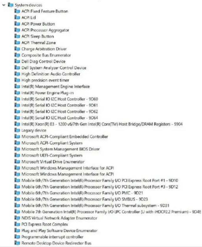
text_image
System devices ACPI Fixed Feature Button ACPI Lid ACPI Power Button ACPI Processor Aggregator ACPI Sleep Button ACPI Thermal Zone Charge Arbitration Driver Composite Bus Enumerator Dell Diag Control Device Dell System Analyzer Control Device High Definition Audio Controller High precision event timer Intel(R) Management Engine Interface Intel(R) Power Engine Plug-in Intel(R) Serial IO I2C Host Controller - 9D60 Intel(R) Serial IO I2C Host Controller - 9D61 Intel(R) Serial IO I2C Host Controller - 9D62 Intel(R) Serial IO I2C Host Controller - 9D64 Intel(R) Xeon(R) E3 - 1200 v6/7th Gen Intel(R) Core(TM) Host Bridge/DRAM Registers - 5904 Legacy device Microsoft ACPI-Compliant Embedded Controller Microsoft ACPI-Compliant System Microsoft System Management BIOS Driver Microsoft UEFI-Compliant System Microsoft Virtual Drive Enumerator Microsoft Windows Management Interface for ACPI Microsoft Windows Management Interface for ACPI Mobile 6th/7th Generation Intel(R) Processor Family I/O PCI Express Root Port #1 - 9D10 Mobile 6th/7th Generation Intel(R) Processor Family I/O PCI Express Root Port #3 - 9D12 Mobile 6th/7th Generation Intel(R) Processor Family I/O PMC - 9D21 Mobile 6th/7th Generation Intel(R) Processor Family I/O SMBUS - 9D23 Mobile 6th/7th Generation Intel(R) Processor Family I/O Thermal subsystem - 9D31 Mobile 7th Generation Intel(R) Processor Family I/O UPC Controller (U with iHDCP2.2 Premium) - 9D4E NDIS Virtual Network Adapter Enumerator PCI Express Root Complex Plug and Play Software Device Enumerator Programmable interrupt controller Remote Desktop Device Redirector BusManagement Engine Interface drivers

Intel(R) Dynamic Platform and Thermal Framework
Intel(R) Dynamic Platform and Thermal Framework Generic Participant
Intel(R) Dynamic Platform and Thermal Framework Generic Participant
Intel(R) Dynamic Platform and Thermal Framework Generic Participant
Intel(R) Dynamic Platform and Thermal Framework Manager
Intel(R) Dynamic Platform and Thermal Framework Processor Participant
Serial IO driver
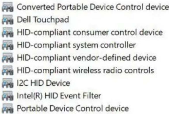
Verify if the drivers for Touchpad, IR camera, and keyboard and are installed.


Human Interface Devices
text_image
Converted Portable Device Control device Dell Touchpad HID-compliant consumer control device HID-compliant system controller HID-compliant vendor-defined device HID-compliant wireless radio controls I2C HID Device Intel(R) HID Event Filter Portable Device Control device
Keyboards
HID Keyboard Device
HID Keyboard Device
HID Keyboard Device
Standard PS/2 Keyboard
Figure 3. Serial IO driver
Graphics controller driver
Verify if the graphics controller driver is already installed in the computer.
Table 4. Graphics controller driver
Before Installation After Installation


Display adapters

Microsoft Basic Display Adapter

Display adapters

Intel(R) HD Graphics 620
USB drivers
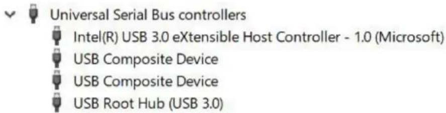
Verify if the USB drivers are already installed in the computer.

text_image
Universal Serial Bus controllers Intel(R) USB 3.0 eXtensible Host Controller - 1.0 (Microsoft) USB Composite Device USB Composite Device USB Root Hub (USB 3.0)Network drivers
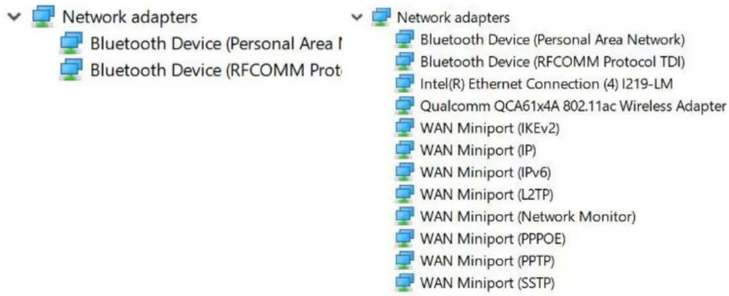
Install the WLAN and Bluetooth drivers from the Dell support site.
Table 5. Network drivers
Before installation After installation
text_image
Network adapters Bluetooth Device (Personal Area I Bluetooth Device (RFCOMM Prot Network adapters Bluetooth Device (Personal Area Network) Bluetooth Device (RFCOMM Protocol TDI) Intel(R) Ethernet Connection (4) I219-LM Qualcomm QCA61x4A 802.11ac Wireless Adapter WAN Miniport (IKEv2) WAN Miniport (IP) WAN Miniport (IPv6) WAN Miniport (L2TP) WAN Miniport (Network Monitor) WAN Miniport (PPPOE) WAN Miniport (PPTP) WAN Miniport (SSTP)Realtek Audio
Verify if audio drivers are already installed in the computer.
Table 6. Realtek audio
Before Installation After Installation

text_image
Sound, video and game controllers Intel(R) Display Audio Sound, video and game controllers Intel(R) Display Audio Realtek AudioSerial ATA drivers
Install the latest Intel Rapid Storage driver for best performance. Using the default Windows storage drivers is not recommended. Verify if the default serial ATA drivers are installed in the computer.


Storage controllers

Intel Chipset SATA RAID Controller

Microsoft Storage Spaces Controller
Security drivers
This section lists the security devices in the Device Manager.
Security device drivers
Verify if the security device drivers are installed in the computer.


Security devices

Trusted Platform Module 2.0
Fingerprint sensor drivers


ControlVault Device

Dell ControlVault w/o Fingerprint Sensor
Verify if the Fingerprint sensor drivers are installed in the computer.
System specifications

NOTE: Offerings may vary by region. The following specifications are only those required by law to ship with your computer. For more information about the configuration of your computer, go to Help and Support in your Windows operating system and select the option to view information about your computer.
Topics:
- Processor specifications
- System specifications
- Memory specifications
• Video specifications
• Audio specifications - Battery specifications
- AC adapter specifications
- Port and connector specifications
• Communication specifications - Touchpad specifications
- Camera specifications
- Display
- Dimensions and Weight
• Environmental specifications
Processor specifications
Feature
Specification
Types
- 7th generation Intel Core i3 / i5 / i7 series
• 6th generation Intel Core i5 / i7 series
System specifications
Feature
Specification
Chipset Integrated in the processor
DRAM bus width 64-bit
Flash EPROM SPI 128 Mbits
PCIe bus 100 MHz
External Bus
DMI 3.0—8GT/s
Frequency
Memory specifications
Feature Specification
Memory connector One SO-DIMM slot
Memory type DDR4 SDRAM—2133 MHz
Minimum memory 4 GB
Maximum memory 16 GB
Video specifications
Feature Specification
Type Integrated on system board
UMA controller
• Intel Integrated HD Graphics 620
- Intel Integrated HD Graphics 520 (available with Intel 6th Gen Core I only)
External display support
- On system – eDP (internal display), HDMI
- Optional Type-C port – VGA, DisplayPort 1.2, DVI and optional Thunderbolt 3
NOTE: Supports one VGA, DisplayPort, HDMI through the docking station connected to optional Thunderbolt 3 controller.
Audio specifications
Feature Specification
Types Four-channel high-definition audio
Controller Realtek ALC3246
Stereo conversion 24-bit—analog-to-digital and digital-to-analog
Internal interface High-definition audio
External interface Microphone-in, stereo headphones, and headset combo connector
Speakers Two
Internal speaker amplifier 2 W (RMS) per channel
Volume controls Hot keys
Battery specifications
Feature Specification
Type
• 3-cell Lithium Prismatic battery with ExpressCharge
• 4-cell Lithium Prismatic battery with ExpressCharge
42 WHr (3-cell):
Feature Specification
Length 200.5 mm (7.89 inches)
Width 95.9 mm (3.78 inches)
Height 5.7 mm (0.22 inch)
Weight 185.0 g (0.41 lb)
Voltage 11.4 VDC
60 WHr (4-cell):
Length 238 mm (9.37 inches)
Width 95.9 mm (3.78 inch)
Height 5.7 mm (0.22 inch)
Weight 270 g (0.6 lb)
Voltage 7.6 VDC
Life span 300 discharge per charge cycles
Temperature range
Operating
- Charge: 0°C to 50°C (32°F to 158°F)
- Discharge: 0°C to 70°C (32°F to 122°F)
Non-operating - 20°C to 65°C (- 4°F to 149°F)
Coin cell battery 3 V CR2032 lithium coin cell
AC adapter specifications
Feature Specification
Type 65 W or 90 W
NOTE: The system is shipped with 65 W adapter and also supports 90 W adapter for fast charging.
Input voltage 100 V AC to 240 V AC
Input current— 1.7 A / 2.5 A
maximum
Input frequency 50 Hz to 60 Hz
Output current 3.34 A and 4.62 A
Rated output 19.5 V DC
voltage
Weight 230 g (65 W) and 320 g (90 W)
Dimensions 22 x 66 x 106 mm (65 W) and 22 x 66 x 130 (90 W)
Temperature range 0°C to 40°C (32°F to 104°F)
—Operating
Temperature range -40^ to 70^ ( -40^ to 158^ )
—Non-Operating
Port and connector specifications
Feature Specification
Audio Microphone-in, stereo headphones, and headset combo connector
Video HDMI 1.4
Network adapter One RJ-45 connector
USB
- Two USB 3.1 Gen1 ports - one PowerShare capable
- Type-C USB 3.1 Display port (optional Thunderbolt 3 controller)
Memory card reader one Micro SD 4.0
Micro Subscriber One
Identity Module
(uSIM) card
Docking port None
NOTE: Cable docking - USB type-C docking.
Express Card None
AC adapter One
Smart card reader One (optional)
Communication specifications
Features Specification
Network adapter 10/100/1000 Mb/s Ethernet (RJ-45)
Wireless Internal wireless local area network (WLAN), wireless wide area network (WWAN), WiGig
Touchpad specifications
Feature Specification
Active Area:
X-axis 99.50 mm
Y-axis 53.0 mm
X/Y position X: 1048cpi; Y:984cpi
resolution
Multi-touch Configurable single finger and multi-finger gestures
Camera specifications
Easy Remote Collaboration:
• Video conference online with an optional built-in camera
- Windows Hello feature can be enabled with IR Camera embedded
Table 7. Camera specifications
Camera features 13 HD/FHD 13" FHD 13" FHD touch
| Camera Type | HD fixed focus | HD fixed focus | HD fixed focus |
| IR Camera N/A Yes N/A | |||
| Sensor Type CMOS sensor technology CMOS sensor | technology | CMOS sensor technology | |
| Resolution: Motion Video Up to 1280x720 (0.92MP) Up to 1280x720 | (0.92MP) | Up to 1280x720 (0.92MP) | |
| Resolution: Still Image | Up to 1280 x 720 (0.92MP) | Up to 1280 x 720 (0.92MP) | Up to 1280 x 720 (0.92MP) |
| Imaging Rate | Up to 30 frames per second | Up to 30 frames per second | Up to 30 frames per second |
Display
Table 8. 13.3" (16:9) AG FHD WLED 300 nits eDP 1.3 WVA
| Feature | Specification |
| Type | FHD Anti-Glare |
| Luminance (typical) | 300 nits |
| Dimensions (Active Area) | • Height: 165.24 mm• Width: 293.47 mm• Diagonal: 13.3 inch |
| Native Resolution | 1920 x 1080 |
| Megapixels | 2.07 |
| Pixels per Inch (PPI) | 166 |
| Contrast Ratio (min) | 800:1 |
| Response Time (max) | 35 msec rise/fall |
| Refresh Rate | 60 Hz |
| Horizontal View Angle | +/- 80 degrees |
| Vertical View Angle | +/- 80 degrees |
| Pixel Pitch | 0.153 mm |
| Power Consumption (maximum) | 4.6 W |
Table 9. 13.3" (16:9) AG FHD Touch WLED 300 nits eDP 1.3 WVA
| Feature | Specification |
| Type | FHD Anti-Smudge |
| Luminance (typical) | 300 nits |
| Dimensions (Active Area) | • Height:165.24 mm• Width: 293.47 mm |
Native Resolution 1920 x 1080
Megapixels 2.07
Pixels per Inch (PPI) 166
Contrast Ratio (min) 800:1
Response Time (max) 35msec rise/fall
Refresh Rate 60 Hz
Horizontal View Angle +/- 80 degrees
Vertical View Angle +/- 80 degrees
Pixel Pitch 0.153 mm
Power Consumption (maximum) 5.2 W
Dimensions and Weight
Table 10. Dimensions
Dimensions Inches Millimeter
| Width 12.00 | 304.80 | |
| Depth | 8.19 | 207.95 |
| Height (front, full) for NT FHD and Touch FHD | 0.657 | 16.7 |
| Height (front, full) for NT Thin Bezel FHD) | 0.67 | 16.95 |
| Height (front) for NT FHD and Touch FHD | 0.44 | 11.16 |
| Height (front) for NT Thin Bezel FHD | 0.45 | 11.41 |
| Height (rear, full) for all configurations | 0.785 | 19.95 |
| Height (rear) for all configurations | 0.55 | 13.95 |
Table 11. Weight
| Starting weight | Pounds Kilograms | |
| 2.59 | 1.17 |
Environmental specifications
Temperature Specifications
Operating 0°C to 60°C (32°F to 140°F)
Storage -51°C to 71°C (-59°F to 159°F)
Relative humidity Specifications
—maximum
Operating 10% to 90% (non-condensing)
Storage 5% to 95% (non-condensing)
Altitude— Specifications
maximum
Operating -15.2 m to 3048 m (-50 to 10,000 ft)
0^ C to 35^ C
Non-operating -15.24 m to 10,668 m (-50 ft to 35,000 ft)
Airborne G2 or lower as defined by ISA S71.04–1985
contaminant level
System setup
System setup enables you to manage your tablet hardware and specify BIOS level options. From the System setup, you can:
- Change the NVRAM settings after you add or remove hardware
• View the system hardware configuration - Enable or disable integrated devices
- Set performance and power management thresholds
- Manage your computer security
Topics:
- Boot menu
- Navigation keys
- System setup options
- General screen options
- System Configuration screen options
• Video screen options
• Security screen options - Secure Boot screen options
• Intel Software Guard Extensions screen options
• Performance screen options
• Power Management screen options - POST Behavior screen options
• Virtualization support screen options - Wireless screen options
- Maintenance screen options
- System Log screen options
- Updating the BIOS in Windows
- Updating your system BIOS using a USB flash drive
- System and setup password
Boot menu
Press
The options are:
- Legacy Boot:
- Internal HDD
- Onboard NIC
- UEFI Boot:
- Windows Boot Manager
- Other Options:
- BIOS Setup
- BIOS Flash Update
• Diagnostics - Change Boot Mode Settings
Navigation keys
NOTE: For most of the System Setup options, changes that you make are recorded but do not take effect until you restart the system.
Keys Navigation
Up arrow Moves to the previous field.
Down arrow Moves to the next field.
Enter Selects a value in the selected field (if applicable) or follow the link in the field.
Spacebar Expands or collapses a drop-down list, if applicable.
Tab Moves to the next focus area.
NOTE: For the standard graphics browser only.
Esc Moves to the previous page until you view the main screen. Pressing Esc in the main screen displays a message that prompts you to save any unsaved changes and restarts the system.
System setup options
NOTE: Depending on the tablet and its installed devices, the items listed in this section may or may not appear.
General screen options
This section lists the primary hardware features of your computer.
Option Description
System Information This section lists the primary hardware features of your computer.
- System Information: Displays BIOS Version, Service Tag, Asset Tag, Ownership Tag, Ownership Date, Manufacture Date, Express Service Code, the Signed Firmware update—enabled by default
- Memory Information: Displays Memory Installed, Memory Available, Memory Speed, Memory Channels Mode, Memory Technology, DIMM A Size, and DIMM B Size,
- Processor Information: Displays Processor Type, Core Count, Processor ID, Current Clock Speed, Minimum Clock Speed, Maximum Clock Speed, Processor L2 Cache, Processor L3 Cache, HT Capable, and 64-Bit Technology
- Device Information: Displays M.2 SATA, M.2 PCIe SSD-0, LOM MAC Address, Passthrough MAC address, Video Controller, Video BIOS Version, Video Memory, Panel Type, Native Resolution, Audio Controller, Wi-Fi Device, WiGig Device, Cellular Device, Bluetooth Device.
Battery Information Displays the battery status health and whether the AC adapter is installed.
Boot Sequence Allows you to change the order in which the computer attempts to find an operating system.
- Diskette Drive
- Internal HDD
- USB Storage Device
Option Description
- CD/DVD/CD-RW Drive
- Onboard NIC
Boot sequence options
- Windows boot manager
- WindowsIns
Advanced Boot list options
• Legacy
• UEFI—selected by default
Advanced Boot Options
This option allows you the legacy option ROMs to load. By default, the Enable Attempt Legacy Boot is disabled.
UEFI boot path security
These options control whether or not the system will prompt the user to enter the Admin password (if set) when booting a UEFI boot path from F12 boot menu:
- Always, except internal HDD (default)
· Always - Never
Date/Time Allows you to change the date and time.
System Configuration screen options
Option Description
Integrated NIC This option controls the on-board LAN controller.
- Disabled - The internal LAN in off and not visible to the operating system.
- Enabled - The internal LAN is enabled.
- Enabled w/PXE -The internal LAN is enabled with PXE boot (default).
SATA Operation Allows you to configure the internal SATA hard-drive controller. The options are:
• Disabled
• AHCI
- RAID On: This option is enabled by default.
Drives Allows you to configure the SATA drives on board. All drives are enabled by default. The options are:
· SATA-2
• M.2 PCI-e SSD-0
SMART Reporting This field controls whether hard drive errors for integrated drives are reported during system startup. This technology is part of the SMART (Self Monitoring Analysis and Reporting Technology) specification. This option is disabled by default.
- Enable SMART Reporting
USBConfiguration This is an optional feature.
This field configures the integrated USB controller. If Boot Support is enabled, the system is allowed to boot any type of USB Mass Storage Devices (HDD, memory key, floppy).
Option Description
If USB port is enabled, device attached to this port is enabled and available for OS.
If USB port is disabled, the OS cannot see any device attached to this port.
The options are:
- Enable USB Boot Support (by default enable)
- Enable External USB Port (by default enable)
Dell Type-C dock configuration
Allows you to enable option- Always Allow Dell Docks.
- When set to enabled, allows connection to the Dell WD and TB family of docks (Type-C docks) independent of USB and Thunderbolt Adapter configuration settings.
- When set to disabled, the docks will be controlled via the USB and Thunderbolt Adapter configuration settings.
Thunderbolt Adapter configuration
USB PowerShare
This field configures the USB PowerShare feature behavior. This option allows you to charge external devices using the stored system battery power through the USB PowerShare port. By default, the Enable USB PowerShare is disabled.
Audio
This field enables or disables the integrated audio controller. By default, the Enable Audio option is selected. The options are:
- Enable Microphone (by default enabled)
- Enable Internal Speaker (by default enabled)
Unobtrusive Mode
This option, when enabled, pressing Fn+F7 turns off all light and sound emissions in the system. To resume normal operation, press Fn+F7 again. This option is disabled by default.
Miscellaneous Devices
Allows you to enable or disable various on board devices:
- Enable Camera —enabled by default
- Enable Secure Digital(SD) Card —enabled by default
- Secure Digital(SD) Card read only mode
- Secure Digital(SD) Card boot
Video screen options
Option
Description
LCD Brightness
Allows you to set the display brightness depending up on the power source (On Battery and On AC).
NOTE: The video setting will be visible only when a video card is installed into the system.
Security screen options
Option
Description
Admin Password Allows you to set, change, or delete the administrator (admin) password.
NOTE: You must set the admin password before you set the system or hard drive password. Deleting the admin password automatically deletes the system password and the hard drive password.
Option Description
NOTE: Successful password changes take effect immediately.
Default setting: Not set
System Password Allows you to set, change, or delete the system password.
NOTE: Successful password changes take effect immediately.
Default setting: Not set
Mini SATA SSD-2 Allows you to set, change or delete the password on the mini card Solid State Drive (SSD).
Password
NOTE: Successful password changes take effect immediately.
Default setting: Not set
Strong Password Allows you to enforce the option to always set strong passwords.
Default Setting: Enable Strong Password is not selected.
NOTE: If Strong Password is enabled, Admin and System passwords must contain at least one uppercase character, one lowercase character and be at least 8 characters long.
Password Allows you to determine the minimum and maximum length of Administrator and System passwords. Minimum is 4 Configuration characters and maximum is 32 characters.
Password Bypass Allows you to enable or disable the permission to bypass the System and the Internal HDD password, when they are set. The options are:
• Disabled
- Reboot bypass
Default setting: Disabled
Password Change Allows you to enable the disable permission to the System and Hard Drive passwords when the admin password is set.
Default setting: Allow Non-Admin Password Changes is selected.
Non-Admin Setup Allows you to determine whether changes to the setup options are allowed when an Administrator Password is set. Changes If disabled the setup options are locked by the admin password. The option Allow wireless switch changes is disabled by default.
UEFI Capsule Allows to control whether this system allows BIOS updates via UEFI capsule update packages.
Firmware Updates Default setting: Enable UEFI Capsule Firmware Updates is selected.
TPM 2.0 Security Allows you to enable the Trusted Platform Module (TPM) during POST. The options are:
- TPM On (enabled by default)
- Clear
- PPI Bypass for Enabled Commands
- PPI Bypass for Disabled Commands
- Attestation Enable (selected)
• Key Storage Enable (selected) - Disabled
- Enabled (default)
Option Description
NOTE: To upgrade or downgrade TPM1.2/2.0, download the TPM wrapper tool (software).
Computrace
Allows you to activate or disable the optional Computrace software The options are:
- Deactivate
- Disable
- Activate (default)
NOTE: The Activate and Disable options will permanently activate or disable the feature and no further changes will be allowed
CPU XD Support Allows you to enable the Execute Disable mode of the processor.
Enable CPU XD Support (default)
OROM Keyboard Access
Allows you to set an option to enter the Option ROM Configuration screens using hotkeys during boot. The options are:
- Enabled
- One Time Enable
- Disabled
Default setting: Enabled
Admin Setup Lockout
Allows you to prevent users from entering Setup when an Administrator password is set.
Default Setting: Disabled
Secure Boot screen options
Option
Description
Secure Boot Enable
This option enables or disables the Secure Boot feature.
• Disabled
- Enabled
Default setting: Enabled.
Expert Key Management
Allows you to manipulate the security key databases only if the system is in Custom Mode. The Enable Custom Mode option is disabled by default. The options are:
• PK
• KEK
. db
- dbx
If you enable the Custom Mode, the relevant options for PK, KEK, db, and dbx appear. The options are:
- Save to File—Saves the key to a user-selected file
- Replace from File—Replaces the current key with a key from a user-selected file
- Append from File—Adds a key to the current database from a user-selected file
- Delete—Deletes the selected key
- Reset All Keys—Resets to default setting
Option Description
- Delete All Keys—Deletes all the keys
NOTE: If you disable the Custom Mode, all the changes made will be erased and the keys will restore to default settings.
Intel Software Guard Extensions screen options
Option Description
Intel SGX Enable This field specifies you to provide a secured environment for running code/storing sensitive information in the context of the main OS. The options are:
• Disabled
- Enabled
- Software Controlled (default)
Enclave Memory This option sets SGX Enclave Reserve Memory Size. The options are:
Size
Multi Core Support This field specifies whether the process has one or all cores enabled. The performance of some applications improves with the additional cores. This option is enabled by default. Allows you to enable or disable multi-core support for the processor. The installed processor supports four cores. If you enable Multi Core Support, four cores are enabled. If you disable Multi Core Support, one core is enabled.
- Enable Multi Core Support
Default setting: The option is enabled.
Intel SpeedStep Allows you to enable or disable the Intel SpeedStep feature.
- Enable Intel SpeedStep
Default setting: The option is enabled.
C-States Control Allows you to enable or disable the additional processor sleep states.
• C states
Default setting: The option is enabled.
Intel TurboBoost Allows you to enable or disable the Intel TurboBoost mode of the processor.
- Enable Intel TurboBoost
Default setting: The option is enabled.
Option Description
Hyper-Thread Allows you to enable or disable the Hyper-Threading in the processor.
Control
• Disabled
- Enabled
Default setting: Enabled.
Power Management screen options
Option Description
AC Behavior Allows you to enable or disable the computer from turning on automatically when an AC adapter is connected. Default setting: Wake on AC is not selected.
Auto On Time Allows you to set the time at which the computer must turn on automatically. The options are:
- Disabled
• Every Day
- Weekdays
- Select Days
Default setting: Disabled
USB Wake Support Allows you to enable USB devices to wake the system from Standby.

NOTE: This feature is only functional when the AC power adapter is connected. If the AC power adapter is removed during Standby, the system setup removes power from all the USB ports to conserve battery power.
- Enable USB Wake Support
- Wake on Dell USB-C Dock - The option is selected by default.
Wireless Radio Control This feature will sense the connection of the system to a wired network and subsequently disable the selected wireless radios (WLAN and/or WWAN)
Upon disconnection from the wired network, the selected wireless radios will be re-enabled.
Options:
- Control WLAN radio
• Control WWAN radio
Wake on WLAN Allows you to enable or disable the feature that powers on the computer from the Off state when triggered by a LAN signal.
- Disabled (default)
• WLAN Only
• LAN Only
• LAN or WLAN
Block Sleep This option lets you to block entering to sleep (S3 state) in OS environment. When enabled system wont go to sleep. Intel Rapid Start will be disabled automatically and OS Power option will be blank if it was set to Sleep (S3 state). Block Sleep (S3 State) option is disabled by default.
Option Description
| Peak Shift | This option enables you to minimize the AC power consumption during the peak power times of day. After you enable this option, your system runs only in battery even if the AC is attached. · Enable Peak ShiftDefault setting: Disabled |
| Advanced Battery Charge Configuration | This option enables you to maximize the battery health. By enabling this option, your system uses the standard charging algorithm and other techniques, during the non-work hours to improve the battery health. · Enabled Advanced Battery Charge ModeDefault setting: Disabled |
| Primary Battery Charge Configuration | Allows you to select the charging mode for the battery. The options are: · Adaptive · Standard — Fully charges your battery at a standard rate. · ExpressCharge — The battery charges over a shorter period of time using Dell's fast charging technology. This option is enabled by default. · Primarily AC use · CustomIf Custom Charge is selected, you can also configure Custom Charge Start and Custom Charge Stop. |
| Type-C Connector Power | Options:7.5 Watts15 Watts (default) |
POST Behavior screen options
Option Description
Adapter Warnings Allows you to enable or disable the system setup (BIOS) warning messages when you use certain power adapters.
Default setting: Enable Adapter Warnings
Keypad Allows you to choose one of two methods to enable the keypad that is embedded in the internal keyboard.
• Fn Key Only: This option is enabled by default.
- By Numlock
NOTE: When setup is running, this option has no effect. Setup works in Fn Key Only mode.
Mouse/ Touchpad Options:
- Serial Mouse
- PS2 Mouse
- Touchpad/PS-2 Mouse (Default)
Option Description
Numlock Enable Allows you to enable the Numlock option when the computer boots.
This option is enabled by default.
Fn Key Emulation Allows you to set the option where the Scroll Lock key is used to simulate the Fn key feature.
Enable Fn Key Emulation (default)
Fn Lock Options Allows you to let hot key combinations Fn + Esc toggle the primary behavior of F1–F12, between their standard and secondary functions. If you disable this option, you cannot toggle dynamically the primary behavior of these keys. The available options are:
- Fn Lock. This option is selected by default.
- Lock Mode Disable/Standard (default)
- Lock Mode Enable/Secondary
Fastboot Allows you to speed up the boot process by bypassing some of the compatibility steps. The options are:
- Minimal
- Thorough (default)
• Auto
Extended BIOS Allows you to create an additional preboot delay. The options are:
POST Time
- 0 seconds. This option is enabled by default.
- 5 seconds
· 10 seconds
Full Screen Logo The option Enable Full Screen Logo is not selected by default
Warning and Errors Options:
- Prompt on Warnings and Errors (default)
- Continue on Warnings
- Continue on Warnings and Errors
Virtualization support screen options
Option Description
Virtualization Allows you to enable or disable the Intel Virtualization Technology.
Enable Intel Virtualization Technology (default).
VT for Direct I/O Enables or disables the Virtual Machine Monitor (VMM) from utilizing the additional hardware capabilities provided by Intel® Virtualization technology for direct I/O.
Enable VT for Direct I/O - enabled by default.
Trusted Execution This option specifies whether a Measured Virtual Machine Monitor (MVMM) can utilize the additional hardware capabilities provided by Intel Trusted Execution Technology. The TPM Virtualization Technology, and Virtualization technology for direct I/O must be enabled to use this feature.
Trusted Execution - disabled by default.
Wireless screen options
Option Description
Wireless Switch Allows to set the wireless devices that can be controlled by the wireless switch. The options are:
- WWAN
• GPS (on WWAN Module) - WLAN/WiGig
- Bluetooth
All the options are enabled by default.

NOTE: For WLAN and WiGig enable or disable controls are tied together and they cannot be enabled or disabled independently.
Wireless Device Allows you to enable or disable the internal wireless devices.
Enable
- WWAN/GPS
• WLAN/WiGig
- Bluetooth
All the options are enabled by default.
Maintenance screen options
Option Description
Service Tag Displays the Service Tag of your computer.
Asset Tag Allows you to create a system asset tag if an asset tag is not already set. This option is not set by default.
BIOS Downgrade This controls flashing of the system firmware to previous revisions.
Data Wipe This field allows users to erase the data securely from all internal storage devices. The following is the device affected:
- Internal M.2 SDD
BIOS Recovery This field allows you to recover from certain corrupted BIOS conditions from a recover file on the user primary hard drive or an external USB key.
• BIOS Recovery from Hard Drive (enabled by default)
System Log screen options
Option Description
BIOS Events Allows you to view and clear the System Setup (BIOS) POST events.
Thermal Events Allows you to view and clear the System Setup (Thermal) events.
Power Events Allows you to view and clear the System Setup (Power) events.
Updating the BIOS in Windows
It is recommended to update your BIOS (System Setup), on replacing the system board or if an update is available. For laptops, ensure that your computer battery is fully charged and connected to a power outlet
NOTE: If BitLocker is enabled, it must be suspended prior to updating the system BIOS, and then re-enabled after the BIOS update is completed.
1 Restart the computer.
2 Go to Dell.com/support.
• Enter the Service Tag or Express Service Code and click Submit.
- Click Detect Product and follow the instructions on screen,
3 If you are unable to detect or find the Service Tag, click the Choose from all products.
4 Choose the Products category from the list.
NOTE: Choose the appropriate category to reach the product page
5 Select your computer model and the Product Support page of your computer appears.
6 Click Get drivers and click Drivers and Downloads.
The Drivers and Downloads section opens.
7 Click Find it myself.
8 Click BIOS to view the BIOS versions.
9 Identify the latest BIOS file and click Download.
10 Select your preferred download method in the Please select your download method below window, click Download File. The File Download window appears.
11 Click Save to save the file on your computer.
12 Click Run to install the updated BIOS settings on your computer. Follow the instructions on the screen.
NOTE: It is recommended not to update the BIOS version for more than 3 revisions. For example: If you want to update the BIOS from 1.0 to 7.0, then install version 4.0 first and then install version 7.0.
Updating your system BIOS using a USB flash drive
If the system cannot load into Windows but there is still a need to update the BIOS, download the BIOS file using another system and save it to a bootable USB Flash Drive.
NOTE: You will need to use a bootable USB Flash drive. Please refer to the following article for further details: http://www.dell.com/support/article/us/en/19/SLN143196/how-to-create-a-bootable-usb-flash-drive-using-dell-diagnostic-deployment-package--dddp-?lang=EN
1 Download the BIOS update .EXE file to another system.
2 Copy the file e.g. O9010A12.EXE onto the bootable USB Flash drive.
3 Insert the USB Flash drive into the system that requires the BIOS update.
4 Restart the system and press F12 when the Dell Splash logo appears to display the One Time Boot Menu.
5 Using arrow keys, select USB Storage Device and press Return.
6 The system will boot to a Diag C:> prompt.
7 Run the file by typing the full filename e.g. O9010A12.exe and press Return.
8 The BIOS Update Utility will load, follow the instructions on screen.
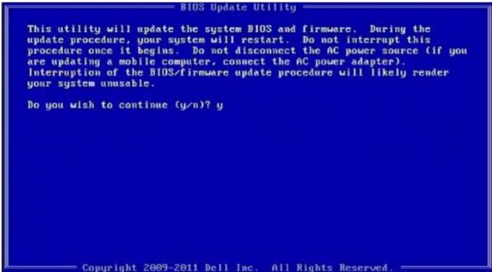
text_image
BIOS Update Utility This utility will update the system BIOS and firmware. During the update procedure, your system will restart. Do not interrupt this procedure once it begins. Do not disconnect the AC power source (if you are updating a mobile computer, connect the AC power adapter). Interruption of the BIOS/firmware update procedure will likely render your system unusable. Do you wish to continue (y/n)? y Copyright 2009-2011 Dell Inc. All Rights Reserved.Figure 4. DOS BIOS Update Screen
System and setup password
You can create a system password and a setup password to secure your computer.
Password type Description
System password Password that you must enter to log on to your system.
Setup password Password that you must enter to access and make changes to the BIOS settings of your computer.
CAUTION: The password features provide a basic level of security for the data on your computer.
CAUTION: Anyone can access the data stored on your computer if it is not locked and left unattended.
NOTE: Your computer is shipped with the system and setup password feature is disabled.
Assigning a system password and setup password
You can assign a new System Password only when the status is in Not Set.
To enter the system setup, press F2 immediately after a power-on or re-boot.
1 In the System BIOS or System Setup screen, select Security and press Enter. The Security screen is displayed.
2 Select System Password and create a password in the Enter the new password field. Use the following guidelines to assign the system password:
• A password can have up to 32 characters.
• The password can contain the numbers 0 through 9.
- Only lower case letters are valid, upper case letters are not allowed.
- Only the following special characters are allowed: space, ("), (+), (.), (-), (.), (/), (:), ([], (), (]), (^).
3 Type the system password that you entered earlier in the Confirm new password field and click OK.
4 Press Esc and a message prompts you to save the changes.
5 Press Y to save the changes.
The computer reboots.
Deleting or changing an existing system and/or setup password
Ensure that the Password Status is Unlocked (in the System Setup) before attempting to delete or change the existing System and/or Setup password. You cannot delete or change an existing System or Setup password, if the Password Status is Locked. To enter the System Setup, press F2 immediately after a power-on or reboot.
1 In the System BIOS or System Setup screen, select System Security and press Enter. The System Security screen is displayed.
2 In the System Security screen, verify that Password Status is Unlocked.
3 Select System Password, alter or delete the existing system password and press Enter or Tab.
4 Select Setup Password, alter or delete the existing setup password and press Enter or Tab.
NOTE: If you change the System and/or Setup password, re-enter the new password when promoted. If you delete the System and/or Setup password, confirm the deletion when promoted.
5 Press Esc and a message prompts you to save the changes.
6 Press Y to save the changes and exit from System Setup.
The computer reboots.
Troubleshooting
Dell Enhanced Pre-Boot System Assessment (ePSA) diagnostic 3.0
You can invoke the ePSA diagnostics by either:
- Press the F12 key when the system boots and choosing Diagnostics option.
- Press Fn+PWR when the system boots.
For more details, see Dell EPSA Diagnostic 3.0.
Diagnostic LED
This section details the diagnostic features of the battery LED in a notebook.
Instead of beep codes errors are indicated via the bicolor Battery Charge LED. A specific blink pattern is followed by flashing a pattern of flashes in amber, followed by white. The pattern then repeats.

NOTE: The diagnostic pattern will consist of a two digit number being represented by a first group of LED blinks (1 through 9) in amber, followed by a 1.5 second pause with the LED off, and then a second group of LED blinks (1 through 9) in white. This is then followed by a three second pause, with the LED off, before repeating over again. Each LED blink takes 0.5 seconds.
The system will not shutdown when displaying the Diagnostic Error Codes. Diagnostic Error Codes will always supersede any other use of the LED. For instance, on Notebooks, battery codes for Low Battery or Battery Failure situations will not be displayed when Diagnostic Error Codes are being displayed:
Table 12. LED pattern
Blinking pattern Problem Description Suggested Resolution
Amber White
| 2 1 processor processor failure |
| 2 2 system board, BIOS ROM system board, covers BIOS corruption or ROM error |
| 2 3 memory no memory/no RAM detected |
| 2 4 memory memory failure/RAM failure |
| 2 5 memory invalid memory installed |
| 2 6 system board; chipset system board/ chipset error |
| 2 7 display | display failure |
| 3 1 RTC power failure | coin-cell battery failure |
| 3 2 PCI/Video | PCI/Video card/chip failure |
| 3 3 BIOS recovery 1 | recovery image nor found |
| 3 4 BIOS recovery 2 | recovery image found but invalid |
Real Time Clock (RTC) reset
The Real Time Clock (RTC) reset function allows you or the service technician to recover the recently launched model Dell Latitude and Precision systems from select No POST/No Boot/No Power situations. You can initiate the RTC reset on the system from a power off state only if it is connected to AC power. Press and hold the power button for 25 seconds. The system RTC reset occurs after you release the power button.

NOTE: If AC power is disconnected from the system during the process or the power button is held longer than 40 seconds, the RTC reset process is aborted.
The RTC reset will reset the BIOS to Defaults, un-provision Intel vPro and reset the system date and time. The following items are unaffected by the RTC reset:
- Service Tag
- Asset Tag
- Ownership Tag
- Admin Password
- System Password
- HDD Password
• Key Databases - System Logs
The following items may or may not reset based on your custom BIOS setting selections:
- The Boot List
- Enable Legacy OROMs
- Secure Boot Enable
- Allow BIOS Downgrade