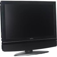
PL17 - Screen Proview - Free user manual and instructions
Find the device manual for free PL17 Proview in PDF.


User questions about PL17 Proview
0 question about this device. Answer the ones you know or ask your own.
Ask a new question about this device
Download the instructions for your Screen in PDF format for free! Find your manual PL17 - Proview and take your electronic device back in hand. On this page are published all the documents necessary for the use of your device. PL17 by Proview.
USER MANUAL PL17 Proview
natural_image
Computer monitor displaying a field of sunflowers in bloom, no visible text or symbols on the image itself.©2006 by Proview®. All rights reserved.
Copyright protection claimed includes all forms and matters of copyrightable material and information now allowed by statutory judicial law or hereinafter granted, including without limitation, material generated from the software programs which are displayed on the screen such as icons, screen displays, looks, etc.
All Proview® product names mentioned in this publication are trademarks of Proview. Other company trademarks are also acknowledged.
Changes are periodically made to this document. Changes, technical inaccuracies, and typographic errors will be corrected in subsequent editions.
Table of Contents
CE Marking Declaration Of Conformity 4
Federal Communications Commission (FCC) Statement ....5
Important Safety Instructions....6
Chapter 1 Introduction
Features....9
Package Contents ....10
Front View and Controls 11
Chapter 2 Installation
Connecting Your LCD Monitor to a Computer 12
Installing Your LCD Monitor ....13
Chapter 3 OSD Menu
Using the OSD Menu ....15
The OSD Options ......16
Chapter 4 Technical Information
Preset Mode Timing Chart ....19
D-SUB Connector PIN Assignment 20
Plug and Play 21
Visual Inspection 21
Troubleshooting 22
Specifications 23
Recycling Place
EUROPE
When disposing of Proview Monitors in Europe, please contact one of the following three locations to make arrangements for recycling.
■Proview International (UK) Limited
30 The Avenue, Watford, Hertfordshire
WD17 4AE United Kingdom
Timothy Lo
Tel: +44-1923-248-111
Fax: +44-923-248-222
Email: tim.lo@proview.co.uk
■PGL Europe B.V. (Proview Group Limited Rotterdam)
Satijnbloem 37,
3068 JP
Rotterdam
Hollande
David Hsieh
Tel: +31-10-238-1090
Fax: +31-10-238-1091
Email: david@proview-group.nl
Koal bvba
Email: rma@proview-repair.com
leo.starckx@proview-repair.com
ASIA
When disposing of Proview Monitors in Asia, please contact the following location to make arrangements for recycling.
■Proview Technology (ShenZhen) Co., Ltd.
North Block 21, 23# Shatoukok Free Trade Zone, ShenZhen, China.
Mr. Dennis Chang
Tel: +86-755-2526-1512
Fax: +86-755-2526-1565
Email:recycling@proview.com.cn
AMERICA
When disposing of Proview Monitors in America, please call the following location to make arrangements for recycling.
■Proview Technology, Inc. (U.S.A.)
7373 Hunt Avenue, Garden Grove, CA 92841 U.S.A.
Patrick Yen
Tel:+714-799-3865
Fax:+714-379-6290
Email:pyen@proview.net
"THIS DISPLAY UNIT IS AN ELECTRIC DEVICE WHICH MAY CONTAIN HAZARDOUS MATERIALS AND COMPONENTS, AND WHICH MUST BE DISPOSED OF AT END OF LIFE ACCORDING TO THE PROPER PROCEDURE"
CE Marking Declaration Of Conformity
This LCD monitor complies with the requirements of the EC Directive 89/336/EEC “EMC Directive” and 73/23/EEC “Low Voltage Directive” as amended by Directive 93/68/EEC.
The electro-magnetic susceptibility has been chosen at a level that gives correct operation in residential areas, business and light industrial premises and small-scale enterprises, inside as well as outside of the buildings.
All places of operation are characterized by their connection to the public low voltage power supply system.
Federal Communications Commission (FCC) Statement
This equipment has been tested and found to comply with the limits of a class B digital device, pursuant to Part 15 of the FCC Rules. These limits are designed to provide reasonable protection against harmful interference in a residential installation. This equipment generates, uses and can radiate radio frequency energy and, if not installed and used in accordance with the instructions, may cause harmful interference to radio communications. However, there is no guarantee that interference will not occur in a particular installation. If this equipment does cause harmful interference to radio or television reception, which can be determined by turning the equipment off and on, the user is encouraged to try to correct the interference by one or more of the following measures:
- Reorient/Relocate the receiving antenna.
- Increase the separation between the equipment and receiver.
- Connect the equipment into an outlet on a circuit which is different from what the receiver is connected to.
- Consult the dealer or an experienced radio/TV technician for help.

CAUTION:
Changes or modifications not expressly approved by the manufacturer responsible for compliance could void the user authority to operate the equipment.
Important Safety Instructions
To prevent any injuries, the following safety precautions should be observed in the installation, use, servicing and maintenance of this equipment.
Before operating this equipment, please read this manual completely, and keep it nearby for future reference.
Warnings

- Do not place the equipment on any uneven or unstable carts, stands, tables, shelves etc. The equipment may fall, causing serious injury to children or adults and serious damage to the equipment itself.
- Use only a cart or stand recommended by the manufacturer. This equipment and recommended cart or stand should be handled with care. Quick stops, excessive force, and uneven surfaces may cause the equipment and cart/stand to overturn.
- Do not disable the 3-wire grounding type plug. The grounding pin on the 3-prong plug is an important feature. Removing the grounding pin will increase the risk of damaging the equipment. If you can not fit the plug into the electrical outlet, contact an electrician to install a grounding outlet.
- Always operate this equipment from the type of power source indicated on the rear of the serial/model plate.
- Never overload wall outlets and extensions.
- Use and handle the power cord with care.
- Do not place any heavy objects on the AC power cord.
- Do not pull the AC power cord. Do not handle the AC power cord with a wet hand.
- Do not touch the power cord and antenna cable during lightning.
- Remove the plug from the wall outlet if the equipment will not be used for a long period of time.
- Do not place, use or handle this equipment near water.
- Never expose the equipment to liquid, rain, or moisture. Seek qualified service if any of the above is spilled into the equipment.
- Do not attempt to service the equipment yourself.
- Opening and removing the covers may expose you to dangerous voltage or other hazards and may void your warranty. Refer service to qualified personnel.
- Always remove the power cord from the outlet before cleaning the equipment.
- Never use liquid or aerosol cleaners on the equipment. Clean only with a soft dry cloth.
- Do not expose the equipment to extreme temperature or to direct sunlight, as the equipment may heat up and suffer damage.
- Do not install the equipment near any heat sources such as radiators, heat registers, stoves, or any other apparatus that might produce heat.
- Do not block any ventilating openings. Leave an open space around the equipment.
- Never place the equipment : on a bed, sofa, rug, or any other similar surfaces; too close to drapes/curtains/walls, in a bookcase, built-in cabinet, or any other similar places that may cause poor ventilation.
- If any of the following conditions occur, unplug the power cord from the outlet and request service from qualified personnel.
a. The power cord or plug is damaged.
b. Liquid is spilled into the product.
c. An object falls onto or into the product.
d. The product has been dropped or damaged.
e. The product's display is abnormal.
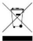
DISPOSAL OF WASTE ELECTRONIC EQUIPMENT BY PRIVATE HOUSEHOLDS WITHIN THE EUROPEAN UNION
This sign indicates that this product may not be disposed of with your regular household waste. The recycling and separate collection of such products is your responsibility. Please drop off the above-mentioned waste at a designated place for recycling waste electrical and electronic equipment. If you do not know where to drop off your waste equipment for recycling, please contact your local city office or household waste collection service.
INTRODUCTION
Features

- FAST VIDEO RESPONSE
Fast action media such as gaming, DVD and video conferencing will playback smoothly thanks to the fast video response time of the LCD panel.

• HIGH CONTRAST RATIO
Colors will appear vibrant and lifelike producing superior image quality.

• ANTI-REFLECTIVE COATING
Special panel coating to efficiently reduce distracting glare on images viewed.
- PLUG-AND-PLAY CAPABILITY
Easy trouble-free configuration and set-up.

• BUILT-IN POWER TO SAVE SPACE
All components of the power adapter are designed into the chassis. There will not be adapter occupying the desktop space.
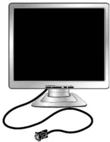
Package Contents
Make sure all of the following contents are included in the box.
If any items are missing, please return this product to the original place of purchase.
natural_image
Illustration of a computer monitor with a cable and connector, no text or symbols presentLCD Monitor : V513/V713/V913
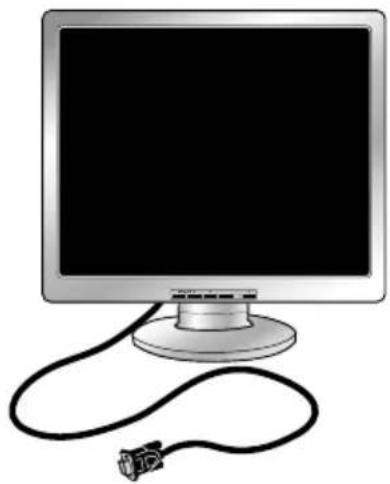
natural_image
Illustration of a computer monitor with a cable and connector, no text or symbols presentLCD Monitor : SP516/SP716/SP916
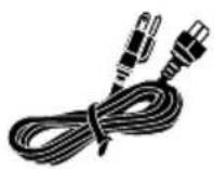
Power Cord*
Quick Guide
Warranty Card

CD-ROM
(Driver/Manual)
* Power cord specification : H05 VV-F 3G 0.75mm²

CAUTION:
Be sure to save original box and all packing material for future transport of monitor.
Front View and Controls
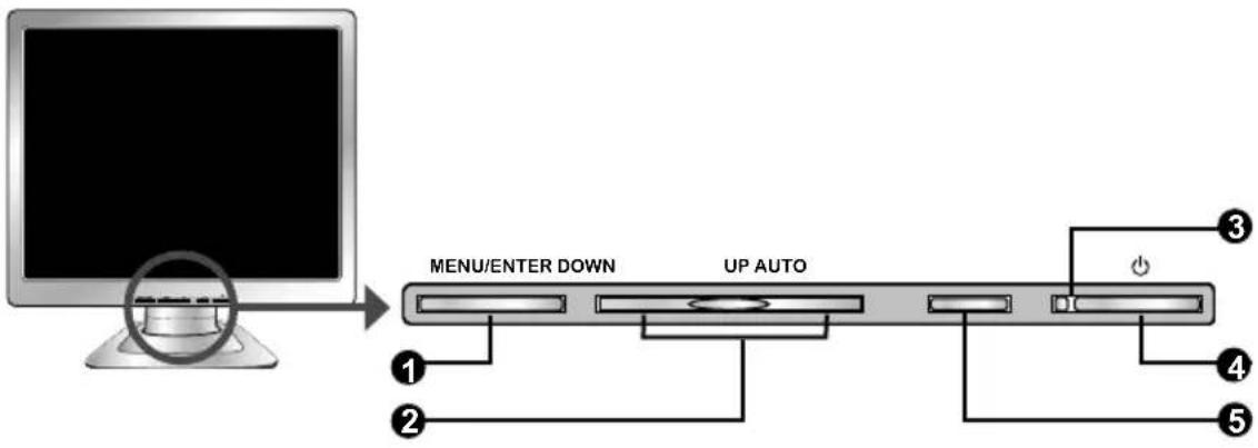
V513/V713/V913
flowchart
graph LR
    A["Computer monitor"] --> B["MENU/ENTER DOWN"]
    B --> C["UP AUTO"]
    C --> D["Port 3"]
    C --> E["Port 4"]
    C --> F["Port 5"]
    C --> G["Port 2"]
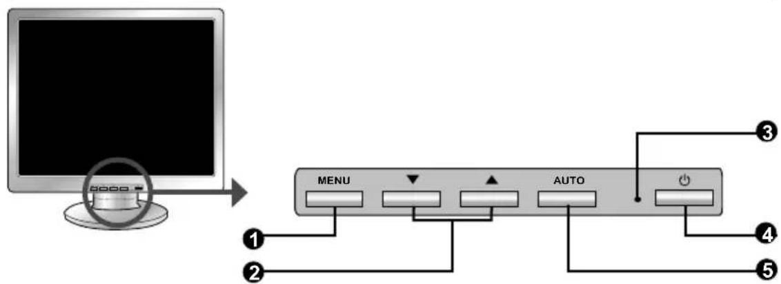
SP516/SP716/SP916
flowchart
graph LR
    A["Computer monitor with 8000 button"] --> B["MENU"]
    B --> C["↓"]
    B --> D["▲"]
    B --> E["AUTO"]
    E --> F["Power Button"]
    style A fill:#f9f,stroke:#333
    style B fill:#ccf,stroke:#333
    style C fill:#cfc,stroke:#333
    style D fill:#fcc,stroke:#333
    style E fill:#cff,stroke:#333
    style F fill:#ffc,stroke:#333
ITEM DESCRIPTION
1 MENU Press once to display the OSD (On Screen Display). And ENTER press to activate the items you highlight.
2 ▲▼ In OSD mode, press the ▲▼/DOWN/UP buttons to move DOWN/UP the selection highlight to the next menu item counterclockwise or clockwise, respectively.
3 LED The LED light indicates when the LCD monitor is activated (green light indicates power on and amber light indicates power saving).
4 🎨urns the LCD monitor on and off.
5 AUTO Press to automatically adjust the display settings to optimize performance based on the D-SUB signal.
INSTALLATION
Refer to the owner's manual of the computer for connections.
In the process of connecting external equipment, do not connect any AC power cords to wall outlets until all other connections are completed.
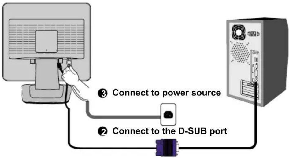
Connecting Your LCD Monitor to a Computer
1 Turn off the computer and unplug the power cord.
2 Connect the signal cable to the VGA port on the back of the computer.
3 Connect the power cord to wall outlet and LCD monitor.
4 Press the ⏻ button, located on the bottom side of the main unit to turn the monitor on, then turn the computer on. If the monitor displays an image, the monitor is successfully installed. If no image is displayed, check all connections.
text_image
③ Connect to power source ② Connect to the D-SUB port
NOTE:
Unplug the monitor before installation to avoid electric shock or damage.

NOTE:
The ⏻ button is used for switching the LCD monitor on and off, it does not disconnect the device from the main voltage. To completely disconnect the main voltage, please remove the power plug from the socket.

NOTE:
The LED indicator is green when the monitor operates normally and will turn to amber when in power saving mode. When the monitor is off, the LED turns dark.
Installing Your LCD Monitor
Follow the instructions below to set up and install the monitor.
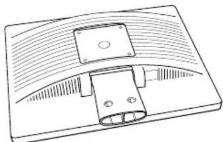
1 The package contains:
Display unit
Stand
natural_image
Technical line drawing of a mechanical component with curved surfaces and mounting holes (no text or symbols)DISPLAY UNIT
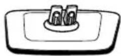
STAND
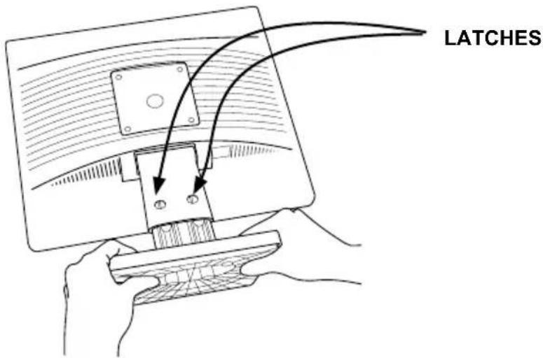
2 Cover an even stable surface with a soft cloth. Place the unit face-down on the cloth. Fit the stand onto the bottom of the display unit as shown, then push until the two latches snap into their sockets.
text_image
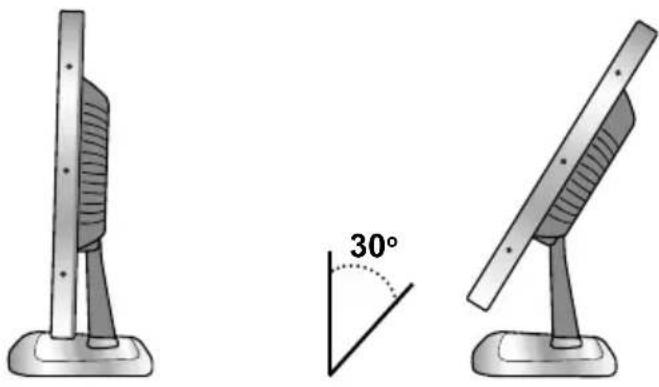
LATCHESIn order to ensure a healthy and relaxed body position when using the monitor at visual display workstations, you are able to adjust the monitor's angle of the stand.
The angle of the LCD monitor may be adjusted approximately 30 degrees.
natural_image
Two identical stand-mounted devices with a 30-degree angle marked between them, no text or symbols present.OSD Menu
Using the OSD Menu
To create the best picture, your LCD monitor has been preset at the factory with the Preset Mode Timing shown on page 19.
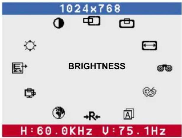
The OSD (On Screen Display) Menu allows the user to adjust various settings and options by following the steps below.
1 Press the MENU button to display the OSD. The OSD main menu provides an overview of the selection of controls available.
text_image
1024x768 BRIGHTNESS H:60.0KHz U:75.1Hz2 Press the ▲▼ or DOWN/UP button to highlight the desired icon. Then, press the MENU button to activate the highlighted icon
3 Press the ▲▼ or DOWN/UP button to change the value of the selected item.
4 Select the EXIT icon to exit the OSD.
5 Repeat steps 1 through 4 to make further adjustments. All changes are stored immediately.
The OSD Options
The OSD menu includes the following options:
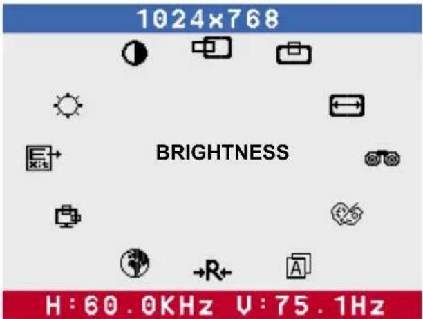
text_image
1024x768 BRIGHTNESS H:60.0KHz U:75.1HzBRIGHTNESS
Controls the overall brightness.
CONTRAST
Controls the difference between the brightest and darkest regions of the picture.
H. POSITION
Adjusts the position of the picture left and right in the window.
V POSITION
Adjusts the position of the picture up and down in the window.
HSIZE
Adjusts the width of the picture.
PHASE
Adjusts signal phase, which can improve focus clarity and image stability.

Allows selection of the general color tint:
Select User Mode, WARM, or COOL.
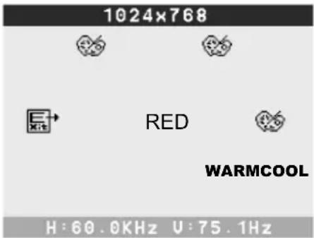
text_image
1024x768 RED WARMCOOL H:60.0KHz U:75.1HzSelect User Mode
Allows the user to adjust red, green and blue color component levels independently.
COOL
Inclines colors toward the blue end of the spectrum. Fixes the red, green and blue component levels at factory settings; they cannot be independently adjusted.
WARM
Inclines colors toward the red end of the spectrum. Fixes the red, green and blue component levels at factory settings; they cannot be independently adjusted.

Exits the OSD menu.

Selects to automatically adjust the display settings to optimize performance based on the D-SUB signal.

Restores all options to the factory settings.

Controls which language is used on all the on-screen menus.

Changes the position of the OSD.

POSITION
Moves the OSD left and right in the window.

POSITION
Moves the OSD up and down in the window.

KIT
Exits the OSD menu.

Exits the OSD.
Technical Information
Preset Mode Timing Chart
The screen image has been optimized during manufacture for the display modes listed below.
Video signal: (IBM PC/AT)
| Dot X Line | Horizontal Frequency(kHz) | Vertical Frequency(Hz) |
| 720 x 400 31.47 | 70.00 | |
| 640 x 480 31.47 | 60.00 | |
| 37.86 72.80 | ||
| 37.50 75.00 | ||
| 800 x 600 35.16 | 56.25 | |
| 37.88 60.30 | ||
| 48.08 72.20 | ||
| 46.87 75.00 | ||
| 1024 x 768 48.36 | 60.00 | |
| 56.48 70.10 | ||
| 60.02 75.00 | ||
| 1280 x 1024 63.98 | 60 | |
| 79.98 75 |
D-SUB Connector PIN Assignment
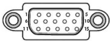
text_image
1 6 11 5 10 15| PIN | DESCRIPTION |
| 1 Red | |
| 2 Green | |
| 3 Blue | |
| 4 Ground | |
| 5 Self Test | |
| 6 Red Ground | |
| 7 Green Ground | |
| 8 Blue Ground | |
| 9 5 VDC | |
| 10 Ground | |
| 11 Ground | |
| 12 SDA (FOR DDC) | |
| 13 H. Sync | |
| 14 V. Sync | |
| 15 | SCL (FOR DDC) |
Plug and Play
This monitor conforms to the VESA DDC (Display Data Channel) standard, which means that when it is used with a DDC compatible video card, the monitor is easier to set up. With VESA DDC 1/2B, when the monitor is turned on, it will automatically notify a windows 9X/2000/XP host computer of its scanning frequencies, capabilities and characteristics. Windows 9X/2000/XP will automatically recognize the presence of the monitor and select the appropriate display resolution.
Visual Inspection
Permanently unlit or lit pixels
The standard of production techniques today cannot guarantee an absolutely fault free LCD display. A few isolated permanently lit or unlit pixels may be present. The maximum permitted number of pixel faults is stipulated in the stringent international standard ISO 13406-2 (Class II).
Example:
A 17" flat-screen monitor with a resolution of 1280 x 1024 has 1280 x 1024 = 1310720 pixels. Each pixel consists of three subpixels (red, green and blue), so there are about 4 million dots in total.
According to ISO 13406-2 (Class II), a maximum of 6 pixels and 7 subpixels may be defective, i. e. a total of 25 faulted dots.
Troubleshooting
Before consulting service personnel, check the following chart for a possible cause and solution to the trouble you are experiencing.
1 Monitor will not turn on
- Make sure the power cord is plugged in.
2 No picture
- Make sure the power cord is plugged in.
- Check the signal cable connecting the LCD monitor and the computer (refer to page 12).
- Press the button on the front panel of the monitor.
3 Poor picture or abnormal picture
- Press the MENU button to adjust the Brightness Contrast option in the OSD.
- Adjust the Color Select option in the OSD.
- Press the AUTO button on the front panel of the monitor, to automatically adjust the display mode.
4 Out of range message appears
- If using Windows 9X/2000/XP, wait a few seconds; once Windows detects the problem, a dialog will appear allowing you to manually set up the video mode according to the preset mode timing chart (refer to page 19).
Specifications
| MODEL V513 V713 V913 | ||||
| LCD Panel Panel Size 15" TFT LCD 17" TFT LCD 19" TFT LCD | ||||
| Brightness 250 260 280 | ||||
| Contrast Ratio 500:1 500:1 500:1 | ||||
| Dot Pitch 0.297mm x 0.297mm 0.264mm x 0.264mm 0.294mm x 0.294mm | ||||
| Max. Resolution 1024x768 1280x1024 1280x1024 | ||||
| Input Connector D-SUB | D-SUB | D-SUB | ||
| Power Source | AC100-240V, 50-60Hz | AC100-240V, 50-60Hz | AC100-240V, 50-60Hz | |
| Power Consumption | 36W | 48W | 48W | |
| Dimension(WxHxD) | 345x333x166 mm | 378x379x180 mm | 421x414x194 mm | |
| MODEL | SP516 | SP716 | SP916 | |
| LCD Panel Panel Size 15" TFT LCD 17" TFT LCD 19" TFT LCD | ||||
| Brightness 250 260 280 | ||||
| Contrast Ratio 500:1 500:1 500:1 | ||||
| Dot Pitch 0.297mm x 0.297mm 0.264mm x 0.264mm 0.294mm x 0.294mm | ||||
| Max. Resolution 1024x768 1280x1024 1280x1024 | ||||
| Input Connector D-SUB | D-SUB | D-SUB | ||
| Power Source | AC100-240V, 50-60Hz | AC100-240V, 50-60Hz | AC100-240V, 50-60Hz | |
| Power Consumption | 36W | 48W | 48W | |
| Dimension(WxHxD) | 349x335x172 mm | 378x382x192 mm | 427x416x210 mm | |
Changes are periodically made to this specifications.
Current specifications may also be obtained via the internet,
www.proview.com