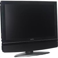
HV147 - TV Proview - Free user manual and instructions
Find the device manual for free HV147 Proview in PDF.


User questions about HV147 Proview
0 question about this device. Answer the ones you know or ask your own.
Ask a new question about this device
Download the instructions for your TV in PDF format for free! Find your manual HV147 - Proview and take your electronic device back in hand. On this page are published all the documents necessary for the use of your device. HV147 by Proview.
USER MANUAL HV147 Proview
natural_image
Computer monitor displaying a scenic view of a castle with red flowers in the foreground (no text or symbols visible)Component Video Inputs
Multiple I/O Support
Digital Noise Reduction
Progressive Scan Display
Excellent Audio Performance with BBE
HV-147
FEDERAL COMMUNICATIONS COMMISSION[F.C.C] STATEMENT
This equipment has been tested and found to comply with the limits of a class B digital device. Pursuant to Part 15 of the FCC Rules. These limits are designed to provide reasonable protection against harmful interference in a residential installation. This equipment generates, uses and can radiate radio frequency energy and, if not installed and used in accordance with the instructions, may cause harmful interference to radio communications. However, there is no guarantee that interference will not occur in a particular installation. If this equipment does cause harmful interference to radio or television reception, which can be determined by turning the equipment off and on, the user is encouraged to try to correct the interference by one or more of the following measures:
- Reorient/Relocate the receiving antenna.
- Increase the separation between the equipment and receiver.
- Connect the equipment into an outlet on a circuit which is different from what the receiver is connected to.
- Consult the dealer or an experienced radio/TV technician for help.
CAUTION
Changes or modifications not expressly approved by the manufacturer responsible for compliance could void the user authority to operate the equipment.
IMPORTANT SAFETY INSTRUCTIONS
WARNING
To reduce the risk of fire or electric shock, do not expose this equipment to rain or moisture.
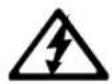
CAUTION
RISK OF ELECTRIC SHOCK DO NOT OPEN

CAUTION: TO REDUCE THE RISK OF ELECTRIC SHOCK,
DO NOT REMOVE COVER (OR BACK).
NO USER-SERVICEABLE PARTS INSIDE.
REFER SERVICING TO QUALIFIED SERVICE PERSONNEL.
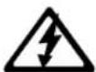
This symbol is intended to alert the user to avoid the risk of electric shock, do not disassemble this equipment by anyone except a qualified service personnel.

This symbol is intended to alert the user to the presence of important operating and maintenance instructions in the literature accompanying the appliance.
CAUTION
Use of controls, adjustments or performance of procedures other than those specified herein may result in hazardous radiation exposure
IMPORTANT SAFETY INSTRUCTIONS
To prevent any injuries, the following safety precautions should be observed in the installation, use, servicing and maintenance of this equipment. Before operating this equipment, please read this manual completely, and keep it nearby for future reference.

natural_image
Symbolic icon of a person climbing a ladder inside a blue circle with a no-smoking symbol (no text or numbers present)- Do not place the equipment on any uneven or unstable carts, stands, tables, shelves etc..
The equipment may fall, causing serious injuries to children or adults and serious damage to the equipment itself.
■ Use only a cart or stand recommended by the manufacturer. This equipment and recommended cart or stand should be handled with care. Quick stops, excessive force, and uneven surfaces may cause the equipment and recommended cart or stand to overturn.

natural_image
Blue circular icon showing a computer monitor connected to a plug with a switch (no text or symbols)■ Do not disable the 3-wire grounding type plug. The grounding pin on the 3-prong plug is an important feature. Removing the grounding pin will increase the risk of damaging the equipment.
If you can not fit the plug into the electrical outlet, contact an electrician to install a grounding outlet.
■ Always operate this equipment from the type of power source indicated on the rear of the serial/model plate.
natural_image
Circular diagram showing electrical connections with a fuse and lightning bolt, no text or symbols present■ Never overload wall outlets and extensions.
■ Use and handle the power cord with care.
■ Do not place any heavy objects on the AC power cord.
■ Do not pull the AC power cord. Do not handle the AC power cord with a wet hand.
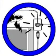
Do not touch the power cord and antenna cable during lightning.
- When the equipment has not been used for a long period of time, unplug it from the wall outlet.

text_image
Blue circular sign with a crossed-out cloud and raindrops, indicating no pollution or fire resistance.■ Do not place, use or handle this equipment near water.
■ Never expose the equipment to liquid, rain, or moisture. Seek for service if any of the above is spilled into the equipment.

text_image
Prohibition sign with sun and leaves symbol crossed out, indicating no prohibition or anti-protection■ Do not expose the equipment to extreme temperature or to direct sunlight, the equipment may heat up and cause damage to the equipment.
■ Do not install the equipment near any heat sources such as radiators, heat registers, stoves, or any other apparatus that might produce heat.
IMPORTANT SAFETY INSTRUCTIONS
text_image
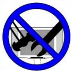
Prohibition sign with crossed-out tools and a crossed-out device, indicating no intervention or anti-protection.■ Do not attempt to service the equipment yourself.
■ Opening and removing the covers may expose you to dangerous voltage or any other hazards and may terminate your warranty. Refer service from qualified personnel.
text_image
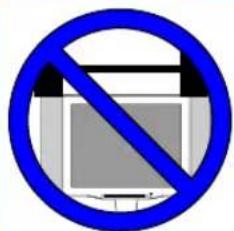
Blue prohibition sign with a crossed-out document icon, indicating no restrictions or exclusion■ Do not place or drop any other objects on top.
■ Do not insert anything into the ventilation holes of your equipment. Inserting any metal or flammable objects may result to fire or electric shock
text_image
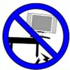
Prohibition sign with crossed-out monitor and arrow, indicating no liability or prohibition■ Do not place the equipment on uneven or unstable carts, stands, tables, shelves etc...
The equipment may fall, causing serious injuries to children or adults and serious damage to the equipment itself.
■ Always place the equipment on the floor or on a surface that is sturdy, level, stable and strong enough to support the weight of the equipment.
text_image
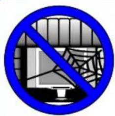
Blue circular sign with a prohibition symbol over a computer monitor and spiderweb, indicating no restrictions on the computer screen.■ Do not block any ventilating openings, leave an open space around the equipment.
■ Never place the equipment:
• on a bed, sofa, rug, or any other similar surfaces;
• too close to drapes/curtains/walls, in a bookcase, built-in cabinet, or any other similar places that may cause poor ventilation.

natural_image
Illustration of a hand using a tool to smoke or smoke from a computer monitor, enclosed in a blue circular border (no text or symbols)■ Always remove the cord from the outlet before cleaning the equipment.
■ Never use liquid or aerosol cleaners on the equipment. Clean only with a soft dry cloth.
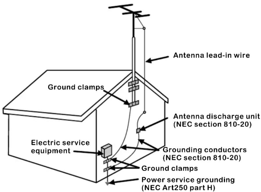
EXAMPLE OF OUTDOOR ANTENNA GROUNDING
If an outdoor antenna is connected, follow the precautions below:
An outdoor antenna should not be located anywhere that can be in contact of overhead power lines, or any other electric light or power circuits.
When installing an outdoor antenna system, extreme caution should be taken to prevent contact with power lines. Direct contact with power lines may be fatal and should be avoided at all costs.
Section 810 of National Electrical Code (NEC) provides information with respect to proper grounding of the mast and supporting structure, grounding of the lead-in wire to an antenna discharge unit, size of grounding conductors, location of antenna discharge unit, connection to grounding electrodes, and requirements for the grounding electrode.
text_image
Antenna lead-in wire Ground clamps Antenna discharge unit (NEC section 810-20) Electric service equipment Grounding conductors (NEC section 810-20) Ground clamps Power service grounding (NEC Art250 part H)NEC : National Electrical Code
Cable TV (CATV) Connection
NOTE TO CATV SYSTEM INSTALLER
This reminder is provided to call the CATV system installer's attention to Article 820-40 of the National Electrical Code (NEC) that provides guidelines for proper grounding and, in particular, specifies that the cable ground shall be connected to the grounding system of the building accurately, or as close to the point of cable entry as possible.
Use of this TV for other than private viewing of programs broadcasted on UHF, VHF or transmitted by cable companies for the use of the general public may require authorization from the broadcast/cable company, and/or program owner.
A 75-ohm coaxial cable connector is built into the set for easy hookup. When connecting the 75-ohm coaxial cable to the set, place the 75-ohm cable into the ANT. terminal.
Some cable TV companies offer premium pay channels. Since the signals of these premium pay channels are scrambled, a cable TV converter/descrambler is generally provided to the subscriber by the cable TV company.
This converter/descrambler is necessary for normal viewing scrambled channels. (Set your TV to channel 3 or 4, typically one of these channels are used. If this is unknown, consult your cable TV company.)
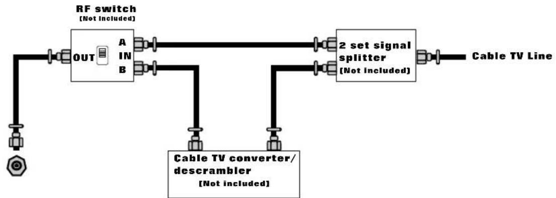
For more specific instructions on installing cable TV, consult your cable TV company, One possible method of utilizing the coverter/descrambler provided by your cable TV company is explained below.
flowchart
graph LR
    A["RF switch\n(Not Included)"] --> B["OUT"]
    B --> C["A IN B"]
    C --> D["2 set signal splitter\n(Not included)"]
    D --> E["Cable TV Line"]
    F["Cable TV converter/descrambler\n(Not included)"] --> D
Please note: the RF switch is required to provide two inputs (A and B). (not included) A position on the RF switch (not included); you can view all unscrambled channels by using the TV channel keys.
B position on the RF switch (not included); you can view all scrambled channels via the converter/descrambler by using the converter channel keys.
ANTENNAS
The antenna requirements for good color TV reception are more important than those of a black & white TV reception. For this reason, a good quality outdoor antenna is strongly recommended.
The following is a brief explanation of the type of connection that is provided with the various antenna systems.
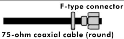
A 75-ohm system is generally a round cable with F-type connector that can easily be attached to a terminal without tools (not included).
text_image
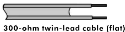
F-type connector 75-ohm coaxial cable (round)A 300-ohm system is a flat twin-lead cable that can be attached to a 75-ohm terminal through a 300-75-ohm adapter (not included).
text_image
300-ohm twin-lead cable (flat)OUTDOOR ANTENNA
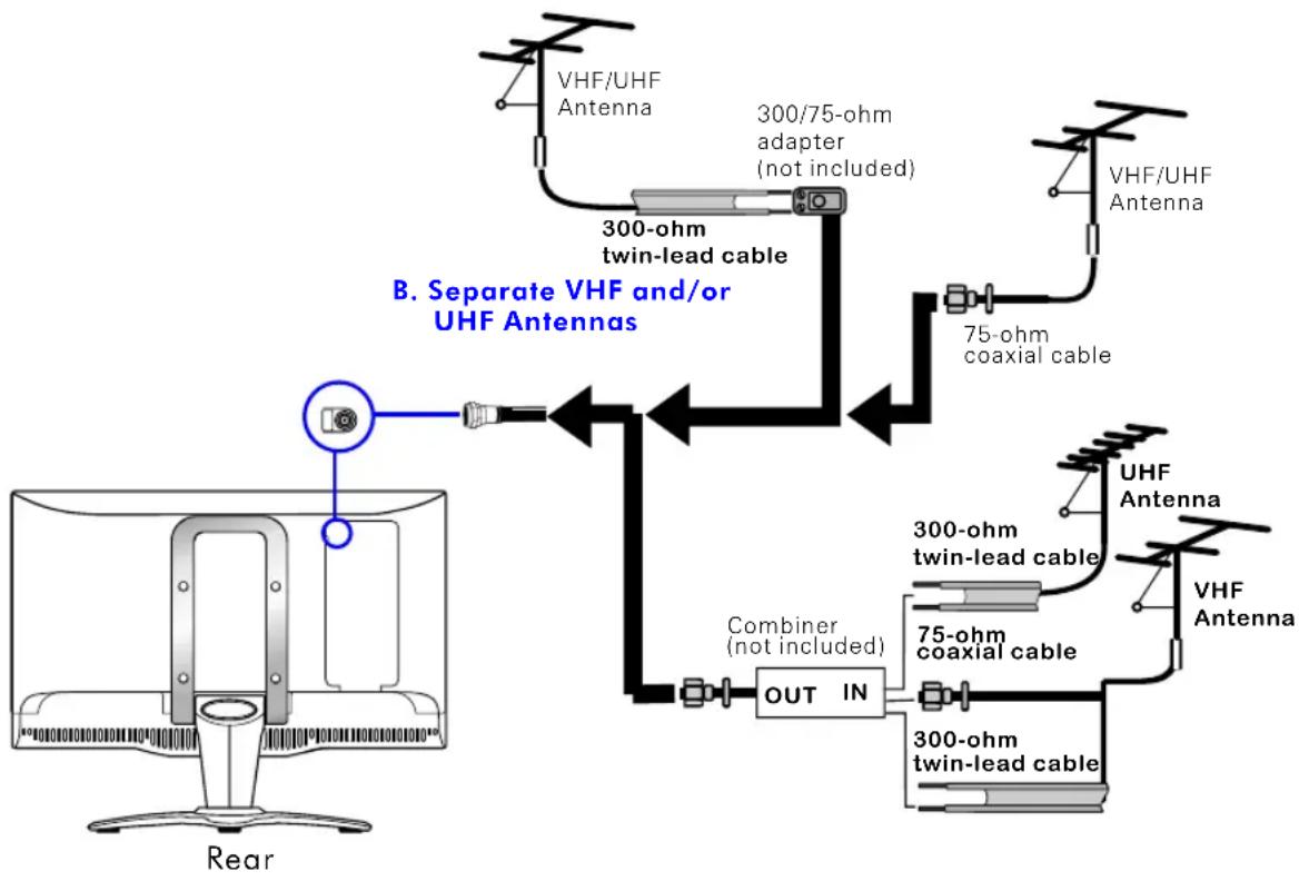
■ Use one of the following two diagrams when connecting an outdoor antenna.
A: Use a VHF/UHF combination outdoor antenna. B: Use a separate VHF and/or UHF outdoor antenna.
Connect the outdoor antenna cable lead-in to the antenna terminal located on the rear of the equipment. A Combination VHF/IIHF antenna
flowchart
graph TD
    A["Rear"] --> B["300-ohm twin-lead cable"]
    B --> C["300/75-ohm adapter (not included)"]
    C --> D["VHF/UHF Antenna"]
    C --> E["75-ohm coaxial cable"]
    E --> F["UHF Antenna"]
    E --> G["300-ohm twin-lead cable"]
    G --> H["75-ohm coaxial cable"]
    H --> I["300-ohm twin-lead cable"]
    I --> J["OUT IN"]
    J --> K["Combiner (not included)"]
    K --> L["B. Separate VHF and/or UHF Antennas"]
CONTENT
PREPARATION
9
Features....9
Package Contents 10
Your LCD TV 11
Front View 11
Rea View 1 12
Rear View 2 13
Remote Control 14
Using your LCD TV....16
INSTALLATION
17
Connecting a TV Cable or an Antenna 17
Connecting a VCR....18
Connecting a DVD Player 19
Connecting a TV Box and Satellite Receiver....20
Connecting a Video Camera 21
Connecting a Subwoofer 22
USING THE FEATURES
23
Setting up the Channel List....23
Watching your LCD TV....24
Using the OSD 25
Viewing the OSD Chart 26
VIDEO ADJUSTMENT 27
PC DISPLAY 28
TV SETTING 29
C.C/V-CHIP 30
AUDIO SETUP 32
SETUP MENU 33
TROUBLESHOOTING
35
SPECIFICATIONS
36
PREPARATION
Congratulations on the purchase of your LCD TV.
Features
Various Audio/Video terminals for external equipment connection

1 Composite A/V terminal
1 S-VIDEO terminal
1 set of COMPONENT Video input terminals
1 VGA connector
2 sets of Audio input terminals
1 Line output (Ear phone)

Component Video Inputs
Offer the best video quality for DVD (480i) connection.

Excellent Audio performance with BBE
BBE High Definition Sound restores clarity and presence for better speech intelligibility and musical realism.

Manufactured under license from BBE Sound, Inc. Licensed by BBE Sound, Inc. Under USP4638258, 5510752 and 5736897. BBE and BBE symbol are registered trademarks of BBE Sound, Inc.
Package Contents
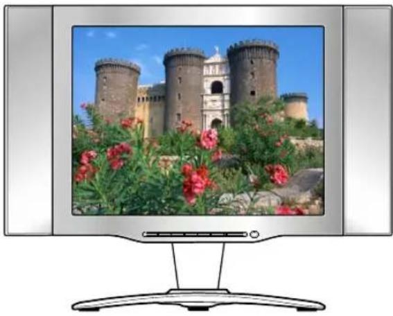
Once you open the box, make sure all of the following contents are included. If you are missing any items, please return this product to the original place of purchase.
natural_image
Computer monitor displaying a historic castle with red flowers in the foreground (no text or symbols visible)LCD TV
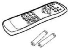
Remote control/AAA batteries
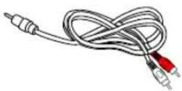
Audio Cable
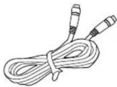
natural_image
Line drawing of a coiled cable with two connectors (no text or symbols)S-Video Cable
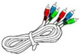
natural_image
Coiled cable with multiple colored connectors (red, green, blue) tied at ends, no text or symbols visible.A/V Cable
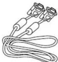
D-SUB Cable
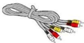
COMPONENT Cable
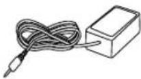
DC Adapter
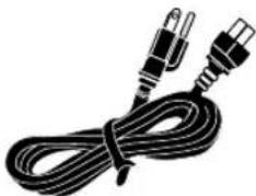
natural_image
Black and white illustration of a coiled electrical plug with two connectors (no text or symbols)Power Cord

User Guide
These items are all you need to set up and operate the LCD TV in its basic configuration.*
* Most components (VCRs, DVD player, etc.) come with the necessary cable for connection. If you want to set up a complex system, you may need to buy extra cable, connector, etc.
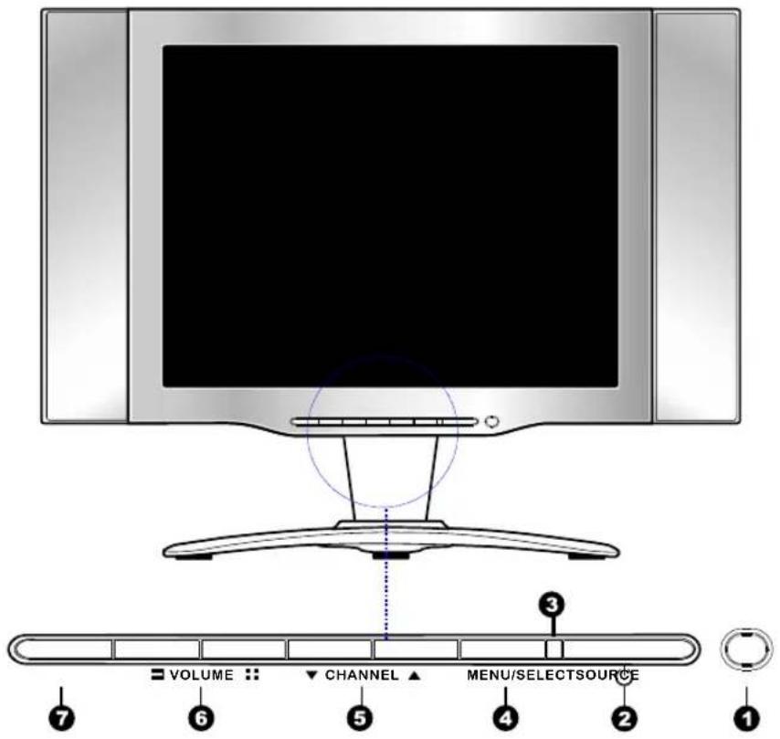
text_image
VOLUME CHANNEL MENU/SELECTSOURCE 1 2 3 4 5 6 7| ITEM | DESCRIPTION | |
| 1 | IR | Infrared Receiver (IR) |
| 2 | POWER ⏻ | Turns the LCD TV on and off . |
| 3 | LED | The LED light indicates when the LCD TV is activated (green light indicates on and amber indicates off). |
| 4 | MENU/SELECT | Press to display the OSD (on screen display), press again to turn the OSD off. |
| 5 | CHANNEL | Scans up and down channels.Selects menu items when in the OSD. |
| 6 | VOLUME | Adjusts the volume up and down.Changes values for menu items when in the OSD. |
| 7 | SOURCE | Selects from different input signal sources. |
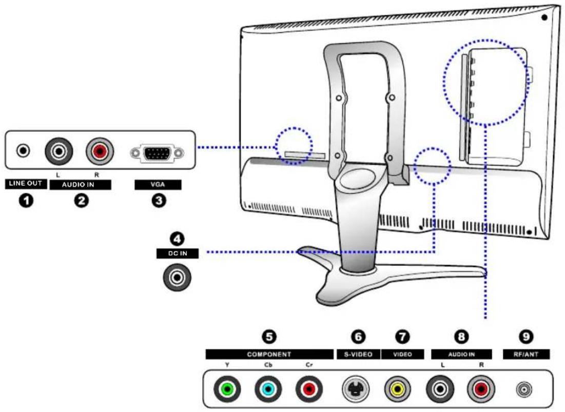
text_image
LINE OUT L R AUDIO IN VGA ① ② ③ ④ DC IN 5 6 7 8 9 COMPONENT S-VIDEO VIDEO AUDIO IN RF/ANT Y Cb Cr L R| ITEM | DESCRIPTION | |
| 1 | LINE IN | Connects the ear phone output jack of the AV equipment. |
| 2 | AUDIO IN | Connects the audio input jack of the satellite receiver or other AV equipment with D-Sub connector. |
| 3 | VGA | Connects the satellite receiver or other AV equipment with D-Sub connector. |
| 4 | DC IN | Connects the DC adapter cord. |
| 5 | COMPONENT | Connects to the component (Y, Cb, Cr) video jacks and your DVD player,or video equipment. |
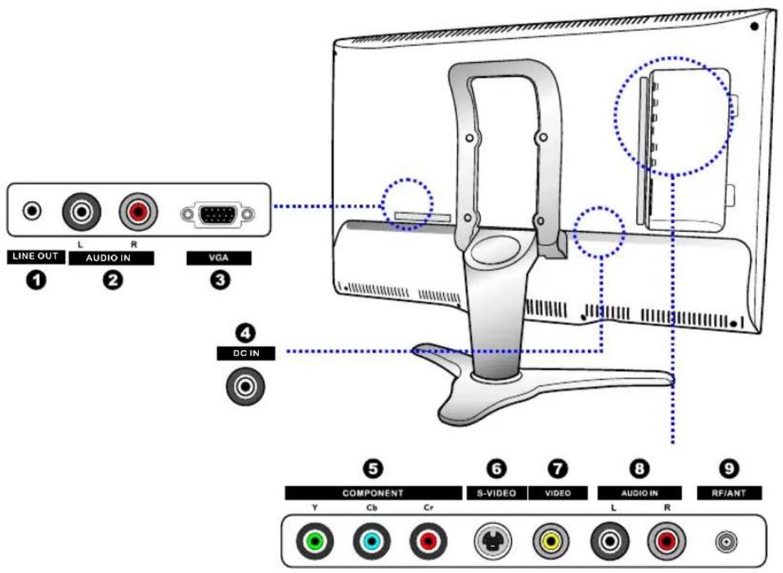
text_image
LINE OUT L R AUDIO IN VGA ① ② ③ ④ DC IN 5 6 7 8 9 COMPONENT S-VIDEO VIDEO AUDIO IN RF/ANT Y Cb Cr L R| ITEM | DESCRIPTION | |
| 6 | S-VIDEO | Connects to the S-VIDEO output jacks and Audio output jacks on your video equipment. |
| 7 | VIDEO | Connects to the composite A/V output jacks on your video equipment. |
| 8 | AUDIO IN | Connects to the audio or video equipment with left and right audio output jacks of the Video or S-Vide or Component (Y, Cb, Cr) |
| 9 | RF/ANT. | The RF input that connects to your VHF/UHF antenna or cable. |
Remote Control
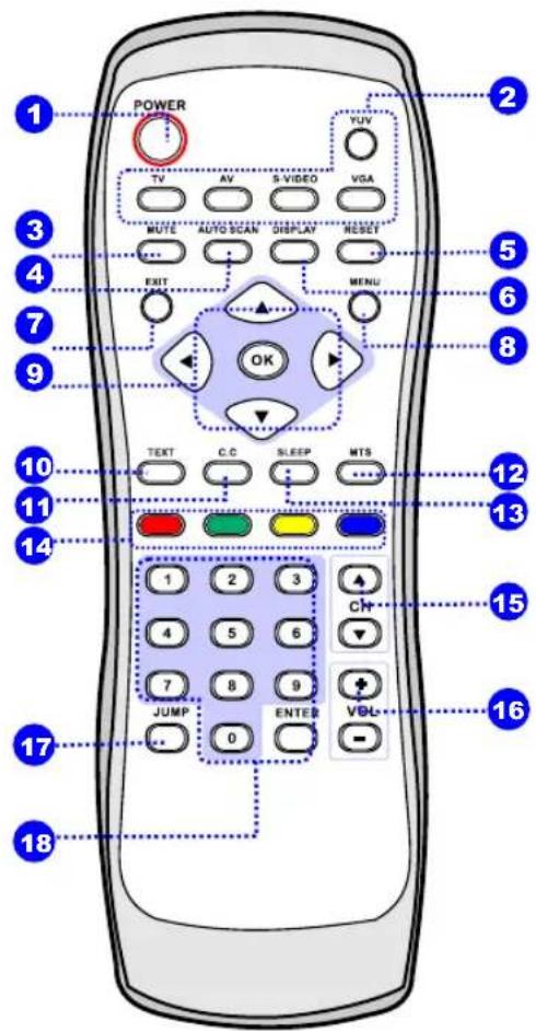
1 POWER
Turns your LCD TV on and off.
2 TV/AV/S-VIDEO/VGA/YUV
Selects the video equipment connected to the video input of your LCD TV: TV/AV/S-VIDEO/VGA/YCbCr
3 MUTE
Mutes and restores your LCD TV sound.
4 AUTO SCAN
Automatically detect and store all active channels in your area.
5 RESET
Restores the factory settings.
6 DISPLAY
Displays information on the LCD TV screen such as channel and channel label.
7 EXIT
Exits the OSD menu.
8 MENU
Displays the OSD menu (on screen display).
Allows you to move, select and set up the OSD options.
10 TEXT
For Europe TV system only. Turns the TELETEXT on and off.
11 cc
CC Turns the Closed Caption on and off.
12 MTS
Selects through the Multi-channel TV Sound(MTS) options: Stereo, SAP, and Mono.
13 SLEEP
Sets up the LCD TV sleep time.
text_image
POWER TV AV S-VIDEO VGA MUTE AUTO SCAN DISPLAY RESET EXIT MENU OK TEXT C.C SLEEP MTS 1 2 3 4 5 6 7 8 9 JUMP ENTER VDL 1814
For Europe TV system only.
To access the item or pages in TELETEXT mode.
15 CH + /-
Scans up and down through channels.
16 VOLUME +/-
Adjusts the volume.
17 JUMP
Switches back and forth between two channels.
18 0\~9,ENTER
Selects and switch to a channel using 0-9 and ENTER.
Remote Control
Installing the batteries in your remote control
1 Slide the back cover to open the battery compartment of the remote control.
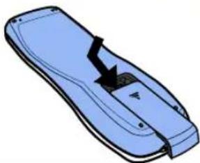
natural_image
Illustration of a blue remote control device with a black arrow pointing to the interior (no text or symbols)2 Insert two AAA size batteries. Make sure to match the (+) and (-) ends of the batteries with the (+) and (-) ends indicated in the battery compartment.
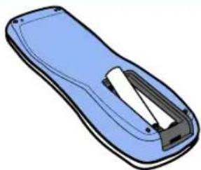
natural_image
Illustration of a blue remote control device with a black handle and silver casing (no text or symbols)3 Slide the cover back into place.
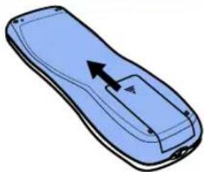
natural_image
Illustration of a blue remote control device with an arrow indicating left side (no text or symbols)Note :
Do not use caustic cleaners ( porcelain, stainless steel, toilet, or oven cleaner etc...). You may cause damage to your remote.
Effective range
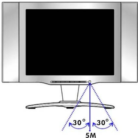
Your remote control can be activated from up to 5m away, if pointed directly in front of the device.
text_image
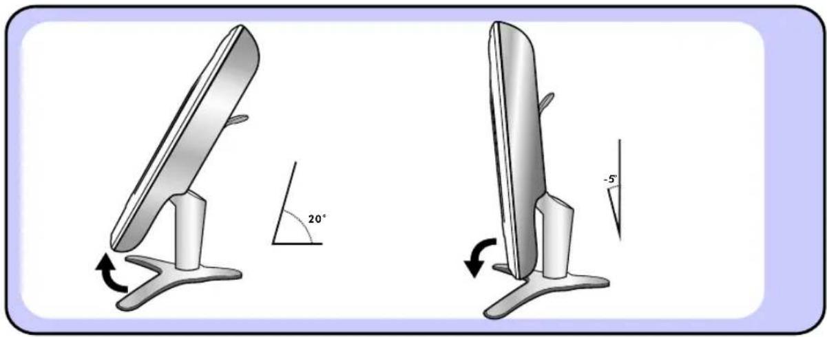
30° 30° 5MYou may adjust the angle of the LCD TV about 25 degrees.
natural_image
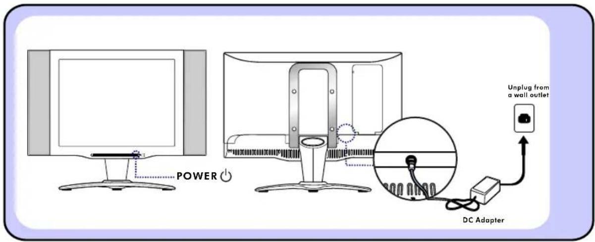
Illustration of two computer monitors with directional arrows indicating rotation, showing 20° and -5° angle orientations (no text or symbols on the devices themselves)2 Always turn the LCD TV off when the LCD TV is not in use for a long period of time. The Power button is only used for switching the LCD TV on and off, it does not disconnect the device from the main voltage.
To completely disconnect the main voltage, please remove the power plug from the socket.
text_image
POWER Unplug from a wall outlet DC AdapterINSTALLATION
Refer to the owner's manual of the external equipments to be connected. When connecting an external equipment, do not connect any AC power cords to wall outlets until you have completed all connections.
Connecting a TV Cable or an Antenna
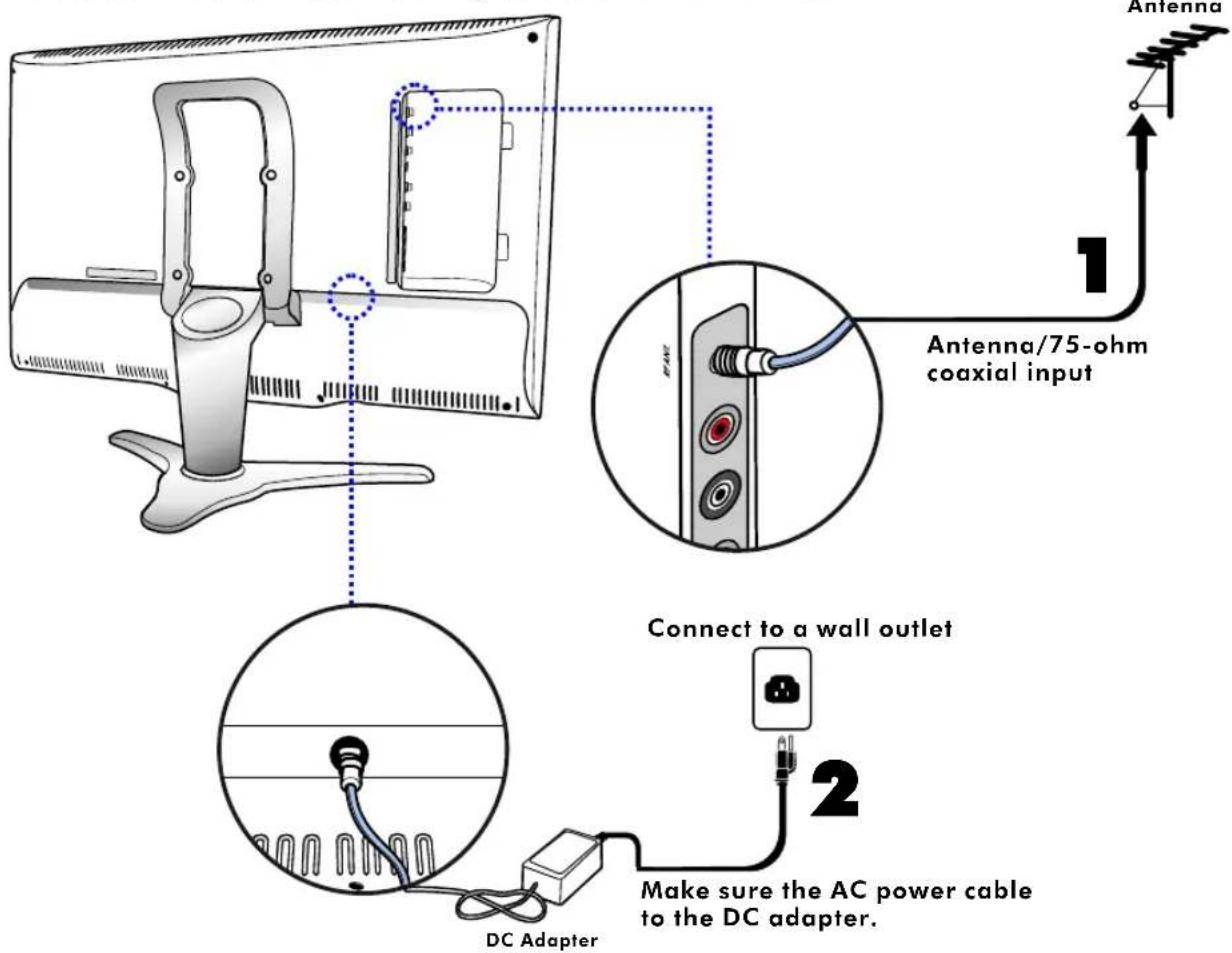
Basic Connection: Connecting cable or an antenna.
text_image
Antenna 1 Antenna/75-ohm coaxial input Connect to a wall outlet 2 Make sure the AC power cable to the DC adapter. DC Adapter1 Use a supplied antenna cable to connect the VHF/UHF to your LCD TV.
2 Connect the AC power cable to the DC adapter and connect the adapter to the power jack on the back of your LCD TV.
3 Press the POWER button on the remote to turn on your LCD TV.
4 Press the TV button on the remote to view.
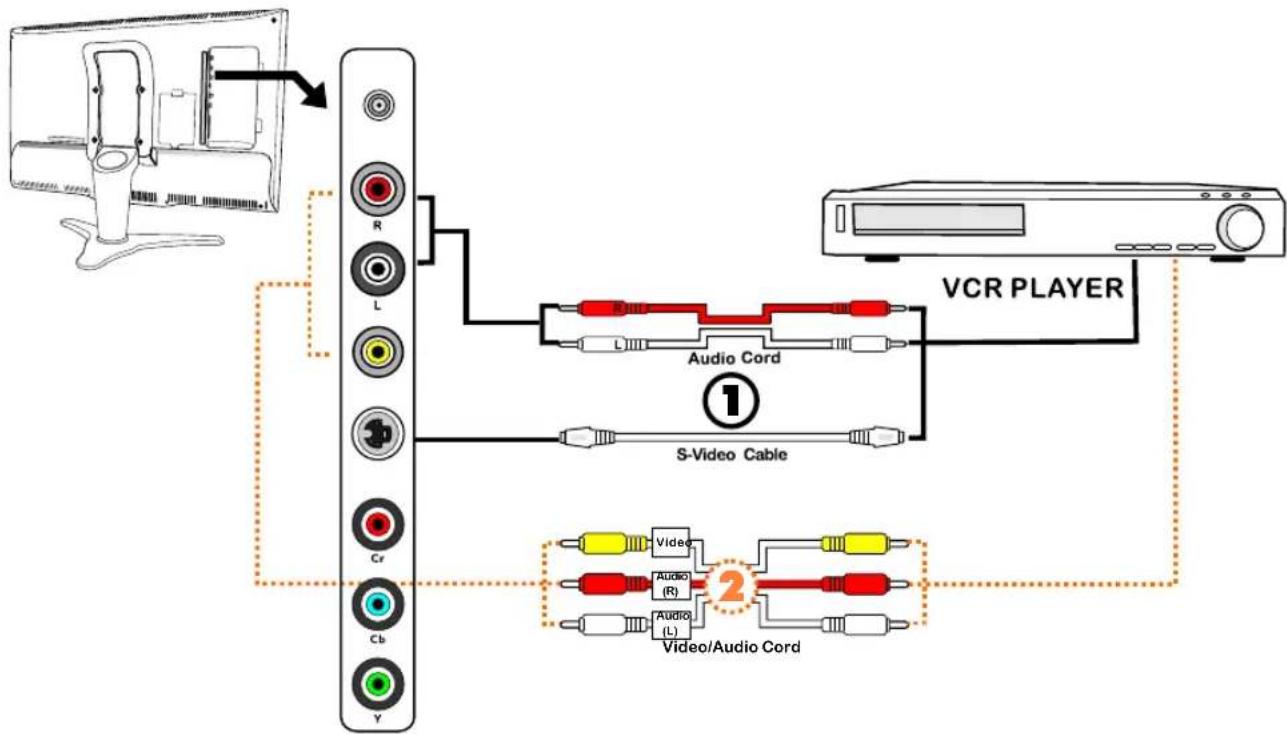
Connecting a VCR
flowchart
graph TD
    A["Computer monitor with cable"] --> B["Switch"]
    B --> C["Audio Cord 1"]
    C --> D["VCR PLAYER"]
    D --> E["Video/Audio Cord 2"]
    E --> F["Audio (R)"]
    E --> G["Audio (L)"]
    E --> H["Audio (R)"]
    E --> I["Audio (L)"]
    style A fill:#f9f,stroke:#333
    style B fill:#ccf,stroke:#333
    style C fill:#cfc,stroke:#333
    style D fill:#fcc,stroke:#333
    style E fill:#cff,stroke:#333
    style F fill:#ffc,stroke:#333
    style G fill:#ffc,stroke:#333
    style H fill:#ffc,stroke:#333
    style I fill:#ffc,stroke:#333
Method 1 :
1 Use an Audio cable to connect the VCR s audio output jacks to your LCD TV. Use an S-Video cable to connect your LCD TV and VCR player.
2 Connect the AC power cable to the DC adapter and connect the adapter to the power jack on the back of your LCD TV.
3 Press the POWER button on the remote to turn on your LCD TV.
4 To watch VCR, press the S-VIDEO button on the remote.
Method 2 :
1 Use an AV cable to connect the VCR s composite output jacks to your LCD TV.
2 Connect the AC power cable to the DC adapter and connect the adapter to the power jack on the back of your LCD TV.
3 Press the POWER button on the remote to turn on your LCD TV.
4 To watch VCR, press the AV button on the remote.
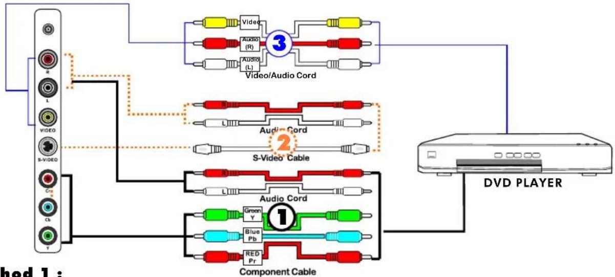
Connecting a DVD Player
For best picture quality, if your equipment has component video output, use component cable instead of a standard video or S-video cable.
flowchart
graph TD
    A["S-VIDEO"] --> B["Component Cable"]
    A --> C["Audio Cord"]
    A --> D["Video/Audio Cord"]
    A --> E["Video"]
    A --> F["Blue Pb"]
    A --> G["Red Pr"]
    B --> H["DVD PLAYER"]
    C --> H
    D --> H
    E --> H
    F --> H
    G --> H
    style A fill:#f9f,stroke:#333
    style B fill:#ccf,stroke:#333
    style C fill:#cfc,stroke:#333
    style D fill:#fcc,stroke:#333
    style E fill:#cff,stroke:#333
    style F fill:#ffc,stroke:#333
    style G fill:#cfc,stroke:#333
Method 1 :
1 Use a component cable to connect the Y, Cb, and Cr jacks on the DVD player to your LCD TV. Use an audio cable to connect the DVD s audio jacks to your LCD TV.
2 Connect the AC power cable to the DC adapter and connect the adapter to the power jack on the back of your LCD TV.
3 Press the POWER button on the remote to turn on your LCD TV.
4 To watch DVD, press the YUV button on the remote.
Method 2 :
1 Use an Audio cable to connect the DVD s audio output jacks to your LCD TV. Use an S-Video cable to connect your LCD TV and DVD player.
2 Connect the AC power cable to the DC adapter and connect the adapter to the power jack on the back of your LCD TV.
3 Press the POWER button on the remote to turn on your LCD TV.
4 To watch DVD, press the S-VIDEO button on the remote.
Method 3 :
1 Use an AV cable to connect the DVD s composite output jacks to your LCD TV.
2 Connect the AC power cable to the DC adapter and connect the adapter to the power jack on the back of your LCD TV.
3 Press the POWER button on the remote to turn on your LCD TV.
4 To watch DVD, press the AV button on the remote.
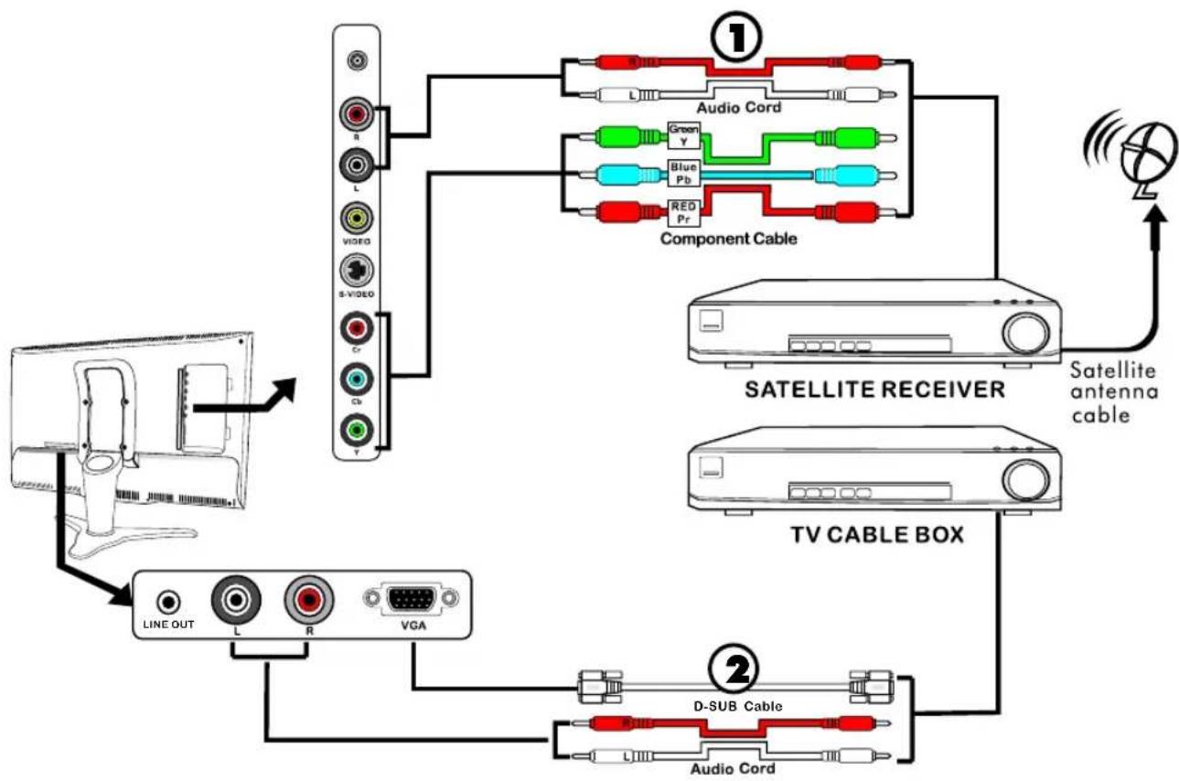
Connecting a TV Box and Satellite Receiver
flowchart
graph TD
    A["TV CABLE BOX"] --> B["SATELLITE RECEIVER"]
    B --> C["Component Cable"]
    C --> D["Audio Cord"]
    C --> E["D-SUB Cable"]
    D --> F["Satellite antenna cable"]
    E --> G["Audio Cord"]
    H["Computer"] --> I["Line OUT"]
    I --> J["L"]
    J --> K["R"]
    K --> L["VGA"]
    L --> M["Video"]
    M --> N["Cr"]
    N --> O["Gb"]
    O --> P["Y"]
    P --> Q["L"]
    Q --> R["Radio"]
    R --> S["Satellite Antenna Cable"]
1 Use a component cable to connect the Y/Cb/Cr jacks on the satellite receiver to your LCD TV. Use an Audio cable to connect the Satellite Receiver audio jacks to LCD TV.
2 Use a D-SUB cable to connect the TV Cable Box D-SUB(VGA) connector to your LCD TV. Use an audio cable to connect the LCD TV and TV Cable Box.
3 Connect the AC power cable to the DC adapter and connect the adapter to the power jack on the back of your LCD TV.
4 Press the POWER button on the remote to turn on your LCD TV.
5 To watch programs by satellite receiver, press the YUV button on the remote.
6 To watch TV by TV cable box, press the VGA button on the remote.
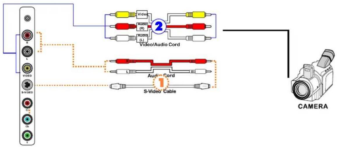
Connecting a Video Camera
text_image
R L VIDEO S-VIDEO Cra Cb Y Video Audio (R) Audio (L) Video/Audio Cord 2 Audio Cord S-Video Cable CAMERAMethod 1 :
1 Use an Audio cable to connect the Video Camera s audio output jacks to your LCD TV. Use an S-Video cable to connect your LCD TV and video camera.
2 Connect the AC power cable to the DC adapter and connect the adapter to the power jack on the back of your LCD TV.
3 Press the POWER button on the remote to turn on your LCD TV.
4 To watch your video camera, press the S-VIDEO button on the remote.
Method 2 :
1 Use an AV cable to connect the Video Camera's composite output jacks to your LCD TV.
2 Connect the AC power cable to the DC adapter and connect the adapter to the power jack on the back of your LCD TV.
3 Press the POWER button on the remote to turn on your LCD TV.
4 To watch your video camera, press the AV button on the remote.
Note:
Not all cameras have the ability to connect to a TV. Please check your video camera user guide for compatibility.
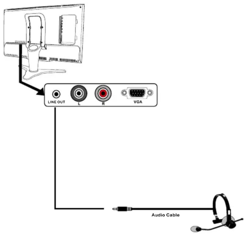
Connecting an Ear Phone
text_image
LINE OUT L R VGA Audio Cable1 Connect the LCD TV's LINE output jack to the Ear phone.
2 Connect the AC power cable to the DC adapter and connect the adapter to the power jack on the back of your LCD TV.
3 Press the POWER button on the remote to turn on your LCD TV.
USING THE FEATURES
Setting up the Channel List
flowchart
graph TD
    A["MENU"] --> B["VIDEO ADJUSTMENT"]
    A --> C["PC DISPLAY"]
    A --> D["TV SETTING"]
    D --> E["C.C/V-CHIP"]
    D --> F["AUDIO SETUP"]
    D --> G["SETUP MENU"]
    D --> H["RESET"]
    D --> I["EXIT"]
    J["TV SETTING"] --> K["SOURCE"]
    J --> L["CABLE STD"]
    J --> M["CH SEARCH"]
    J --> N["CH MEMORY"]
    J --> O["NO"]
    J --> P["RETURN"]
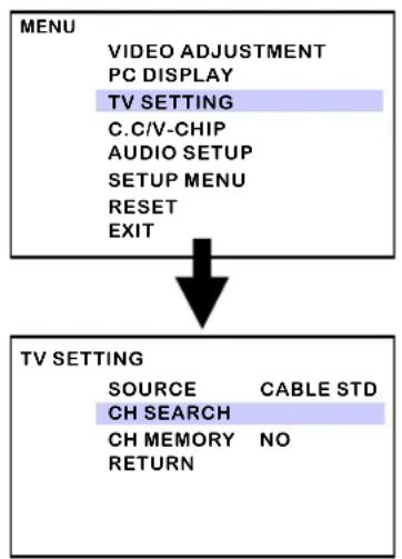
1 After you have finished connecting a TV cable or antenna to your LCD TV, press the TV button on the remote control.
2 Press the MENU button on the remote control to display the TV Menu, and use to select the TV SETTING, then press the OK button.
3 Press ◆ to move the highlight bar to the CH SEARCH, then press the OK button.
The CH SEARCH automatically creates a list of receivable channels
Press the EXIT button at any time to interrupt the memorization process. (the list cannot be created if interrupted) ..
Editing channels
Allow you to customize the channel list that appears when you use the CHANNEL+- buttons.
flowchart
graph TD
    A["MENU"] --> B["VIDEO ADJUSTMENT"]
    A --> C["PC DISPLAY"]
    A --> D["TV SETTING"]
    A --> E["C.C/V-CHIP"]
    A --> F["AUDIO SETUP"]
    A --> G["SETUP MENU"]
    A --> H["RESET"]
    A --> I["EXIT"]
    J["TV SETTING"] --> K["SOURCE"]
    J --> L["CABLE STD"]
    J --> M["CH SEARCH"]
    J --> N["CH MEMORY"]
    J --> O["NO"]
    J --> P["RETURN"]
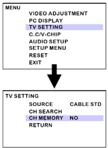
1 Press the CHANNEL+- button on the remote control to select the channel you wish to delete.
2 Press the MENU button on the remote control to display the TV Menu, and use to select the TV SETTING, then press the OK button.
3 Press 🔒 to select the CH MEMORY, then press the OK button.
4 Press ◆ to select the NO option to remove a channel. Repeat steps 1\~4 to remove other channels.
5 To add a channel, use the 0-9 buttons to choose the channel you wish to add and Press 🔊 to select the YES option, then repeat steps 2\~3 to add the channel.
You can also use to select the RESET option, then press the OK button to restore a default TV channel table.
Watching your LCD TV
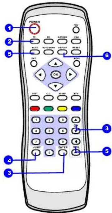
1 Press the POWER button to turn your LCD TV on.
2 Press the TV button to enter TV mode.
3 Press the CH▲▼ button to change channels, or use the 0-9 buttons to choose a channel, then press the ENTER button.
4 Press the JUMP button to alternate back and forth between two channels.
5 Press the VOL▲▼ button to adjust the volume.
Press the MUTE button to turn the sound off, press again to turn the sound on.
6 Press the DISPLAY button to display the information such as channel or channel label. Press the EXIT button again to hide the information.
text_image
POWER TV AV B-1/2000 FDA MUTL AUTODEM DISPLAY RESET EXIT MIND OK TEST C.C HSBF MTB 1 2 3 4 5 6 7 8 9 + JUMP ENTER VOL 1 2 3 3 5 4 3
natural_image
Blue silhouette of a cat sitting beside a palm tree, labeled 'TV' and '24' (no other text or symbols)If your LCD TV does not display a picture, check to make sure all connections are secure and correct.
Using the OSD
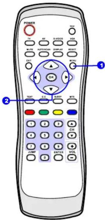
1 To select the signal source, press the MENU button on the remote control. The main menu will appear on the screen.
| MENU |
| VIDEO ADJUSTMENT |
| PC DISPLAY |
| TV SETTING |
| C.C/V-CHIP |
| AUDIO SETUP |
| SETUP MENU |
| RESET |
| EXIT |
2 Use 🔒 to highlight your main menu option, then press the OK button
to enter your selected option.
Use ◆ to highlight an option of the sub-menu. Use ◆ to change the value of the item.
Press the EXIT button to exit the OSD.
text_image
POWER TV AV S-VIDEO VGA WRITE AUTOMAN DISPLAY RESET EXIT OK MCMU TEXT G C SLEEP MTS 1 2 3 4 5 6 7 8 9 JUMP 0 ENTER VOL ① ②Viewing the OSD Chart
1
VIDEO ADJUSTMENT
Allows you to make adjustments to your picture settings
2
PC DISPLAY
Allows you to adjust the RGB color. This function will enable if the signal source is VGA.
3
TV SETTING
Allows you to edit and label channels, auto scan. This function will enable if the signal source is TV.
4
C.C /V-CHIP
Allows you to block the programs by TV ratings. This function will enable if the signal source is TV.
5
AUDIO SETUP
Allows you to customize the audio options and effects.
6
SETUP MENU
Allows you to set up the following features: OSD timeout, OSD language.
7
RESET
Allows you to restore the factory setting.
8
EXIT
Allows you to exit the OSD.
If the signal source is TV/C-VIDEO/S-VIDEO/YCbCr, the OSD displays:
VIDEO ADJUSTMENT
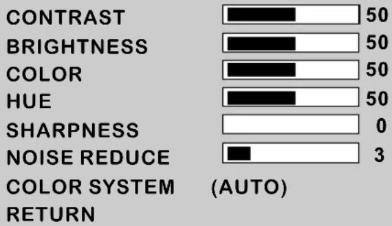
bar
| Category | Value | |---|---| | CONTRAST | 50 | | BRIGHTNESS | 50 | | COLOR | 50 | | HUE | 50 | | SHARPNESS | 0 | | NOISE REDUCE | 3 | COLOR SYSTEM (AUTO) RETURN2 The VIDEO ADJUSTMENT includes the following options:
Option Description
| CONTRAST | Allows you to adjust the contrast of the picture. |
| BRIGHTNESS | Allows you to adjust the brightness of the picture. |
| COLOR | Allows you to adjust the color intensity of the picture. |
| HUE | Allows you to adjust the color tint of the picture. |
| SHARPNESS | Allows you to adjust the sharpness of the picture. |
| NOISE REDUCE | If the receiving signal is weak and picture is blurry, you can adjust the level to improve the picture. |
| COLOR SYSTEM | Allows you to select TV system as NTSC, PAL or AUTO. |
| RETURN | Allows you to return to the previous menu. |
PC DISPLAY
1 If the signal source is VGA, the OSD displays:
PC DISPLAY

bar
| Category | Value | |---|---| | CONTRAST | 50 | | BRIGHTNESS | 50 | | CLOCK | 50 | | PHASE | 50 | | H-POSITION | 0 | | V-POSITION | 3 | AUTO CONFIGURE RETURN2 The PC DISPLAY includes the following options:
Option Description
| CONTRAST | Allows you to adjust the contrast of the picture. |
| BRIGHTNESS | Allows you to adjust the brightness of the picture. |
| CLOCK | Allows you to adjust the vertical size of the picture. |
| PHASE | Allows you to improve focus clarity and image stability. |
| H POSITION | Allows you to adjust the position of the picture left and right in the window. |
| V POSITION | Allows you to adjust the position of the picture up and down in the window. |
| COLOR | Allows you to customize color option as USER, WARM, or COOL. |
USER:
| R-GAIN | Allows you to adjust the amount of red tint in an image.. |
| G-GAIN | Allows you to adjust the amount of green tint in an image.. |
| B-GAIN | Allows you to adjust the amount of blue tint in an image.. |
AUTO CONFIGURE Allows you to auto adjust the display mode.
RETURN Allows you to return to the previous menu.
TV SETTING
1 If the signal source is TV, the OSD displays:
TV SETTING
| SOURCE | CABLE STD |
| CH SEARCH | |
| CH MEMORY | NO |
| RETURN |
2 The TV SETTING includes the following options:
Option Description
| SOURCE | Allows you to choose the antenna or cable signal.AIR: If you are receiving TV channels with an antenna.CABLE STD/HRC/IRC: If you are receiving TV channels with a CATV cable. |
| CH SEARCH | Allows you to automatically create a list of receivable channels |
| CH MEMORY | Allows you to add/remove channels. (Refer to page 25) |
| RETURN | Allows you to return to the previous menu. |
C.C/V-CHIP
If the signal source is TV, the OSD displays:
C.C /V-CHIP
MODE
INPUT SECRET NO.
RETURN
CC/T OFF
...
2 The C.C/V-CHIP includes the following options:
MODE (Close Caption Mode):
Allows you to select from 4 closed caption modes:
CC1\~CC4 : Displays a printed version of the dialog or sound effects of program.
TT1\~TT4: Displays station information, using either half or the whole screen.
V-CHIP function
1 Press the MENU button on the remote control to display the TV Menu, and use ⚠️ to select the C.C/V-CHIP, then press the OK button.
2 Press to move the highlight bar to the MODE, then press the OK button.
3 The factory password is 0 0 0 0. Enter the four-digit password then press the OK button, the V-CHIP SETUP displays.
4 Press to move the highlight bar to the V-CHIP, then select ON to enable the V-CHIP function.
The U.S has 2 rating systems for viewing content: MPAA Rating and TV Rating.
The TV Rating works in conjunction with the V-CHIP to help parents block inappropriate programs from their children.
The MPAA Rating is used for original movies rated by the Motion Picture Association of America (MPAA) as watched on cable TV and not edited for television.
TV Rating
Age-Based Ratings
| Rating | Description |
| Y | All children |
| Y7 | Directed to children age 7 and older |
| G | General Audience |
| PG | Parents Guidance suggested |
| 14 | Parents strongly cautioned |
| MA | Mature Audience only |
1 Press ◆ to select the rating you want and press the OK Button, press the OK button again to unlock.(B: blcked, U: Unblocked)
2 Press the EXIT button to return to the V-CHIP SETUP.
MPAA Rating
| Rating Description | |
| G | General Audiences. Movie is appropriate for all ages. |
| PG | Parental guidance suggested. May Contain material not suited for younger viewers. |
| PG-13 | Contains content that may not be appropriate for viewers under the ages of 13. |
| R | Restricted. Contains adult content, no one under 17 admitted without parent. |
| NC-17 | No one 17 and under admitted. |
| X | No one 17 and under admitted. |
1 Press 🔒 to select the rating you want and press the OK Button, press the OK button again to unlock.(B: blcked, U: Unblocked)
2 Press the EXIT button to return to the V-CHIP SETUP.
Change PIN
1 Use 0-9 on the remote control to enter a new four-digit password and press the OK button.
AUDIO SETUP
If the signal source is TV/C-VIDEO/YCbCr/S-VIDEO/VGA, the OSD displays:
AUDIO SETUP
BASS
TREBLE
BALANCE
BBE
MUTE
RETURN
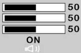
text_image
50 50 50 ON2 The AUDIO SETUP includes the following options:
Option Description
| BASS | Allows you to adjust the lower-pitched sounds. |
| TREBLE | Allows you to adjust the higher-pitched sounds. |
| BALANCE | Allows you to adjust the balance of the speakers. |
| BBE | Allows you to turn the surround sound on or off (for stereo programs only).BBE (Barcus-Bery Electronics): BBE recreates the natural sound and improves sound clarity |
| MUTE | Allows you to mute the sound. |
| RETURN | Allows you to return to the previous menu. |
1 If the signal source is TV/C-VIDEO/YCbCr/S-VIDEO/VGA, the OSD displays:
SETUP MENU
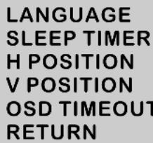
text_image
LANGUAGE SLEEP TIMER H POSITION V POSITION OSD TIMEOUT RETURN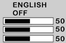
text_image
ENGLISH OFF 50 50 502 The OSD SETUP includes the following options:
Option Description
| LANGUAGE | Allows you to select a language for all the on-screen menu. |
| SLEEP TIMER | Allows you to set up a remaining time before the TV shuts off automatically : Off/0~120 mins. |
| H-POSITION | Allow syou to move the OSD position horizontally. |
| V-POSITION | Allows you to move the OSD position vertically. |
| OSD TIMEOUT | Allows you to set up the display time of the on-screen menu : 5~60 seconds and off. |
| RETURN | Allows you to return to the previous menu. |
TROUBLESHOOTING
Before consulting service personnel, check the following chart for a possible cause of the trouble you are experiencing and for a solution.
| PROBLEM | SOLUTION |
| TV will not turn on | Make sure the power cord is securely connected to the TV, DC adapter, and wall outlet.The batteries in the remote control may be exhausted.Replace the batteries. |
| No picture, no sound | Check the interface cable between TV and antenna/cable TV.Make sure the power cord is securely connected to the TV, DC adapter, and wall outlet.Press thePowerbutton on the remote.Press theTVbutton on the remote, or press other input source button to select the connected video sources. |
| Poor picture, sound OK | Check the interface cable between TV and antenna/cable TV.Try another channel, the station may have broadcast difficulties.Adjust the Brightness/Contrast options in the VIDEO ADJUSTMENT. |
| Picture OK, Poor sound | Sound may be muted. Press theMUTEbutton on the remote.Press theTVbutton on the remote, then press theVOL+button to increase the volume. |
| Audio noise | Move any infrared equipment away from the TV. |
SPECIFICATION
| Model | HV-147 |
| Panel System | 14 Inch LCD TV |
| Display Resolution | 640 pixels(horizontal) x 480 pixels (vertical) |
| Television System | NTSC/PAL-D/K |
| Antenna Input | 75 Ω unbalanced |
| Inputs /Outputs | |
| Composite Video In | 1 |
| S-Video In | 1 |
| Component In | 1 |
| D-SUB | 1 |
| Audio In | 2 |
| Ear Phone | 1 |
| Speaker Out | 3W x 2 |
| Power Source | |
| Power Consumption (MAX) | AC 100-240V, 60/50 HZ, 60W |
| Dimension(Physical) | 18.58 inch (W) x14.61 inch (H) x 8.91 inch (D) |
| Weight(Net) | 10.79 lbs |
PROVIEW Experience the Difference
Your Proview Plasma/LCD Display will be repaired or replaced in accordance with the terms of this warranty, at Proview's option, if it proves to be defective in material or workmanship under normal use, during the warranty period (Warranty Period) listed below, effective from the date (Date of Purchase) of original consumer purchase of the product. This warranty is good only to the original purchaser of the product and effective only when used in the United States, including Alaska, Hawaii, and U.S. Territories.
WARRANTY PERIOD:
■ LABOR and PARTS: 1 YEAR from the Date of Purchase. Your unit will be repaired or replaced with a new, substitute model or factory reconditioned unit, at Proview's option. If repaired, parts used in the repair may be new or remanufactured. Replacement Units and Repair Parts are warranted for the remaining portion of the original unit's warranty period.
■ EFFECTIVE DATE OF WARRANTY: Your warranty period begins on the date of sale to the original consumer/end user. KEEP THE DATED BILL OF SALE OR PROOF OF DELIVERY as evidence of the purchase date. You will be required to submit a legible copy of your bill of sale or proof of delivery when requesting warranty service.
THIS WARRANTY IS IN LIEU OF ANY OTHER WARRANTY, EXPRESS OR IMPLIED, INCLUDING WITHOUT LIMITATION, ANY WARRANTY OF MERCHANTABILITY OR FITNESS FOR A PARTICULAR PURPOSE. TO THE EXTENT ANY IMPLIED WARRANTY IS REQUIRED BY LAW, IT IS LIMITED IN DURATION TO THE EXPRESSED WARRANTY PERIOD ABOVE. NEITHER THE MANUFACTURER NOR ITS U.S. DISTRIBUTOR SHALL BE LIABLE FOR ANY INCIDENTAL, CONSEQUENTIAL, INDIRECT, SPECIAL, OR PUNITIVE DAMAGES OF ANY NATURE, INCLUDING WITHOUT LIMITATION, LOST PROFITS, LOST OR CORRUPTED PROGRAMMING OR DATA, OR ANY OTHER DAMAGE WHETHER BASED IN CONTRACT, TORT, OR OTHERWISE.
Some states do not allow the exclusion or limitation of incidental or consequential damages or limitations on how long an implied warranty lasts, so the above exclusion or limitation may not apply to you. This warranty gives you specific legal rights and you may also have other rights that vary from state to state.
CONCERNING PIXEL FUNCTIONALITY: Your Plasma/LCD Television contains about one million individual pixels. These Televisions typically contain a small number of pixels that do not function normally. Your display has been inspected and is in compliance with manufacturer's specifications, indicating that any pixel defects do not effect the operation or use of your display.
THIS LIMITED WARRANTY DOES NOT APPLY TO:
■ Damage caused in shipping or transit
■ Image burn-in (Plasma Only)
■ Service required as a result of improper installation, including incorrect or insufficient AC supply (please consult the owner's manual for power supply requirements)
■ Installation or repair of antenna systems, cable converters, cable company supplied equipment, or other components in a video system
■ Setup or adjustment on consumer controls, or damage caused by improper adjustments
■ Damage caused by other system components
■ Any panel that has been modified or incorporated into any other product
■ Replacement of batteries on the remote control
■ Damage (including cosmetic damage), failure, loss or personal injury due to misuse, abuse, negligence, improper maintenance or storage, or to acts of nature or other causes beyond our control. (Causes beyond our control include but are not limited to lightning strike, power surges, power outages and water damage.)
■ Repair or replacement of warranted parts by other than Proview authorized service centers.
■ Units purchased or serviced outside of the coverage area.
■ Product where the original factory serial numbers have been removed defaced or changed in any way.
■ Product sold and labeled as as is, where is or similar disclaimer.
The cost of repair or replacement under these excluded circumstances shall be borne by the consumer. FOR SERVICE:
Before you call for warranty service, check your operating guide under the troubleshooting section, this may help you avoid a service call. For warranty service information, please contact the Proview Customer Interactive Center telephone number (see below). When calling for service, please have your product model number, serial number and the date of purchase or the date of original installation available. If a replacement unit is required, under some circumstances you may be asked to provide a reserve deposit to the Proview Service Center against a credit card number as surety for advanced shipment. Your credit card will not be charged if you return the defective unit within 30 working days. If a replacement unit is received, please use the carton and packaging from that unit in returning the defective unit to the Proview Brand Service Center. Parts and service in accordance with the Proview warranty are Proview's responsibility and will be provided without charge. Other service requirements will be at the owner's expense. If you have problems in obtaining satisfactory warranty service, write or call the Proview Customer Interactive Center. Service may be provided by independently owned and operated service organizations. To assure proper credit and avoid unnecessary charges, you must obtain a Proview Return Authorization before returning any product to the Proview Service Center. Contact the Customer Interactive Center for details. In-Home Service (for screen sizes over 20 only): Please retain dated bill of sale or delivery ticket as evidence of the Date of Purchase for proof of warranty, and submit a copy of the bill of sale to the service person at the time warranty service is provided.
Please call (877 532-8176) to locate you're nearest
Proview Authorized Service Center, or
Visit our website at:
Http://www.proview.net/service/index.htm
CONTACT THE PROVIEW CUSTOMER SERVICE CENTER BY TELEPHONE OR MAIL:
To obtain customer assistance, product information or Service locations by phone:
(877 532-8176), MonFri 7am8 pm CT and Sat 8am5 pm CT
To obtain customer assistance, product information or Service locations by Mail:
Proview Customer Interactive Center
P.O. Box 192
Lincolnshire, IL, 60069-9998
IMPORTANT PRODUCT REGISTRATION INFORMATION:
It is important to register this or any Proview product. Registering will allow us to reach you promptly should we discover a safety or reliability issue that can affect your product. To register please visit www.proview.net/service/ce/reg.htm and fill in your information. Registration is completely optional. Failure to register this product will not affect your warranty. Your Proview product will be repaired or replaced in accordance with the terms of this warranty, at the option of Proview, if it proves to be defective in material or workmanship under normal use and conditions during the warranty period ('warranty period') listed below effective from the date of original consumer purchase of the product ('date of purchase'). This warranty is good only to the original purchaser of the product and effective only when used in the United States, including Alaska, Hawaii and U.S. Territories.