
Inspiron 3481 - Laptop DELL - Free user manual and instructions
Find the device manual for free Inspiron 3481 DELL in PDF.


User questions about Inspiron 3481 DELL
0 question about this device. Answer the ones you know or ask your own.
Ask a new question about this device
Download the instructions for your Laptop in PDF format for free! Find your manual Inspiron 3481 - DELL and take your electronic device back in hand. On this page are published all the documents necessary for the use of your device. Inspiron 3481 by DELL.
USER MANUAL Inspiron 3481 DELL
Notes, cautions, and warnings
NOTE: A NOTE indicates important information that helps you make better use of your product.
CAUTION: A CAUTION indicates either potential damage to hardware or loss of data and tells you how to avoid the problem.
WARNING: A WARNING indicates a potential for property damage, personal injury, or death.
Contents
Chapter 1: Before working inside your computer....8
Before you begin 8
Chapter 2: After working inside your computer....9
Chapter 3: Safety instructions....10
Electrostatic discharge—ESD protection....10
ESD field service kit 11
Transporting sensitive components....12
Chapter 4: Recommended tools....13
Chapter 5: Screw list....14
Chapter 6: Removing the base cover....16
Procedure....16
Chapter 7: Replacing the base cover.... 18
Procedure....18
Chapter 8: Removing the battery....21
Lithium-ion battery precautions....21
Prerequisites....21
Procedure....21
Chapter 9: Replacing the battery....23
Procedure....23
Post-requisites....23
Chapter 10: Removing the memory modules....24
Prerequisites....24
Procedure....24
Chapter 11: Replacing the memory modules....26
Procedure....26
Post-requisites....26
Chapter 12: Removing the wireless card....27
Prerequisites....27
Procedure....27
Chapter 13: Replacing the wireless card....29
Procedure....29
Post-requisites....30
Chapter 14: Removing the coin-cell battery....31
Prerequisites....31
Procedure....31
Chapter 15: Replacing the coin-cell battery....32
Procedure....32
Post-requisites....32
Chapter 16: Removing the fan.... 33
Prerequisites....33
Procedure....33
Chapter 17: Replacing the fan....34
Procedure....34
Post-requisites....34
Chapter 18: Removing the heat sink....35
Prerequisites.... 35
Procedure....35
Chapter 19: Replacing the heat sink....37
Procedure 37
Post-requisites....37
Chapter 20: Removing the solid-state drive/Intel Optane memory module.... 38
Prerequisites....38
Procedure....38
Chapter 21: Replacing the solid-state drive/Intel Optane memory module....40
Procedure 40
Post-requisites....41
Chapter 22: Removing the hard drive....42
Prerequisites....42
Procedure....42
Chapter 23: Replacing the hard drive....44
Procedure....44
Post-requisites....45
Chapter 24: Removing the touchpad....46
Prerequisites....46
Procedure....46
Chapter 25: Replacing the touchpad....48
Procedure....48
Post-requisites....49
Chapter 26: Removing the speakers....50
Prerequisites....50
Procedure....50
Chapter 27: Replacing the speakers....51
Procedure....51
Post-requisites....51
Chapter 28: Removing the I/O board....52
Prerequisites....52
Procedure....52
Chapter 29: Replacing the I/O board....53
Procedure 53
Post-requisites....53
Chapter 30: Removing the display assembly....54
Prerequisites....54
Procedure....54
Chapter 31: Replacing the display assembly....57
Procedure 57
Post-requisites....58
Chapter 32: Removing the power-button board....59
Prerequisites....59
Procedure....59
Chapter 33: Replacing the power-button board....60
Procedure 60
Post-requisites....60
Chapter 34: Removing the system board....61
Prerequisites....61
Procedure....61
Chapter 35: Replacing the system board....64
Procedure 64
Post-requisites....65
Entering the Service Tag in the BIOS setup program....65
Chapter 36: Removing the power button with fingerprint reader....67
Prerequisites....67
Procedure....67
Chapter 37: Replacing the power button with fingerprint reader....69
Procedure 69
Post-requisites....69
Chapter 38: Removing the power-adapter port.... 71
Prerequisites....71
Procedure....71
Chapter 39: Replacing the power-adapter port....73
Procedure....73
Post-requisites....73
Chapter 40: Removing the palm-rest and keyboard assembly....75
Prerequisites....75
Procedure....75
Chapter 41: Replacing the palm-rest and keyboard assembly....77
Procedure....77
Post-requisites....77
Chapter 42: Removing the display bezel....79
Prerequisites....79
Procedure....79
Chapter 43: Replacing the display bezel....81
Procedure 81
Post-requisites....82
Chapter 44: Removing the camera....83
Prerequisites....83
Procedure....83
Chapter 45: Replacing the camera....84
Procedure 84
Post-requisites....84
Chapter 46: Removing the display panel....85
Prerequisites....85
Procedure....85
Chapter 47: Replacing the display panel....87
Procedure 87
Post-requisites....88
Chapter 48: Removing the display hinges....89
Prerequisites....89
Procedure....89
Chapter 49: Replacing the display hinges....90
Procedure 90
Post-requisites....90
Chapter 50: Removing the display cable....91
Prerequisites....91
Procedure....91
Chapter 51: Replacing the display cable....93
Procedure....93
Post-requisites....93
Chapter 52: Removing the display back-cover and antenna assembly....95
Prerequisites....95
Procedure....95
Chapter 53: Replacing the display back-cover and antenna assembly....96
Procedure....96
Post-requisites....96
Chapter 54: Device drivers....97
Intel Chipset Software Installation Utility 97
Video drivers....97
Intel Serial IO driver....97
Intel Trusted Execution Engine Interface....97
Intel Virtual Button driver....97
Wireless and Bluetooth drivers....97
Chapter 55: System setup....98
System setup....98
Entering BIOS setup program....98
Navigation keys....98
Boot Sequence....98
System setup options....99
Clearing CMOS settings....103
Clearing BIOS (System Setup) and System passwords....104
Chapter 56: Troubleshooting....105
Flashing the BIOS....105
Flashing BIOS (USB key)....105
Enhanced Pre-Boot System Assessment (ePSA) diagnostics....105
Running the ePSA diagnostics....106
System diagnostic lights....106
Enabling Intel Optane memory....107
Disabling Intel Optane memory....107
WiFi power cycle....107
Flea power release....108
Before working inside your computer
NOTE: The images in this document may differ from your computer depending on the configuration you ordered.
Before you begin
- Save and close all open files and exit all open applications.
- Shut down your computer. Click Start > ⏻ Power > Shut down.
NOTE: If you are using a different operating system, see the documentation of your operating system for shut-down instructions.
- Disconnect your computer and all attached devices from their electrical outlets.
- Disconnect all attached network devices and peripherals, such as keyboard, mouse, and monitor from your computer.
- Remove any media card and optical disc from your computer, if applicable.
After working inside your computer

CAUTION: Leaving stray or loose screws inside your computer may severely damage your computer.
- Replace all screws and ensure that no stray screws remain inside your computer.
- Connect any external devices, peripherals, or cables you removed before working on your computer.
- Replace any media cards, discs, or any other parts that you removed before working on your computer.
- Connect your computer and all attached devices to their electrical outlets.
- Turn on your computer.
Safety instructions
Use the following safety guidelines to protect your computer from potential damage and ensure your personal safety.
NOTE: Before working inside your computer, read the safety information that shipped with your computer. For more safety best practices, see the Regulatory Compliance home page at www.dell.com/regulatory_compliance.
NOTE: Disconnect all power sources before opening the computer cover or panels. After you finish working inside the computer, replace all covers, panels, and screws before connecting to the electrical outlet.
CAUTION: To avoid damaging the computer, ensure that the work surface is flat and clean.
CAUTION: To avoid damaging the components and cards, handle them by their edges, and avoid touching pins and contacts.
CAUTION: You should only perform troubleshooting and repairs as authorized or directed by the Dell technical assistance team. Damage due to servicing that is not authorized by Dell is not covered by your warranty. See the safety instructions that shipped with the product or at www.dell.com/regulatory_compliance.
CAUTION: Before touching anything inside your computer, ground yourself by touching an unpainted metal surface, such as the metal at the back of the computer. While you work, periodically touch an unpainted metal surface to dissipate static electricity, which could harm internal components.
CAUTION: When you disconnect a cable, pull on its connector or on its pull tab, not on the cable itself. Some cables have connectors with locking tabs or thumb-screws that you must disengage before disconnecting the cable. When disconnecting cables, keep them evenly aligned to avoid bending any connector pins. When connecting cables, ensure that the ports and connectors are correctly oriented and aligned.
CAUTION: Press and eject any installed card from the media-card reader.
Electrostatic discharge—ESD protection
ESD is a major concern when you handle electronic components, especially sensitive components such as expansion cards, processors, memory DIMMs, and system boards. Very slight charges can damage circuits in ways that may not be obvious, such as intermittent problems or a shortened product life span. As the industry pushes for lower power requirements and increased density, ESD protection is an increasing concern.
Due to the increased density of semiconductors used in recent Dell products, the sensitivity to static damage is now higher than in previous Dell products. For this reason, some previously approved methods of handling parts are no longer applicable.
Two recognized types of ESD damage are catastrophic and intermittent failures.
- Catastrophic – Catastrophic failures represent approximately 20 percent of ESD-related failures. The damage causes an immediate and complete loss of device functionality. An example of catastrophic failure is a memory DIMM that has received a static shock and immediately generates a "No POST/No Video" symptom with a beep code emitted for missing or nonfunctional memory.
- Intermittent – Intermittent failures represent approximately 80 percent of ESD-related failures. The high rate of intermittent failures means that most of the time when damage occurs, it is not immediately recognizable. The DIMM receives a static shock, but the tracing is merely weakened and does not immediately produce outward symptoms related to the damage. The weakened trace may take weeks or months to melt, and in the meantime may cause degradation of memory integrity, intermittent memory errors, etc.
The more difficult type of damage to recognize and troubleshoot is the intermittent (also called latent or "walking wounded") failure.
Perform the following steps to prevent ESD damage:
- Use a wired ESD wrist strap that is properly grounded. The use of wireless anti-static straps is no longer allowed; they do not provide adequate protection. Touching the chassis before handling parts does not ensure adequate ESD protection on parts with increased sensitivity to ESD damage.
-
Handle all static-sensitive components in a static-safe area. If possible, use anti-static floor pads and workbench pads.
-
When unpacking a static-sensitive component from its shipping carton, do not remove the component from the anti-static packing material until you are ready to install the component. Before unwrapping the anti-static packaging, ensure that you discharge static electricity from your body.
- Before transporting a static-sensitive component, place it in an anti-static container or packaging.
ESD field service kit
The unmonitored Field Service kit is the most commonly used service kit. Each Field Service kit includes three main components: anti-static mat, wrist strap, and bonding wire.
Components of an ESD field service kit
The components of an ESD field service kit are:
- Anti-Static Mat – The anti-static mat is dissipative and parts can be placed on it during service procedures. When using an anti-static mat, your wrist strap should be snug and the bonding wire should be connected to the mat and to any bare metal on the system being worked on. Once deployed properly, service parts can be removed from the ESD bag and placed directly on the mat. ESD-sensitive items are safe in your hand, on the ESD mat, in the system, or inside a bag.
- Wrist Strap and Bonding Wire – The wrist strap and bonding wire can be either directly connected between your wrist and bare metal on the hardware if the ESD mat is not required, or connected to the anti-static mat to protect hardware that is temporarily placed on the mat. The physical connection of the wrist strap and bonding wire between your skin, the ESD mat, and the hardware is known as bonding. Use only Field Service kits with a wrist strap, mat, and bonding wire. Never use wireless wrist straps. Always be aware that the internal wires of a wrist strap are prone to damage from normal wear and tear, and must be checked regularly with a wrist strap tester in order to avoid accidental ESD hardware damage. It is recommended to test the wrist strap and bonding wire at least once per week.
- ESD Wrist Strap Tester – The wires inside of an ESD strap are prone to damage over time. When using an unmonitored kit, it is a best practice to regularly test the strap prior to each service call, and at a minimum, test once per week. A wrist strap tester is the best method for doing this test. If you do not have your own wrist strap tester, check with your regional office to find out if they have one. To perform the test, plug the wrist-strap's bonding-wire into the tester while it is strapped to your wrist and push the button to test. A green LED is lit if the test is successful; a red LED is lit and an alarm sounds if the test fails.
- Insulator Elements – It is critical to keep ESD sensitive devices, such as plastic heat sink casings, away from internal parts that are insulators and often highly charged.
- Working Environment – Before deploying the ESD Field Service kit, assess the situation at the customer location. For example, deploying the kit for a server environment is different than for a desktop or portable environment. Servers are typically installed in a rack within a data center; desktops or portables are typically placed on office desks or cubicles. Always look for a large open flat work area that is free of clutter and large enough to deploy the ESD kit with additional space to accommodate the type of system that is being repaired. The workspace should also be free of insulators that can cause an ESD event. On the work area, insulators such as Styrofoam and other plastics should always be moved at least 12 inches or 30 centimeters away from sensitive parts before physically handling any hardware components.
- ESD Packaging – All ESD-sensitive devices must be shipped and received in static-safe packaging. Metal, static-shielded bags are preferred. However, you should always return the damaged part using the same ESD bag and packaging that the new part arrived in. The ESD bag should be folded over and taped shut and all the same foam packing material should be used in the original box that the new part arrived in. ESD-sensitive devices should be removed from packaging only at an ESD-protected work surface, and parts should never be placed on top of the ESD bag because only the inside of the bag is shielded. Always place parts in your hand, on the ESD mat, in the system, or inside an anti-static bag.
- Transporting Sensitive Components – When transporting ESD sensitive components such as replacement parts or parts to be returned to Dell, it is critical to place these parts in anti-static bags for safe transport.
ESD protection summary
It is recommended that all field service technicians use the traditional wired ESD grounding wrist strap and protective anti-static mat at all times when servicing Dell products. In addition, it is critical that technicians keep sensitive parts separate from all insulator parts while performing service and that they use anti-static bags for transporting sensitive components.
Transporting sensitive components
When transporting ESD sensitive components such as replacement parts or parts to be returned to Dell, it is critical to place these parts in anti-static bags for safe transport.
Lifting equipment
Adhere to the following guidelines when lifting heavy weight equipment:

CAUTION: Do not lift greater than 50 pounds. Always obtain additional resources or use a mechanical lifting device.
- Get a firm balanced footing. Keep your feet apart for a stable base, and point your toes out.
- Tighten stomach muscles. Abdominal muscles support your spine when you lift, offsetting the force of the load.
- Lift with your legs, not your back.
- Keep the load close. The closer it is to your spine, the less force it exerts on your back.
- Keep your back upright, whether lifting or setting down the load. Do not add the weight of your body to the load. Avoid twisting your body and back.
- Follow the same techniques in reverse to set the load down.
Recommended tools
The procedures in this document may require the following tools:
- Philips screwdriver #1
- Flat-head screwdriver
- Plastic scribe
Screw list
NOTE: When removing screws from a component, it is recommended to note the screw type, the quantity of screws, and then place them in a screw storage box. This is to ensure that the correct number of screws and correct screw type is restored when the component is replaced.
NOTE: Some computers have magnetic surfaces. Ensure that the screws are not left attached to such surface when replacing a component.
NOTE: Screw color may vary with the configuration ordered.
Table 1. Screw list
| Component Secured to Screw type Quantity Screw | mage | |||
| Base cover Palm-rest and keyboard assembly | M2.5x4 6 | [5BW3] | ||
| Battery System board M2x5 4 | [5A07] | |||
| Display panel Display back-cover and antenna assembly | M2x2.5 4 |  | ||
| Fan System board M2x5 2 | [4Z70] | |||
| Hinges Palm-rest and keyboard assembly | M2.5x4 4 |  | ||
| Hinge brackets Display back-cover and antenna assembly | M2.5x2.5 6 | [H2A0] | ||
| Hinge brackets Display back-cover and antenna assembly | M2x2 2 |  | ||
| I/O board Palm-rest and keyboard assembly | M2x2 2 |  | ||
| Power-button Palm-rest and keyboard assembly | M2x3 2 |  | ||
| Power button with fingerprint reader (optional) | Palm-rest and keyboard assembly | M2x3 2 |  | |
| Solid-state drive System board M2x3 1 |  | |||
| System board Palm-rest and keyboard assembly | M2x2 6 |  | ||
| Touchpad | Palm-rest and keyboard assembly | M2x2 4 |  | |
| Touchpad (Support brackets) | Palm-rest and keyboard assembly | M2x2.5 2 |  | |
| Component Secured to S | crew type Quantity Screw | image | ||
| Wireless-card bracket I/O board M2x5 1 | pwcyn | |||
Removing the base cover

NOTE: Before working inside your computer, read the safety information that shipped with your computer and follow the steps in Before working inside your computer. After working inside your computer, follow the instructions in After working inside your computer. For more safety best practices, see the Regulatory Compliance home page at www.dell.com/regulatory_compliance.
Procedure
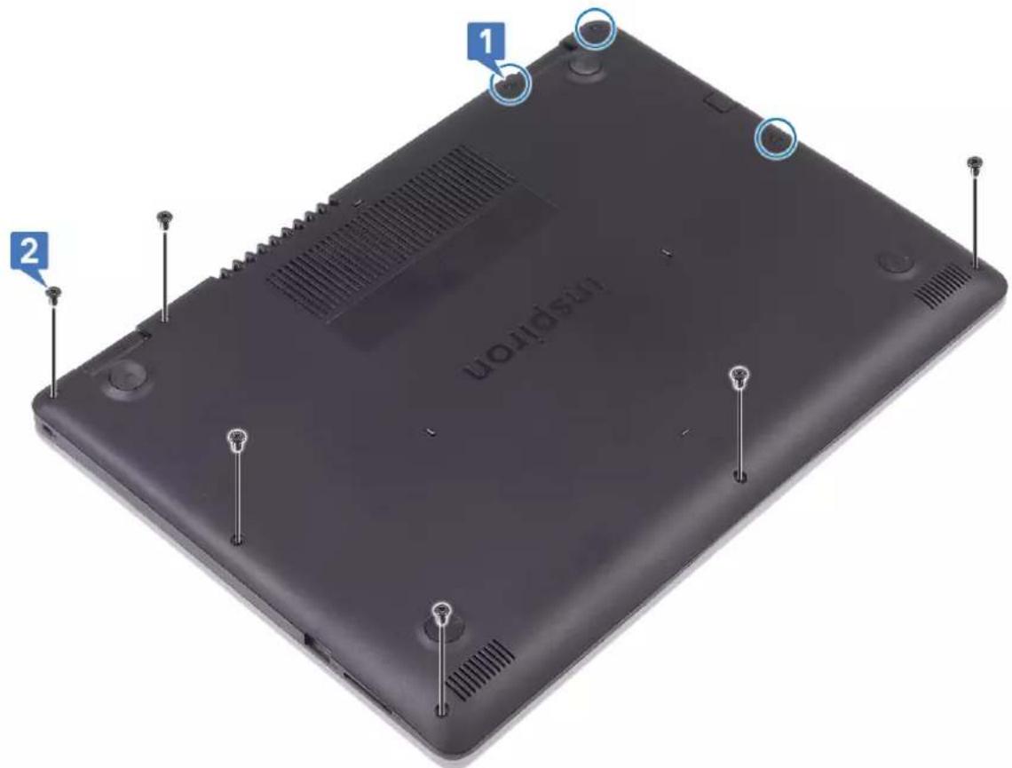
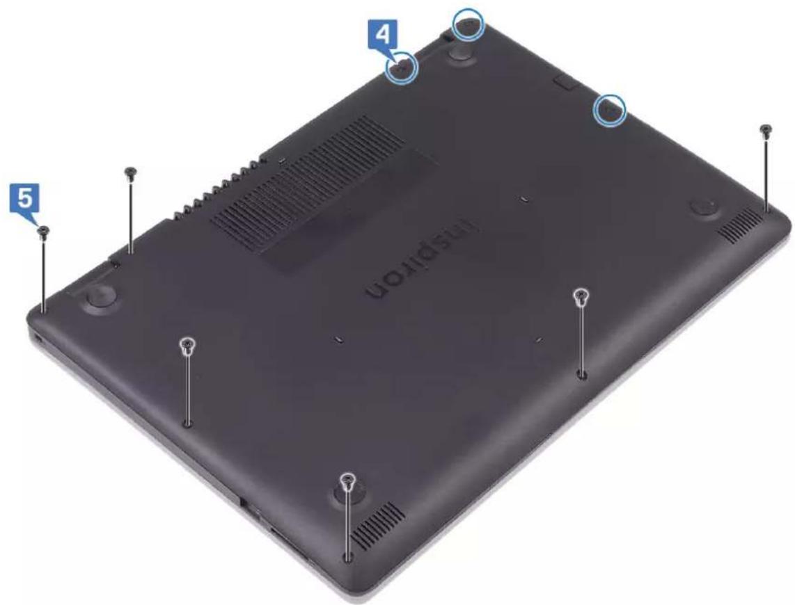
- Loosen the three captive screws on the base cover.
- Remove the six screws (M2.5x4) that secure the base cover to the palm-rest and keyboard assembly.
text_image
1 2 UOUPSUN-
Pry the base cover from the top-right corner of the palm-rest and keyboard assembly.
-
Lift the base cover off the palm-rest and keyboard assembly from the right side of the base cover.

text_image
3 4
NOTE: The following steps are applicable only if you want to further remove any other component from your computer.
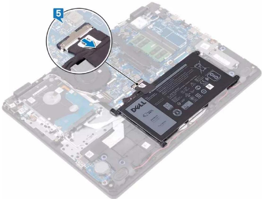
- Disconnect the battery cable from the system board.
natural_image
Disassembled laptop chassis with a Dell 42W6 battery and a close-up inset showing a cable being inserted (no text or symbols on the main components)- Press and hold the power button for 5 seconds to ground the computer and drain the flea power.
Replacing the base cover

NOTE: Before working inside your computer, read the safety information that shipped with your computer and follow the steps in Before working inside your computer. After working inside your computer, follow the instructions in After working inside your computer. For more safety best practices, see the Regulatory Compliance home page at www.dell.com/regulatory_compliance.
Procedure
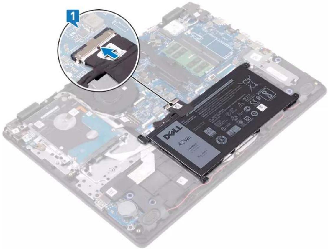
- Connect the battery cable to the system board, if applicable.

CAUTION: To avoid accidental damage to the power-adapter port, do not press the base cover against the power-adapter port when you snap the base cover to the computer base.
natural_image
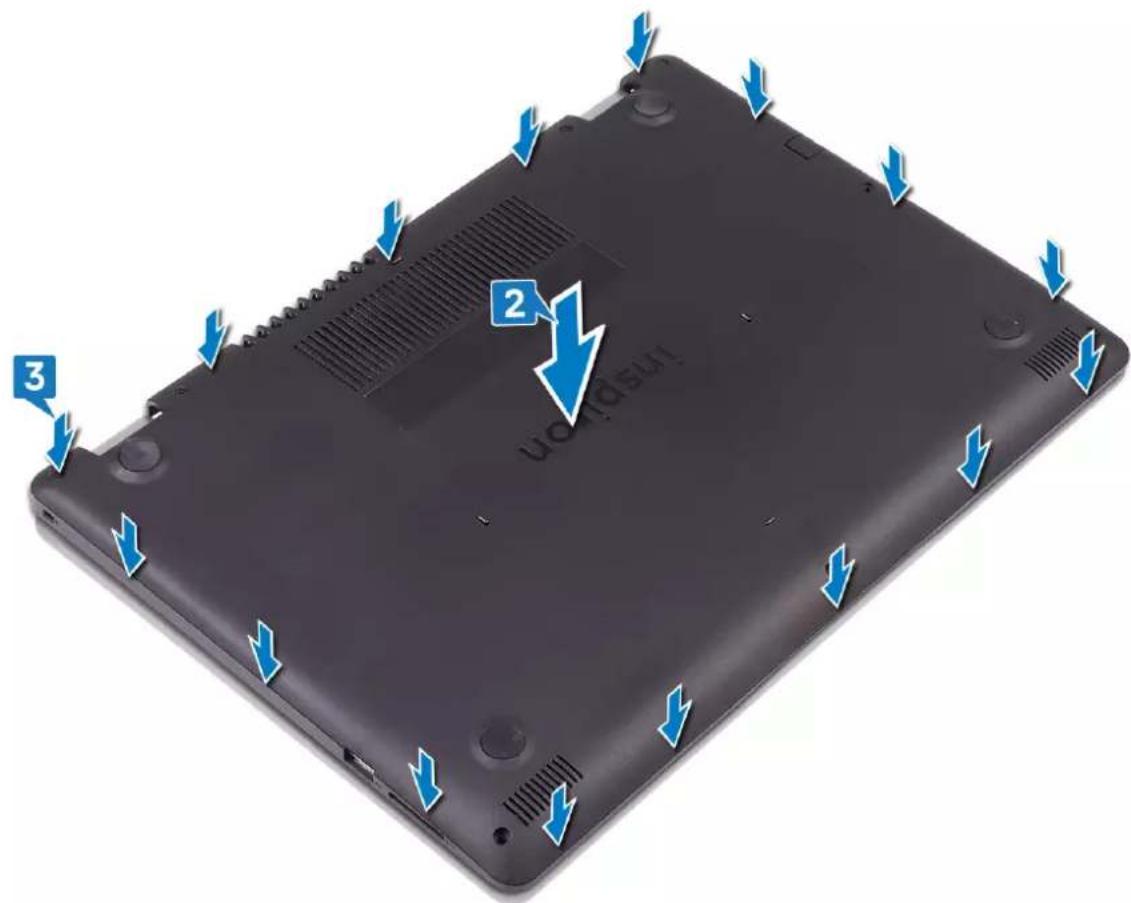
Laptop with battery pack and inset showing a disassembled hard drive component (no text or symbols visible)- Place the base cover on the palm-rest and keyboard assembly.
- Snap the base cover into place.
text_image
UoRdusu 2 3- Replace the six screws (M2.5x4) that secure the base cover to the palm-rest and keyboard assembly.
- Tighten the three captive screws that secure the base cover to the palm-rest and keyboard assembly.
text_image
(UO1010 5 4Removing the battery

NOTE: Before working inside your computer, read the safety information that shipped with your computer and follow the steps in Before working inside your computer. After working inside your computer, follow the instructions in After working inside your computer. For more safety best practices, see the Regulatory Compliance home page at www.dell.com/regulatory_compliance.
Lithium-ion battery precautions

CAUTION:
• Exercise caution when handling Lithium-ion batteries.
- Discharge the battery as much as possible before removing it from the system. This can be done by disconnecting the AC adapter from the system to allow the battery to drain.
- Do not crush, drop, mutilate, or penetrate the battery with foreign objects.
- Do not expose the battery to high temperatures, or disassemble battery packs and cells.
- Do not apply pressure to the surface of the battery.
- Do not bend the battery.
- Do not use tools of any kind to pry on or against the battery.
- Ensure any screws during the servicing of this product are not lost or misplaced, to prevent accidental puncture or damage to the battery and other system components.
- If a battery gets stuck in a device as a result of swelling, do not try to free it as puncturing, bending, or crushing a Lithium-ion battery can be dangerous. In such an instance, contact for assistance and further instructions.
- If the battery gets stuck inside your computer as a result of swelling, do not try to release it as puncturing, bending, or crushing a lithium-ion battery can be dangerous. In such an instance, contact Dell technical support for assistance. See www.dell.com/contactdell.
• Always purchase genuine batteries from www.dell.com or authorized Dell partners and resellers.
Prerequisites
Remove the base cover.
Procedure
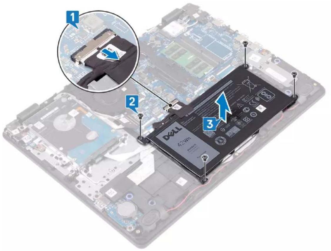
- Disconnect the battery cable from the system board.
- Remove the four screws (M2x3) that secure the battery to the palm-rest and keyboard assembly.
- Lift the battery off the palm-rest and keyboard assembly.
text_image
1 2 3 DZLL 42VWh DZLL 200MHzReplacing the battery

NOTE: Before working inside your computer, read the safety information that shipped with your computer and follow the steps in Before working inside your computer. After working inside your computer, follow the instructions in After working inside your computer. For more safety best practices, see the Regulatory Compliance home page at www.dell.com/regulatory_compliance.
Procedure
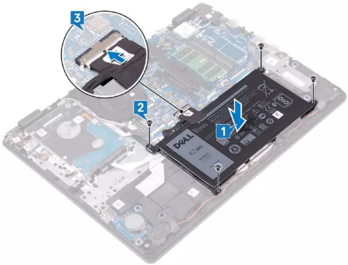
- Align the screw holes on the battery with the screw holes on the palm-rest and keyboard assembly.
- Replace the four screws (M2x3) that secure the battery to the palm-rest and keyboard assembly.
- Connect the battery cable to the system board.
text_image
1 2 3 DZLL 42N8Post-requisites
Replace the base cover.
Removing the memory modules

NOTE: Before working inside your computer, read the safety information that shipped with your computer and follow the steps in Before working inside your computer. After working inside your computer, follow the instructions in After working inside your computer. For more safety best practices, see the Regulatory Compliance home page at www.dell.com/regulatory_compliance.
Prerequisites
Remove the base cover.
Procedure
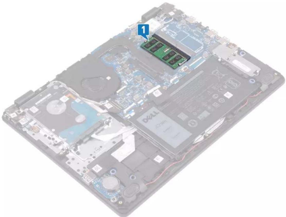
- Locate the memory modules on your computer.
natural_image
Interior view of a computer motherboard showing internal components like CPU, RAM slots, and memory chips (no readable text or symbols)- Use your fingertips to carefully spread apart the securing-clips on each end of the memory-module slot until the memory module pops up.
- Remove the memory module from the memory-module slot.
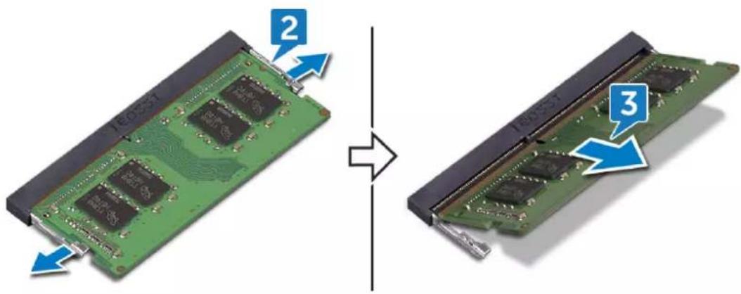
text_image
2 160551 3Replacing the memory modules

NOTE: Before working inside your computer, read the safety information that shipped with your computer and follow the steps in Before working inside your computer. After working inside your computer, follow the instructions in After working inside your computer. For more safety best practices, see the Regulatory Compliance home page at www.dell.com/regulatory_compliance.
Procedure
- Align the notch on the memory module with the tab on the memory-module slot.
- Slide the memory module firmly into the slot at an angle.
- Press the memory module down until it clicks into place.

NOTE: If you do not hear the click, remove the memory module and reinstall it.
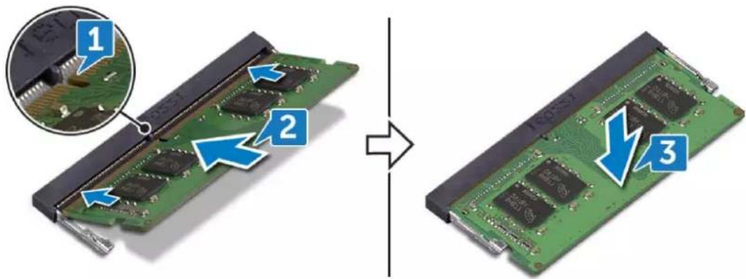
text_image
Diagram showing the process of a microprocessor board with labeled components and directional arrows indicating assembly or repair.Post-requisites
Replace the base cover.
Removing the wireless card

NOTE: Before working inside your computer, read the safety information that shipped with your computer and follow the steps in Before working inside your computer. After working inside your computer, follow the instructions in After working inside your computer. For more safety best practices, see the Regulatory Compliance home page at www.dell.com/regulatory_compliance.
Prerequisites
Remove the base cover.
Procedure
- Locate the wireless card on your computer.
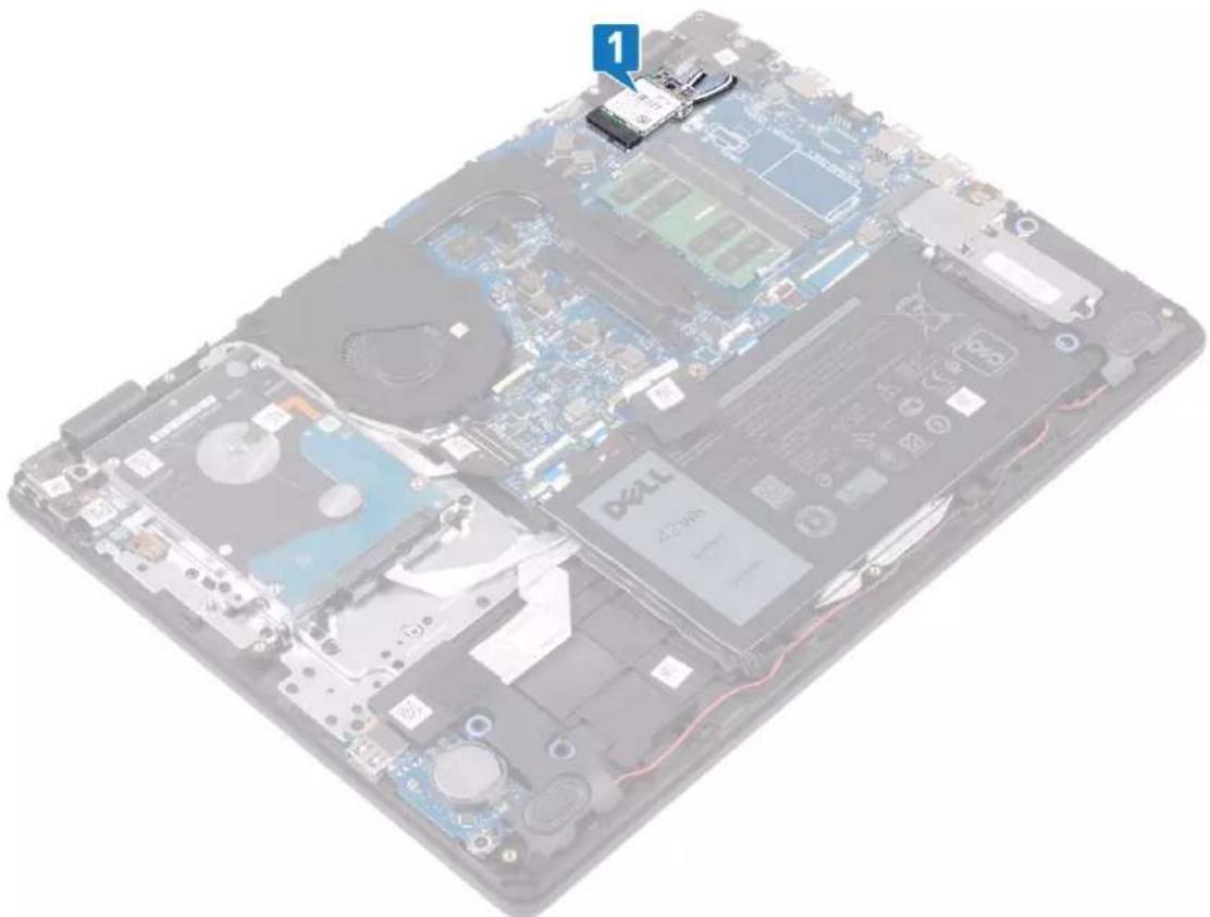
natural_image
Interior view of a laptop motherboard showing CPU socket, drive bays, and memory chips (no text or symbols visible)- Remove the screw (M2x3) that secures the wireless-card bracket to the system board.
- Slide and remove the wireless-card bracket from the wireless card.
- Disconnect the antenna cables from the wireless card.
- Slide and remove the wireless card from the wireless-card slot.
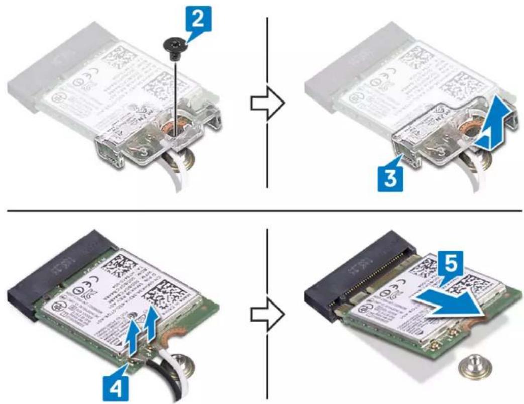
flowchart
graph TD
    A["Device 2"] --> B["Internal Component"]
    B --> C["Component 3"]
    C --> D["Internal Component"]
    D --> E["Component 4"]
    E --> F["Internal Component"]
    F --> G["Component 5"]
Replacing the wireless card

NOTE: Before working inside your computer, read the safety information that shipped with your computer and follow the steps in Before working inside your computer. After working inside your computer, follow the instructions in After working inside your computer. For more safety best practices, see the Regulatory Compliance home page at www.dell.com/regulatory_compliance.
Procedure

CAUTION: To avoid damage to the wireless card, do not place any cables under it.
- Connect the antenna cables to the wireless card.
The following table provides the antenna-cable color scheme for the wireless card that is supported by your computer.
Table 2. Antenna-cable color scheme
| Connectors on the wireless card Antenna-cable color | |
| Main (white triangle) White | |
| Auxiliary (black triangle) Black |
- Slide and replace the wireless-card bracket on the wireless-card.
- Align the notch on the wireless card with the tab on the wireless-card slot and insert the wireless card at an angle into the wireless-card slot.
- Replace the screw (M2x3) that secures the wireless-card bracket to the wireless card and the palm rest and keyboard assembly.
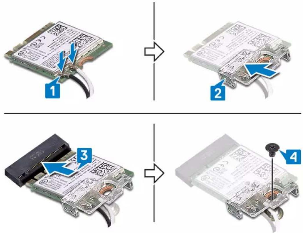
flowchart
graph TD
    A["1: Card slot with cable"] --> B["2: Cable package with cable"]
    B --> C["3: Cable pad with cable"]
    C --> D["4: Battery pack assembly with screw"]
Post-requisites
Replace the base cover.
Removing the coin-cell battery

NOTE: Before working inside your computer, read the safety information that shipped with your computer and follow the steps in Before working inside your computer. After working inside your computer, follow the instructions in After working inside your computer. For more safety best practices, see the Regulatory Compliance home page at www.dell.com/regulatory_compliance.

CAUTION: Removing the coin-cell battery resets the BIOS setup program's settings to default. It is recommended that you note the BIOS setup program's settings before removing the coin-cell battery.
Prerequisites
Remove the base cover.
Procedure
Using a plastic scribe, gently pry the coin-cell battery out of the battery socket on the I/O board.
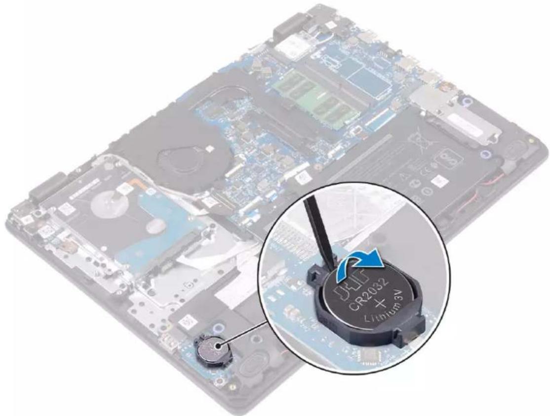
natural_image
Laptop with visible circuit board and a close-up of a ULT CR2032 + 3V battery cover (no text or symbols on the main subject)Replacing the coin-cell battery

NOTE: Before working inside your computer, read the safety information that shipped with your computer and follow the steps in Before working inside your computer. After working inside your computer, follow the instructions in After working inside your computer. For more safety best practices, see the Regulatory Compliance home page at www.dell.com/regulatory_compliance.
Procedure
With the positive-side facing up, snap the coin-cell battery into the battery socket on the I/O board.
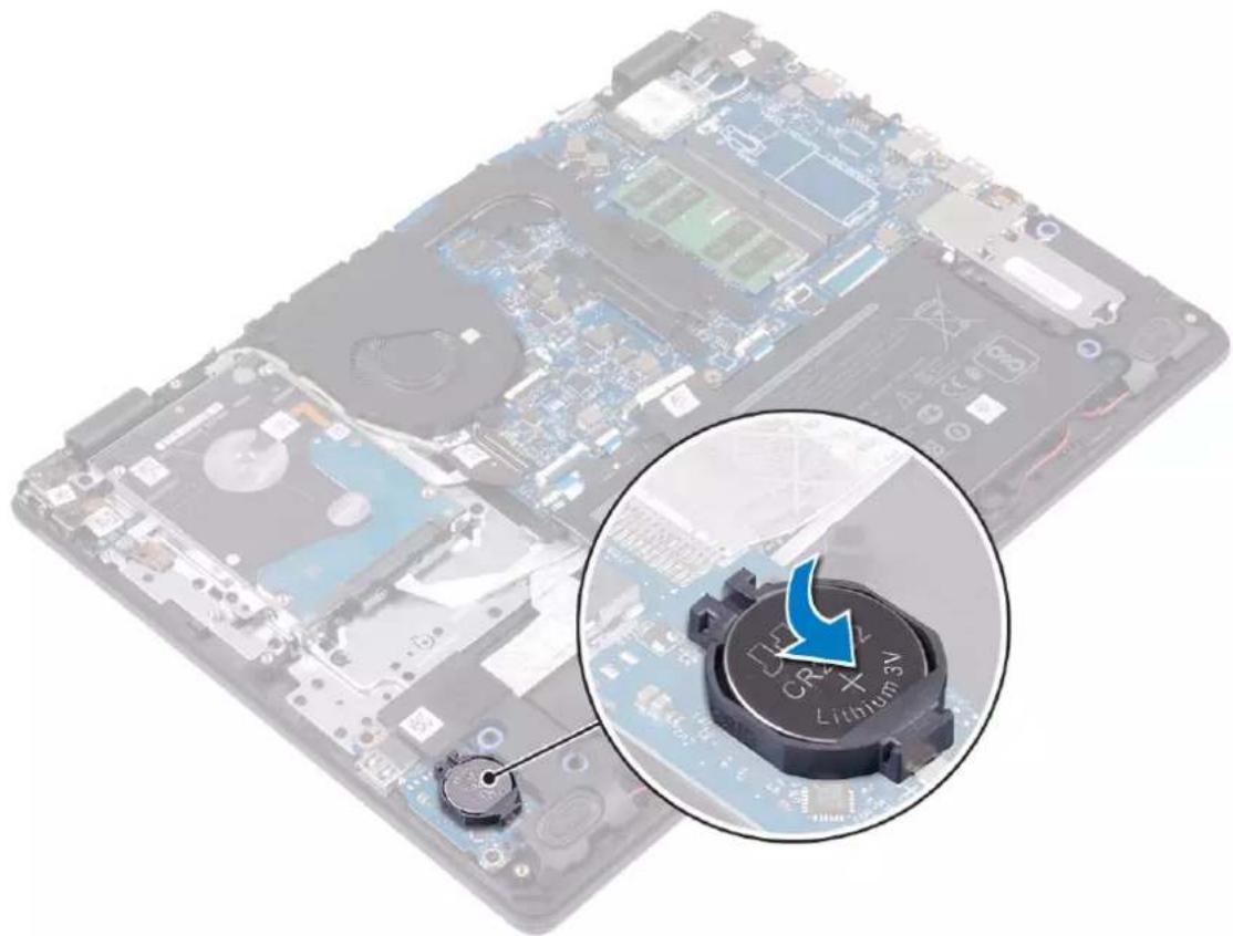
natural_image
Laptop motherboard with a highlighted lithium battery component (no text or symbols on the main image)Post-requisites
Replace the base cover.
Removing the fan

NOTE: Before working inside your computer, read the safety information that shipped with your computer and follow the steps in Before working inside your computer. After working inside your computer, follow the instructions in After working inside your computer. For more safety best practices, see the Regulatory Compliance home page at www.dell.com/regulatory_compliance.
Prerequisites
Remove the base cover.
Procedure
- Disconnect the fan cable from the system board.
- Remove the two screws (M2.5x5) that secure the fan to the palm rest and keyboard board assembly.
- Remove the display cable from the routing guides on the fan.
- Lift the fan off the palm rest and keyboard board assembly.
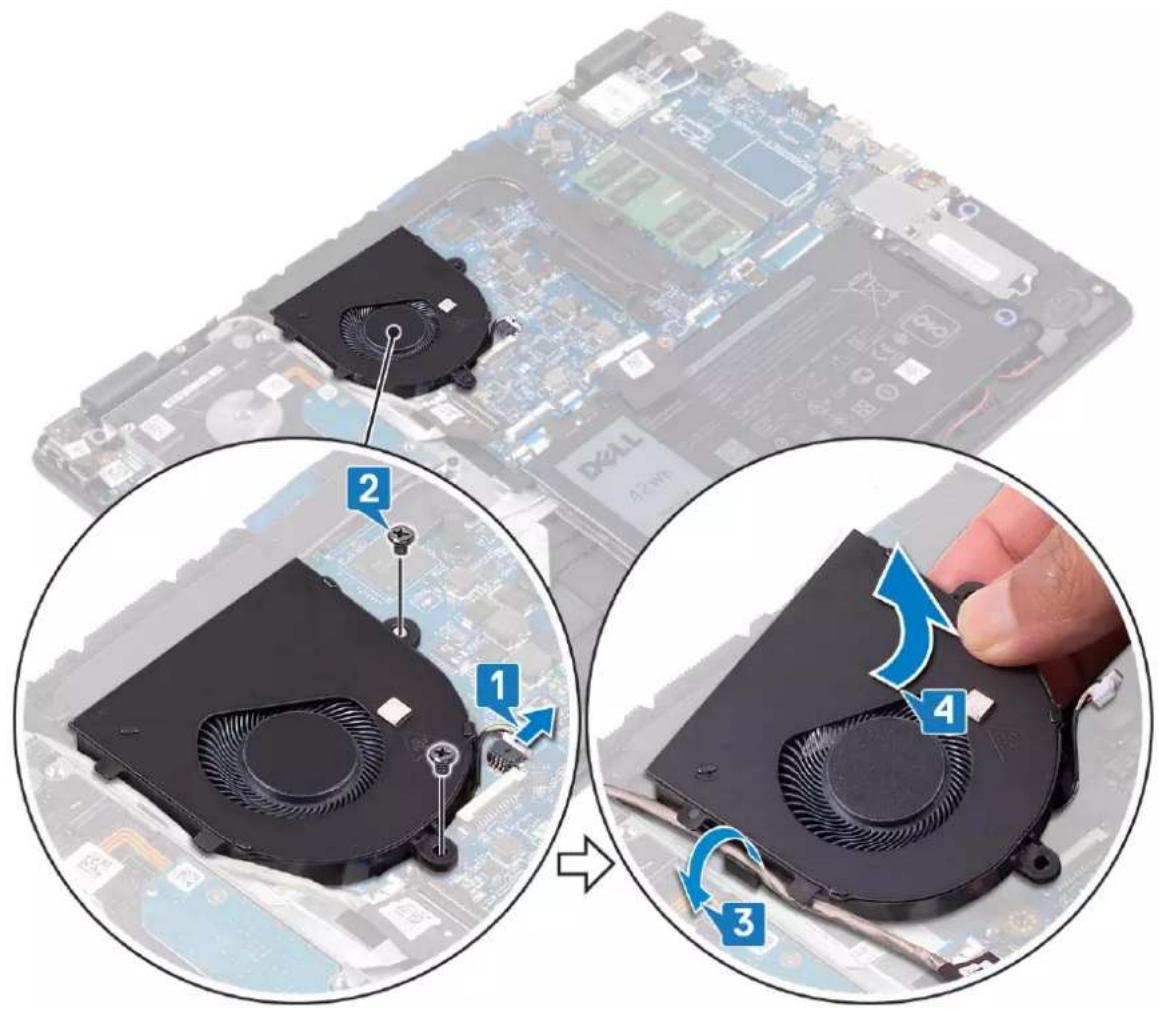
text_image
Diagram showing a computer motherboard with labeled components and a hand adjusting the fan blade, illustrating steps 1 to 4.Replacing the fan

NOTE: Before working inside your computer, read the safety information that shipped with your computer and follow the steps in Before working inside your computer. After working inside your computer, follow the instructions in After working inside your computer. For more safety best practices, see the Regulatory Compliance home page at www.dell.com/regulatory_compliance.
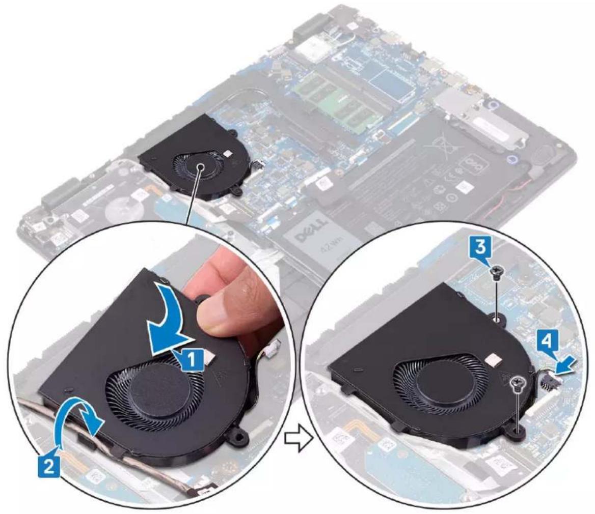
Procedure
- Align the screw holes on the fan with the screw holes on to the palm rest and keyboard board assembly.
- Route the display cable through the routing guides on the fan.
- Replace the three screws (M2.5x5) that secure the fan to the palm rest and keyboard board assembly.
- Connect the fan cable to the system board.
text_image
Diagram showing a computer motherboard with labeled components, including fan blades and heat transfer stepsPost-requisites
Replace the base cover.
Removing the heat sink
NOTE: Before working inside your computer, read the safety information that shipped with your computer and follow the steps in Before working inside your computer. After working inside your computer, follow the instructions in After working inside your computer. For more safety best practices, see the Regulatory Compliance home page at www.dell.com/regulatory_compliance.
NOTE: The heat sink may become hot during normal operation. Allow sufficient time for the heat sink to cool before you touch it.
CAUTION: For maximum cooling of the processor, do not touch the heat transfer areas on the heat sink. The oils in your skin can reduce the heat transfer capability of the thermal grease.
Prerequisites
Remove the base cover.
Procedure
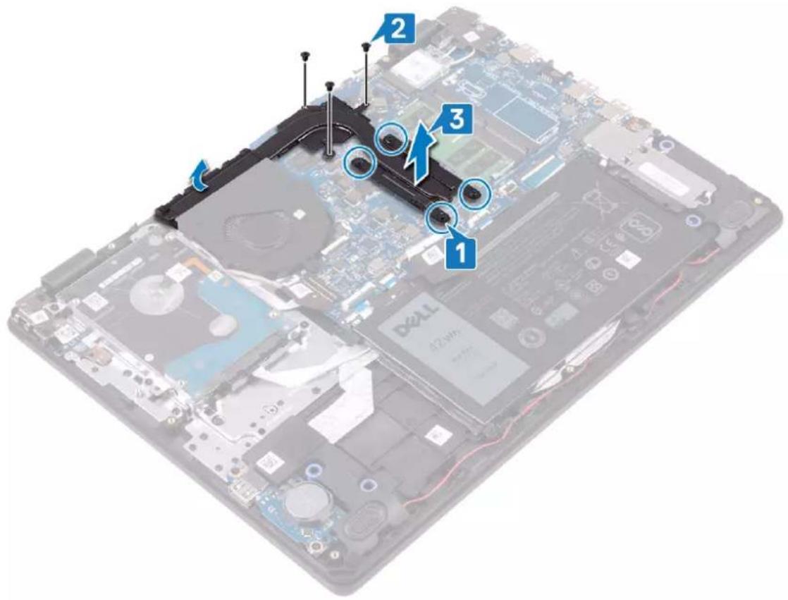
- In reversed order (as indicated on the heat sink), loosen the four captive screws that secure the heat sink to the system board.
- Remove the three (M2x3) screws that secure the heat sink to the system board.
NOTE: The number of screws may vary depending on the configuration ordered.
- Lift the heat sink off the system board.
text_image
Labeled diagram of a laptop motherboard showing numbered components and battery modulesReplacing the heat sink
NOTE: Before working inside your computer, read the safety information that shipped with your computer and follow the steps in Before working inside your computer. After working inside your computer, follow the instructions in After working inside your computer. For more safety best practices, see the Regulatory Compliance home page at www.dell.com/regulatory_compliance.
CAUTION: Incorrect alignment of the heat sink can damage the system board and processor.
NOTE: If either the system board or the heat sink is replaced, use the thermal pad provided in the kit to ensure that thermal conductivity is achieved.
Procedure
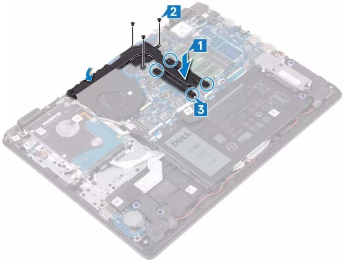
- Place the heat sink on the system board and align the screw holes on the heat sink with the screw holes on the system board.
- Replace the three (M2x3) screws that secure the heat sink to the system board.
- In sequential order (as indicated on the heat sink), tighten the four captive screws that secure the heat sink to the system board.
text_image
Labeled diagram of a Dell computer motherboard showing components numbered 1, 2, and 3 with annotations for device parts.Post-requisites
Replace the base cover.
Removing the solid-state drive/Intel Optane memory module
You need to disable the Intel Optane memory before removing Intel Optane memory module from your computer. For more information about disabling the Intel Optane memory, see Disabling Intel Optane memory.

NOTE: Before working inside your computer, read the safety information that shipped with your computer and follow the steps in Before working inside your computer. After working inside your computer, follow the instructions in After working inside your computer. For more safety best practices, see the Regulatory Compliance home page at www.dell.com/regulatory_compliance.
Prerequisites
Remove the base cover.
Procedure
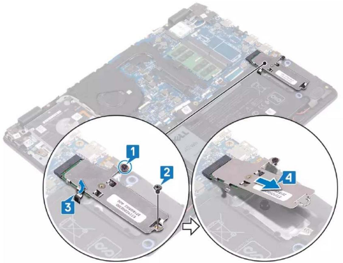
- Loosen the captive screw that secures the solid-state drive shield/Intel Optane shield and solid-state drive/Intel Optane to the palm rest and keyboard assembly.
- Remove the screw that secures the solid-state drive shield/Intel Optane shield to the palm rest and keyboard assembly.
- Slide and remove the solid-state drive/Intel Optane from the solid-state drive/Intel Optane slot.
- Slide and remove the solid-state drive/Intel Optane from the solid-state drive/Intel Optane slot.
text_image
Diagram showing a computer motherboard with four labeled components and a close-up of the device's internal structure, likely illustrating a hardware or system assembly.- Turn the solid-state drive shield/Intel Optane shield over.
- Remove the screw that secures the solid-state drive/Intel Optane to the solid-state drive shield/Intel Optane shield.
- Lift the solid-state drive/Intel Optane off the solid-state drive shield/Intel Optane shield.
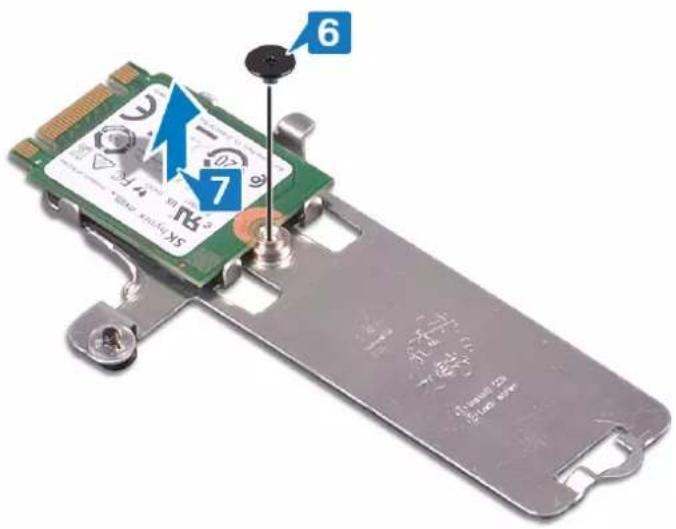
text_image
6 7 1/4 Micro keyboard X5Replacing the solid-state drive/Intel Optane memory module
Enable the Intel Optane memory after you replace the Intel Optane memory module. For more information about enabling the Intel Optane memory, see Enabling Intel Optane memory.

NOTE: Before working inside your computer, read the safety information that shipped with your computer and follow the steps in Before working inside your computer. After working inside your computer, follow the instructions in After working inside your computer. For more safety best practices, see the Regulatory Compliance home page at www.dell.com/regulatory_compliance.

CAUTION: Solid-state drives are fragile. Exercise care when handling the solid-state drive.
Procedure
- Place the solid-state drive/Intel Optane into the slot on the back of the solid-state drive shield/Intel Optane shield.
- Replace the screw that secures the solid-state drive/Intel Optane to the solid-state drive shield/Intel Optane shield.
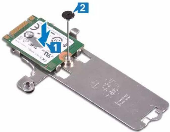
text_image
1 2 S3X 10.5V 10.5V 10.5V- Align the notch on the solid-state drive/Intel Optane with the tab on the solid-state drive/Intel Optane slot.
- Slide the solid-state drive/Intel Optane into the solid-state drive/Intel Optane slot.
- Insert the tab of the solid-state drive/Intel Optane into the slot on the palm-rest and keyboard assembly.
- Tighten the captive screw that secures the solid-state drive shield/Intel Optane shield and solid-state drive/Intel Optane to the palm rest and keyboard assembly.
- Replace the screw that secures the solid-state drive shield/Intel Optane shield to the palm-rest and keyboard assembly.
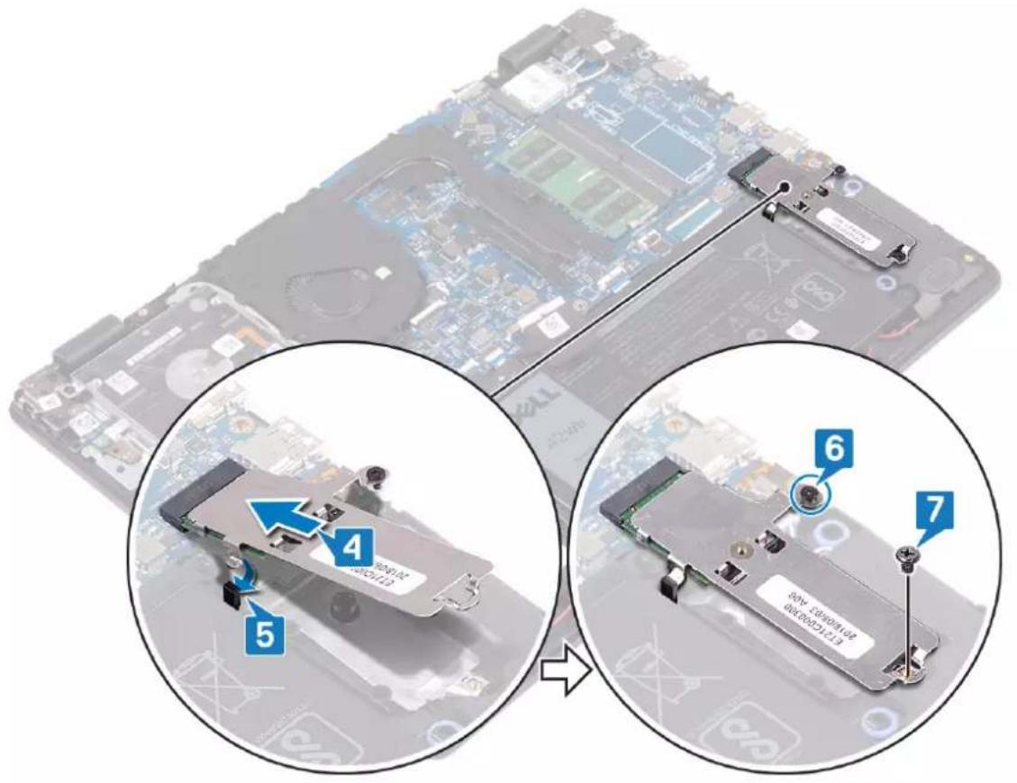
text_image
Diagram showing a computer motherboard with labeled components and a close-up of the device's internal structure, including numbered parts 4, 5, 6, and 7.Post-requisites
Replace the base cover.
Removing the hard drive
If your computer is using a SATA storage device accelerated by Intel Optane memory, disable Intel Optane before removing the SATA storage device. For more information about disabling the Intel Optane, see Disabling Intel Optane.

NOTE: Before working inside your computer, read the safety information that shipped with your computer and follow the steps in Before working inside your computer. After working inside your computer, follow the instructions in After working inside your computer. For more safety best practices, see the Regulatory Compliance home page at www.dell.com/regulatory_compliance.

CAUTION: Hard drives are fragile. Exercise care when handling the hard drive.

CAUTION: To avoid data loss, do not remove the hard drive while the computer is in sleep or on state.
Prerequisites
- Remove the base cover.
- Remove the battery.
Procedure
- Open the latch and disconnect the hard-drive cable from the system board.
- Remove the four screws (M2x3) that secure the hard-drive assembly to the palm rest and keyboard assembly.
- Lift the hard-drive assembly along with its cable off the palm rest and keyboard assembly.
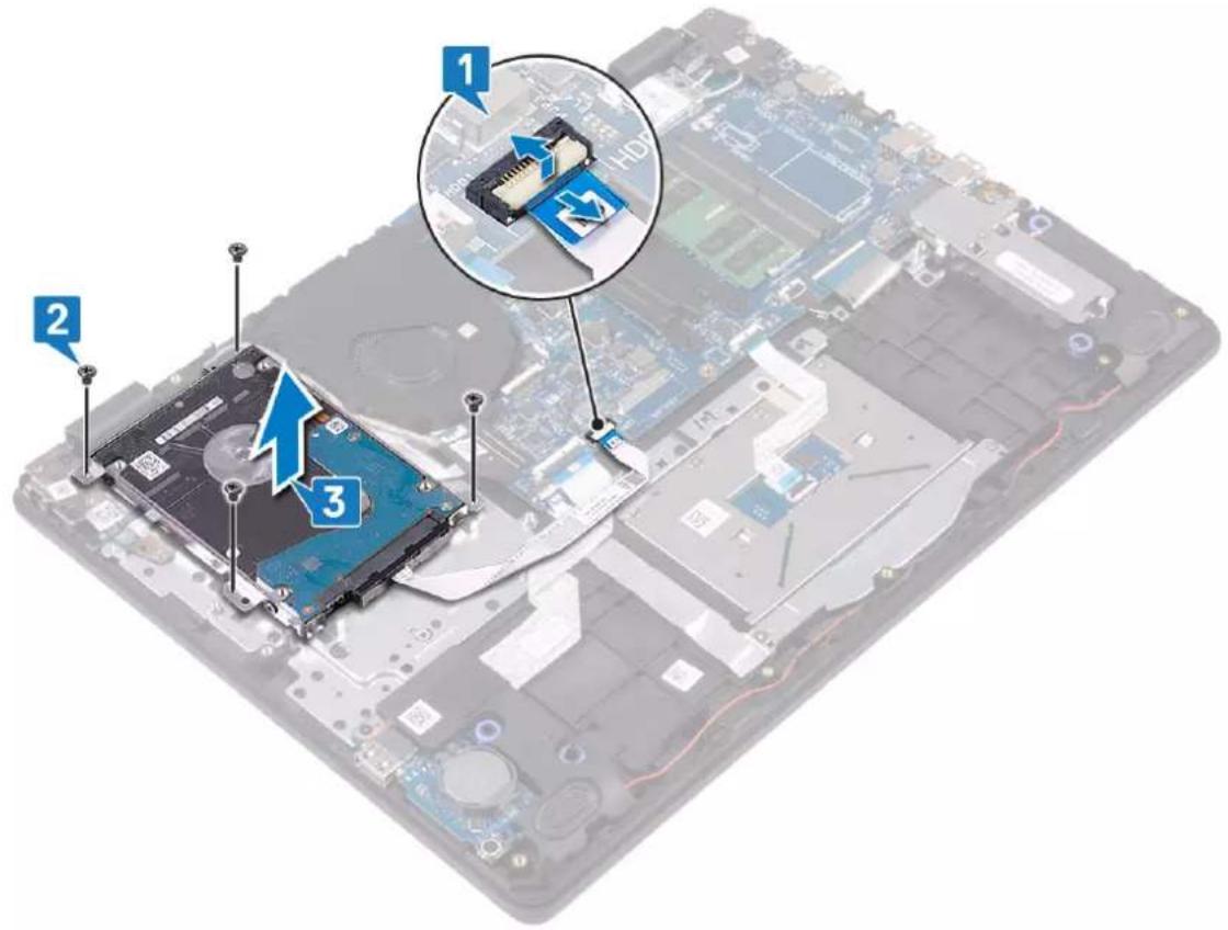
text_image
Labeled diagram of a computer motherboard showing components 1, 2, and 3 with annotations and arrows indicating assembly or installation.42 Removing the hard drive
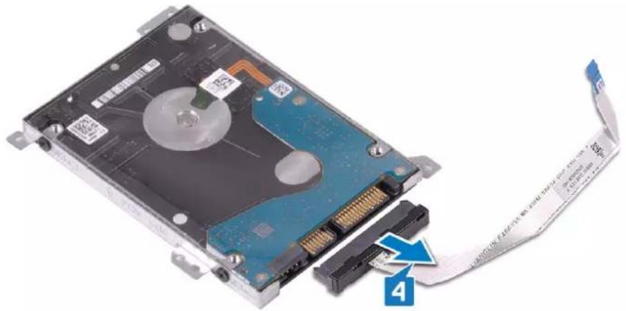
- Disconnect the interposer from the hard-drive assembly.
natural_image
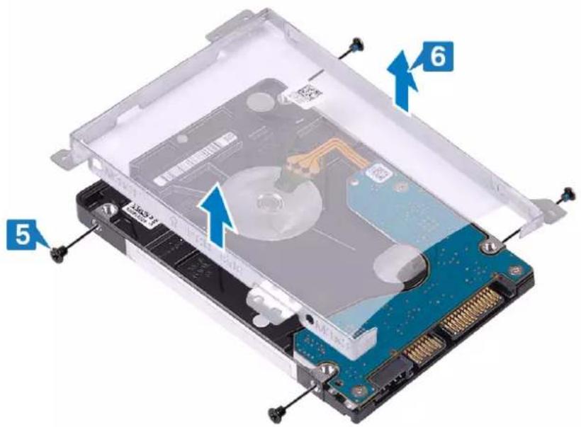
Internal view of a hard disk drive with attached cable and connector (no text or symbols visible)- Remove the four screws (M3x3) that secure the hard-drive bracket to the hard drive.
- Lift the hard-drive bracket off the hard drive.
text_image
Diagram of an open hard disk drive showing internal components and labeled parts (5, 6)Replacing the hard drive
Enable Intel Optane after replacing the SATA storage. For more information about enabling the Intel Optane, see Enabling Intel Optane.

NOTE: Before working inside your computer, read the safety information that shipped with your computer and follow the steps in Before working inside your computer. After working inside your computer, follow the instructions in After working inside your computer. For more safety best practices, see the Regulatory Compliance home page at www.dell.com/regulatory_compliance.

CAUTION: Hard drives are fragile. Exercise care when handling the hard drive.
Procedure
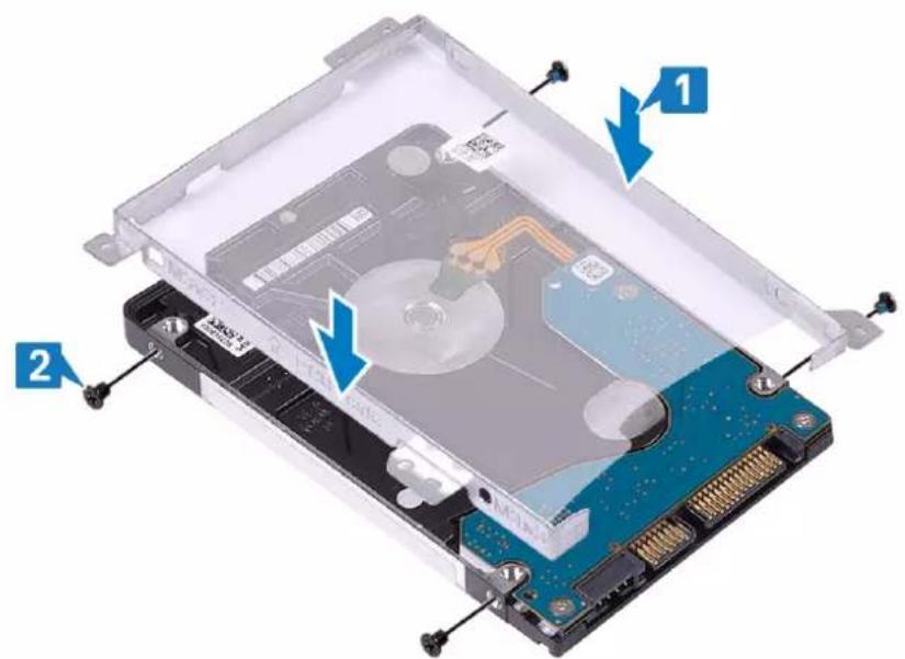
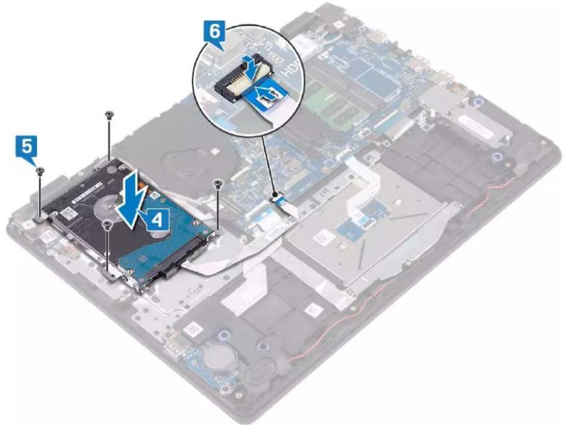
- Align the screw holes on the hard-drive bracket with the screw holes on the hard drive.
- Replace the four screws (M3x3) that secure the hard-drive bracket to the hard drive.
text_image
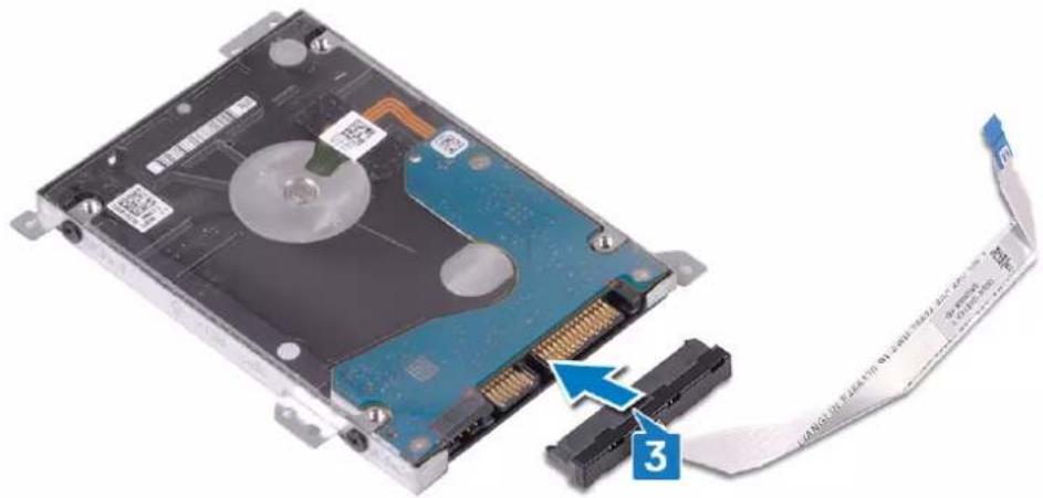
Diagram of an open hard disk drive showing internal components and labeled parts 1 and 2- Connect the interposer to the hard-drive assembly.
natural_image
Close-up of a hard disk drive with attached cable and connector (no visible text or symbols)- Align the screw holes on the hard-drive assembly with the screw holes on the palm rest and keyboard assembly.
- Replace the four screws (M2x3) that secure the hard-drive assembly to the palm rest and keyboard assembly.
- Connect the hard-drive cable to the system board and close the latch to secure the cable.
text_image
5 4 6 13Post-requisites
- Replace the battery.
- Replace the base cover.
Removing the touchpad

NOTE: Before working inside your computer, read the safety information that shipped with your computer and follow the steps in Before working inside your computer. After working inside your computer, follow the instructions in After working inside your computer. For more safety best practices, see the Regulatory Compliance home page at www.dell.com/regulatory_compliance.
Prerequisites
- Remove the base cover.
- Remove the battery.
Procedure
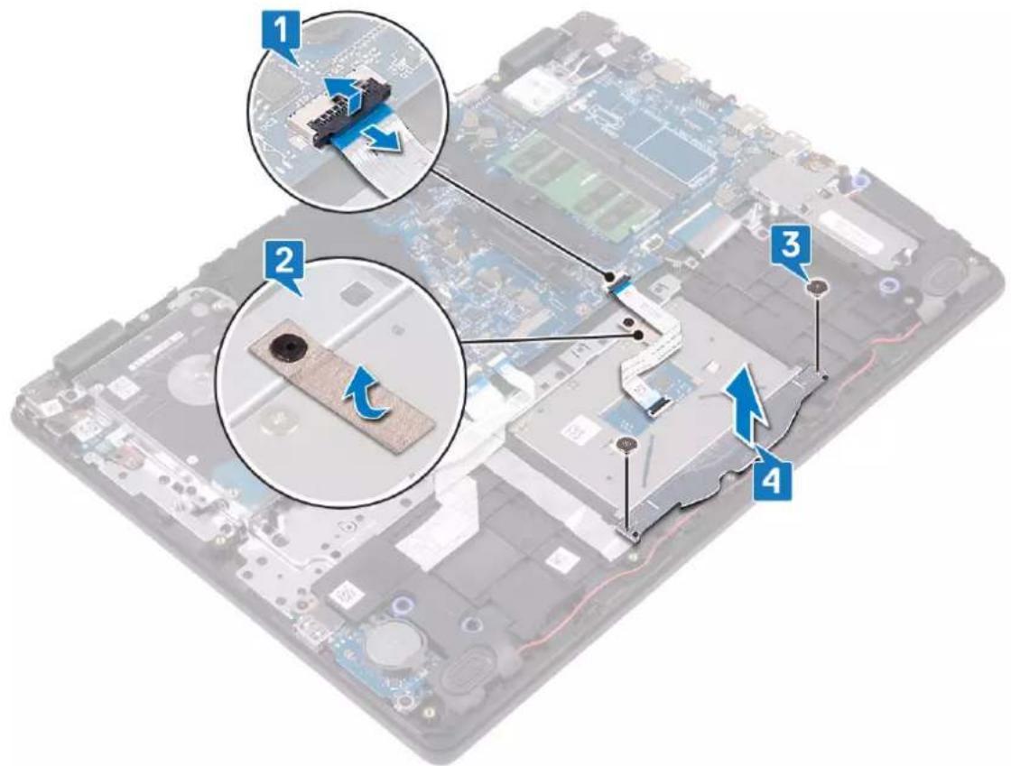
- Open the latch and disconnect the touchpad cable from the system board.
- Peel the tape that secures the touchpad to the palm-rest and keyboard assembly.
- Remove the two screws (M2x2) that secure the touchpad bracket to the palm rest and keyboard assembly.
- Lift the touchpad bracket off the palm rest and keyboard assembly.
text_image
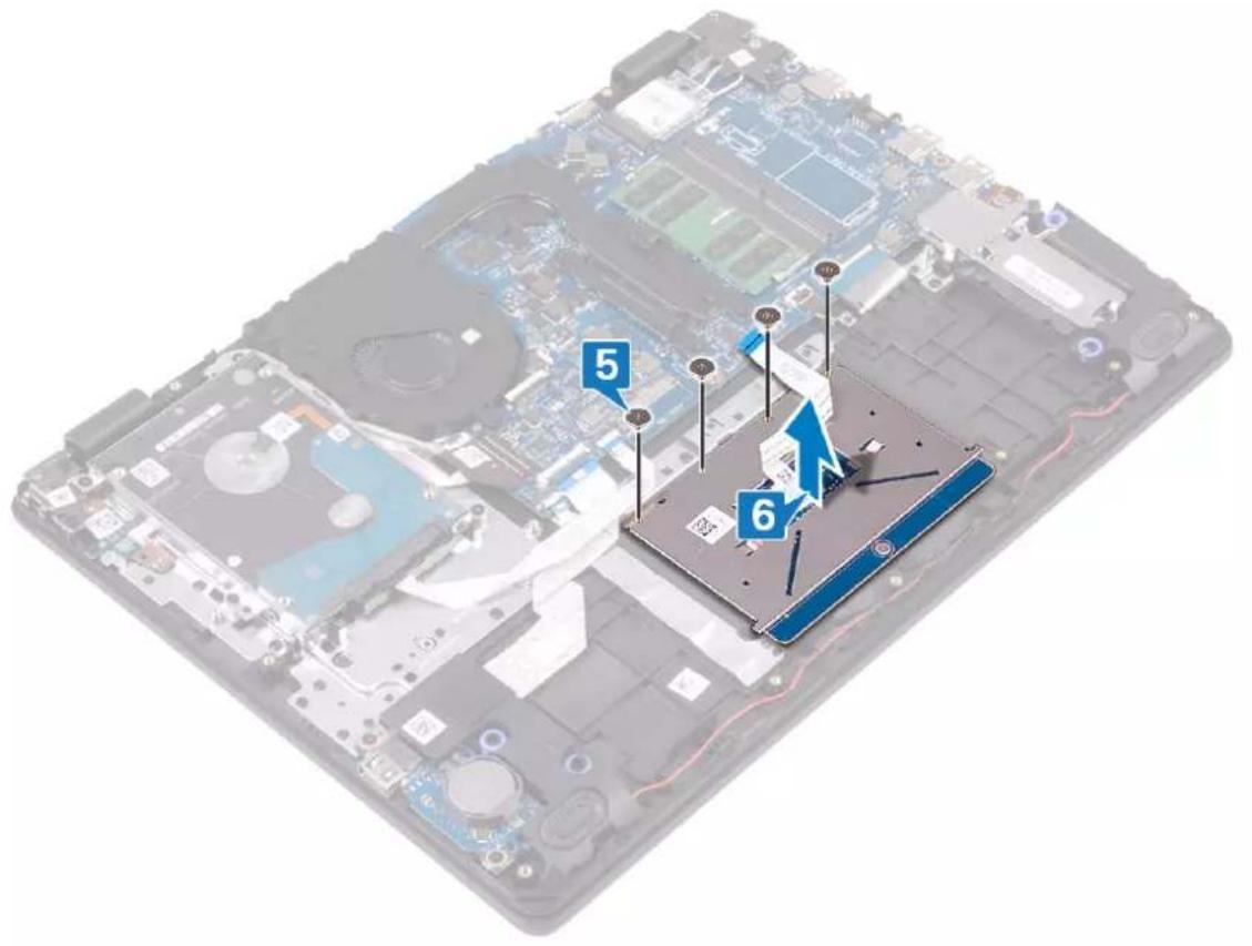
Labeled diagram of a computer motherboard showing component connections and parts numbered 1 to 4- Remove the four screws (M2x2) that secure the touchpad to the palm rest and keyboard assembly.
- Lift the touchpad off the palm rest and keyboard assembly.
text_image
5 6Replacing the touchpad
NOTE: Before working inside your computer, read the safety information that shipped with your computer and follow the steps in Before working inside your computer. After working inside your computer, follow the instructions in After working inside your computer. For more safety best practices, see the Regulatory Compliance home page at www.dell.com/regulatory_compliance.
Procedure
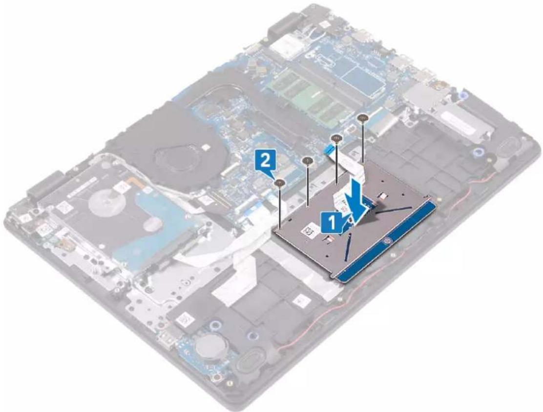
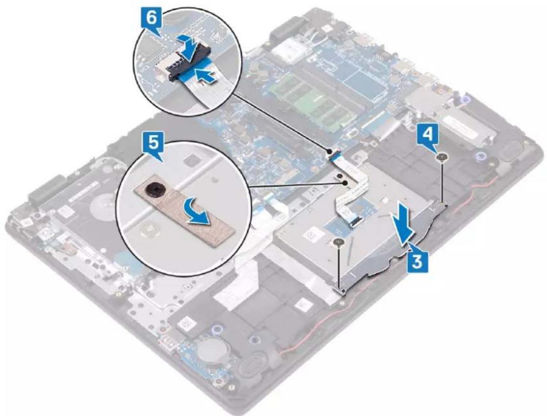
NOTE: Ensure that the touchpad is aligned with the guides available on the palm-rest and keyboard assembly, and the gap on either sides of the touchpad is equal.
- Place the touchpad into the slot on the palm rest and keyboard assembly.
- Replace the four screws (M2x2) that secure the touchpad to the palm rest and keyboard assembly.
text_image
Labeled diagram of a computer hard drive showing components numbered 1, 2, and 3 on a circuit board background- Place the touchpad bracket into the slot on the palm rest and keyboard assembly.
- Replace the two screws (M2x2) that secure the touchpad bracket to the palm rest and keyboard assembly.
- Adhere the tape that secures the touchpad to the palm rest and keyboard assembly.
- Slide the touchpad cable into its connector on the system board and close the latch to secure the cable.
text_image
Labeled diagram of a computer motherboard showing component parts and directional arrows, with numbered annotations.Post-requisites
- Replace the battery.
- Replace the base cover.
Removing the speakers

NOTE: Before working inside your computer, read the safety information that shipped with your computer and follow the steps in Before working inside your computer. After working inside your computer, follow the instructions in After working inside your computer. For more safety best practices, see the Regulatory Compliance home page at www.dell.com/regulatory_compliance.
Prerequisites
- Remove the base cover.
- Remove the solid-state drive/Intel Optane.
Procedure
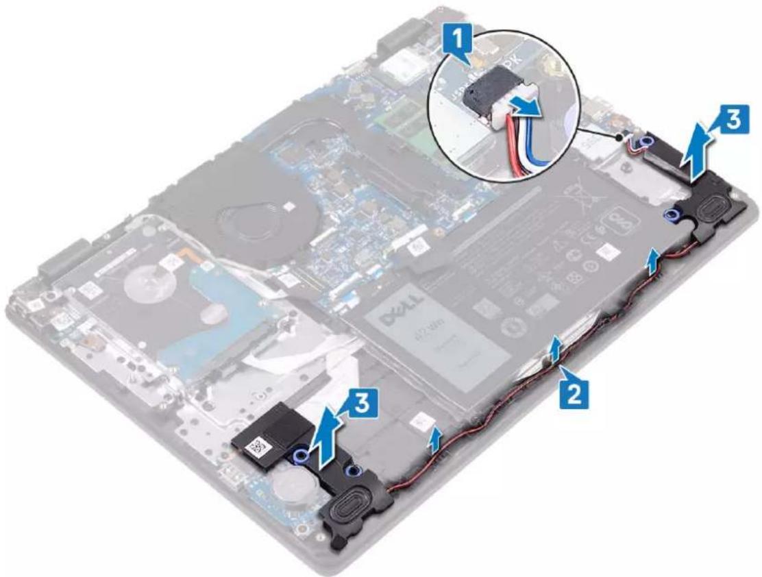
- Disconnect the speaker cable from the system board.
- Note the speaker cable routing and remove it from the routing guides on palm rest and keyboard assembly.
- Lift the speakers, along with the cable, off the palm rest and keyboard assembly.
text_image
Labeled diagram of a laptop showing internal components and cable connections, with numbered annotations pointing to specific parts.Replacing the speakers
NOTE: Before working inside your computer, read the safety information that shipped with your computer and follow the steps in Before working inside your computer. After working inside your computer, follow the instructions in After working inside your computer. For more safety best practices, see the Regulatory Compliance home page at www.dell.com/regulatory_compliance.
Procedure
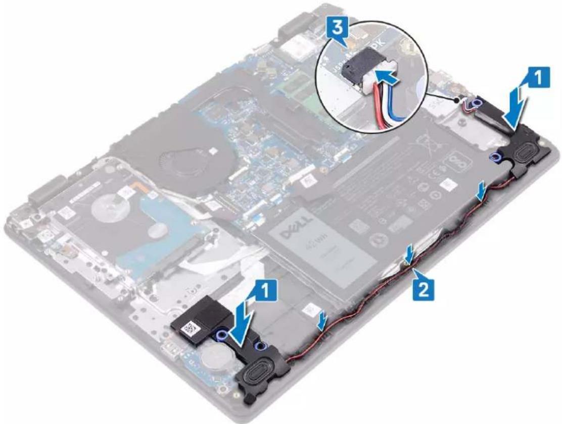
NOTE: If the rubber grommets are pushed out when removing the speakers, push them back in before replacing the speakers.
- Using the alignment posts and rubber grommets, place the speakers in the slots on the palm rest and keyboard assembly.
- Route the speaker cable through the routing guides on the palm rest and keyboard assembly.
- Connect the speaker cable to the system board.
text_image
Labeled diagram of a laptop motherboard showing three numbered components with cable and wiring connectionsPost-requisites
- Replace the solid-state drive/Intel Optane.
- Replace the base cover.
Removing the I/O board

NOTE: Before working inside your computer, read the safety information that shipped with your computer and follow the steps in Before working inside your computer. After working inside your computer, follow the instructions in After working inside your computer. For more safety best practices, see the Regulatory Compliance home page at www.dell.com/regulatory_compliance.
Prerequisites

CAUTION: Removing the coin-cell battery resets the BIOS setup program's settings to default. Before removing the I/O board along with the coin-cell battery, it is recommended to note the BIOS setup program's settings.
- Remove the base cover.
- Remove the solid-state drive/Intel Optane.
- Remove the speakers.
Procedure
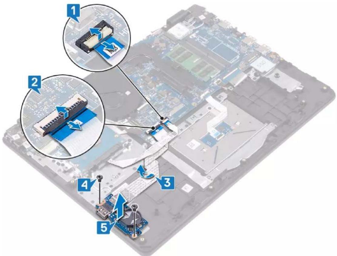
- Open the latch and disconnect the hard-drive cable from the system board.
- Open the latch and disconnect the I/O-board cable from the system board.
- Peel the I/O-board cable from the palm rest and keyboard assembly.
- Remove the two screws (M2x4) that secure the I/O board to the palm rest and keyboard assembly.
- Lift the I/O board, along with the cable, off the palm rest and keyboard assembly.
text_image
Diagram showing five labeled components of a computer motherboard with annotations in Chinese, including a connector pin and circuit board.Replacing the I/O board

NOTE: Before working inside your computer, read the safety information that shipped with your computer and follow the steps in Before working inside your computer. After working inside your computer, follow the instructions in After working inside your computer. For more safety best practices, see the Regulatory Compliance home page at www.dell.com/regulatory_compliance.
Procedure
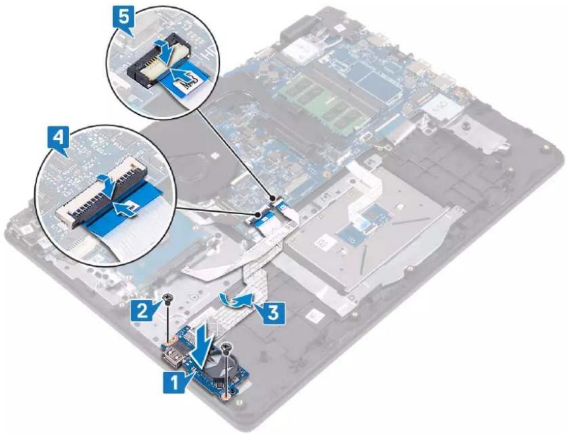
- Using the alignment posts, place the I/O board on the palm rest and keyboard assembly.
- Replace the two screws (M2x4) that secure the I/O board to the palm rest and keyboard assembly.
- Adhere the I/O-board cable to the palm rest and keyboard assembly.
- Connect the hard-drive cable to the system board and close the latch to secure the cable.
- Connect the I/O-board cable to the system board and close the latch to secure the cable.
text_image
Labeled diagram of a computer motherboard showing numbered components and assembly stepsPost-requisites
- Replace the speakers.
- Replace the solid-state drive/Intel Optane.
- Replace the base cover.
Removing the display assembly

NOTE: Before working inside your computer, read the safety information that shipped with your computer and follow the steps in Before working inside your computer. After working inside your computer, follow the instructions in After working inside your computer. For more safety best practices, see the Regulatory Compliance home page at www.dell.com/regulatory_compliance.
Prerequisites
- Remove the base cover.
- Remove the wireless card.
- Remove the fan.
Procedure
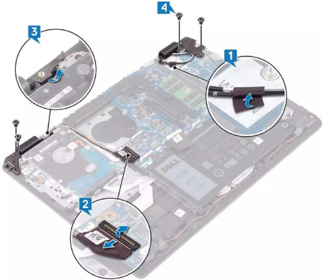
- Note the routing of the antenna cables and peel off the cables from the system board.
- Open the latch and disconnect the display cable from the system board.
- Remove the display cable from the routing guides on the palm-rest and keyboard assembly.
- Remove the four screws (M2.5x4) that secure the left and right hinges to the system board and I/O board.
text_image
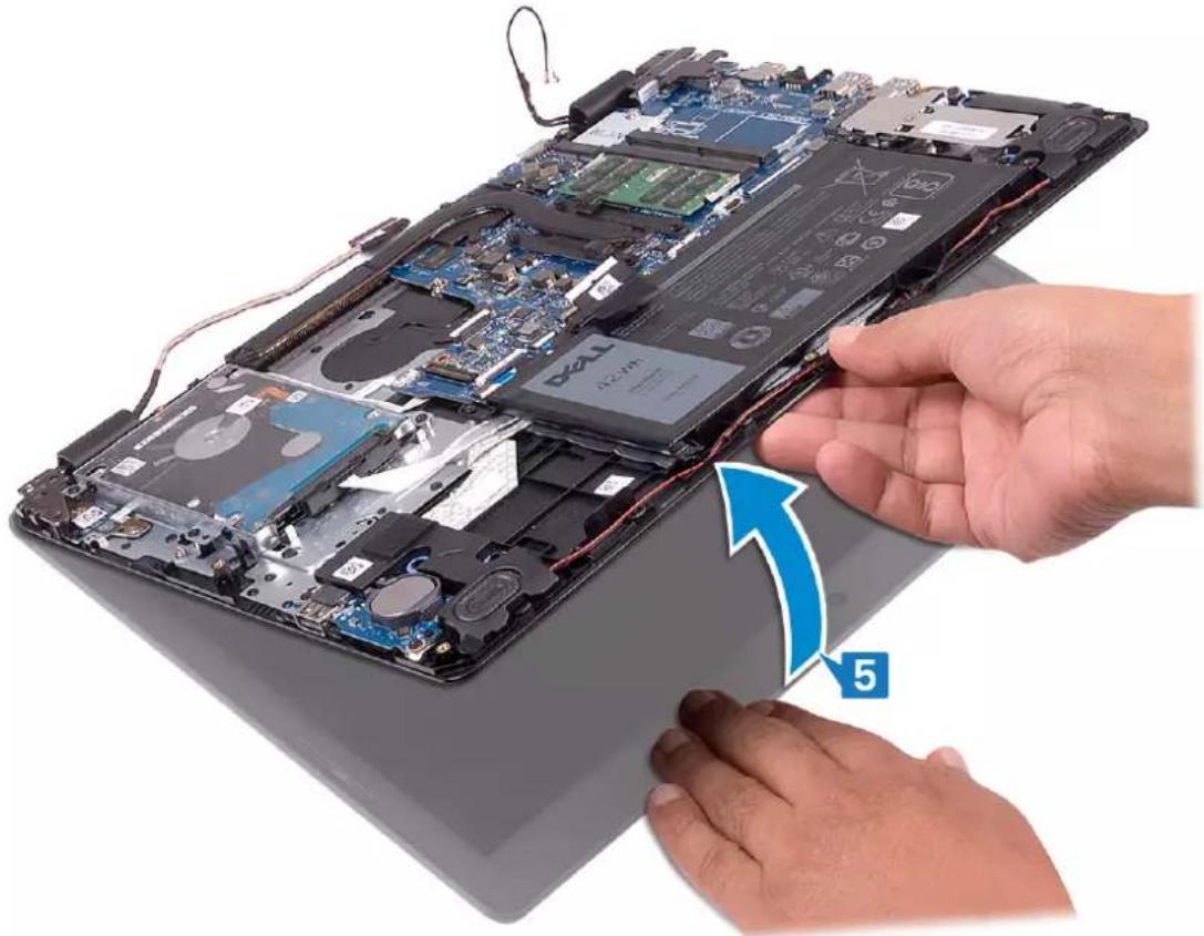
Laptop hardware components with numbered annotations showing assembly steps and component placement- Lift the palm-rest and keyboard assembly at an angle.
natural_image
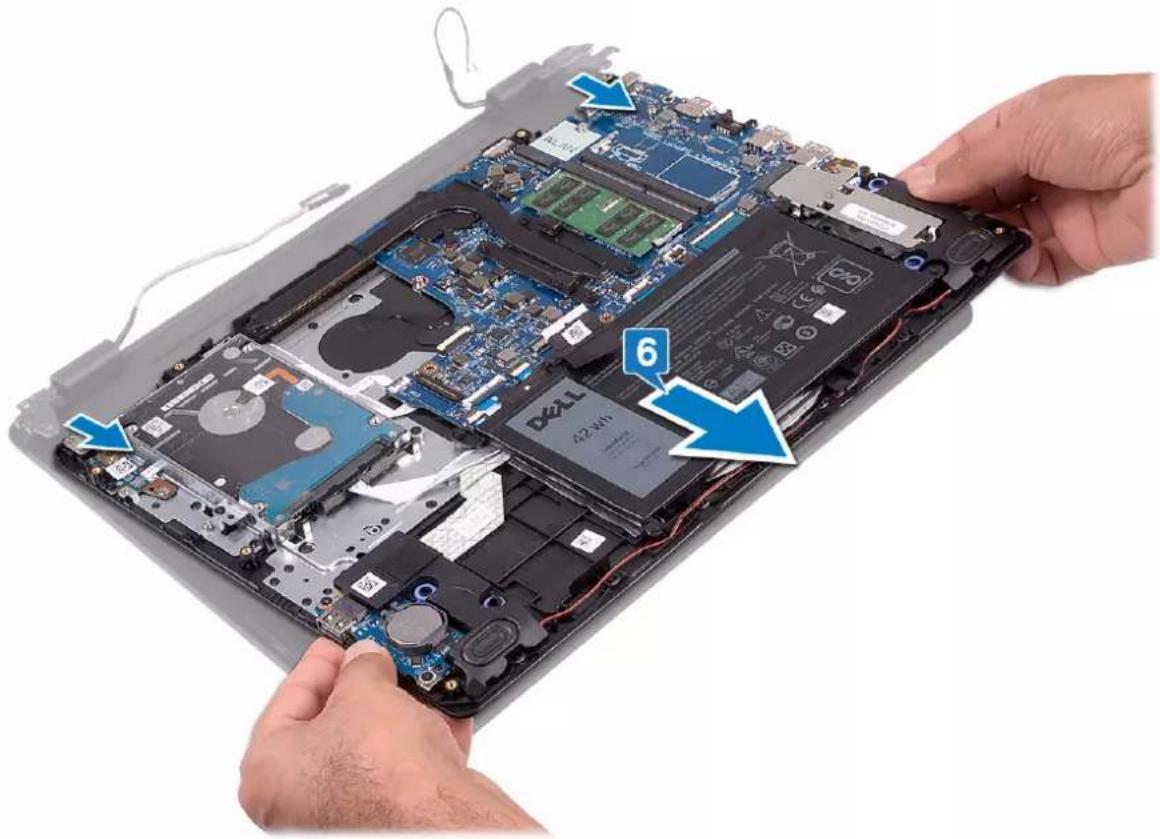
Close-up of hands installing or adjusting a laptop motherboard with a blue arrow pointing to component 5 (no text or symbols on the main subject)- Slide and remove the palm-rest and keyboard assembly off the display assembly.
natural_image
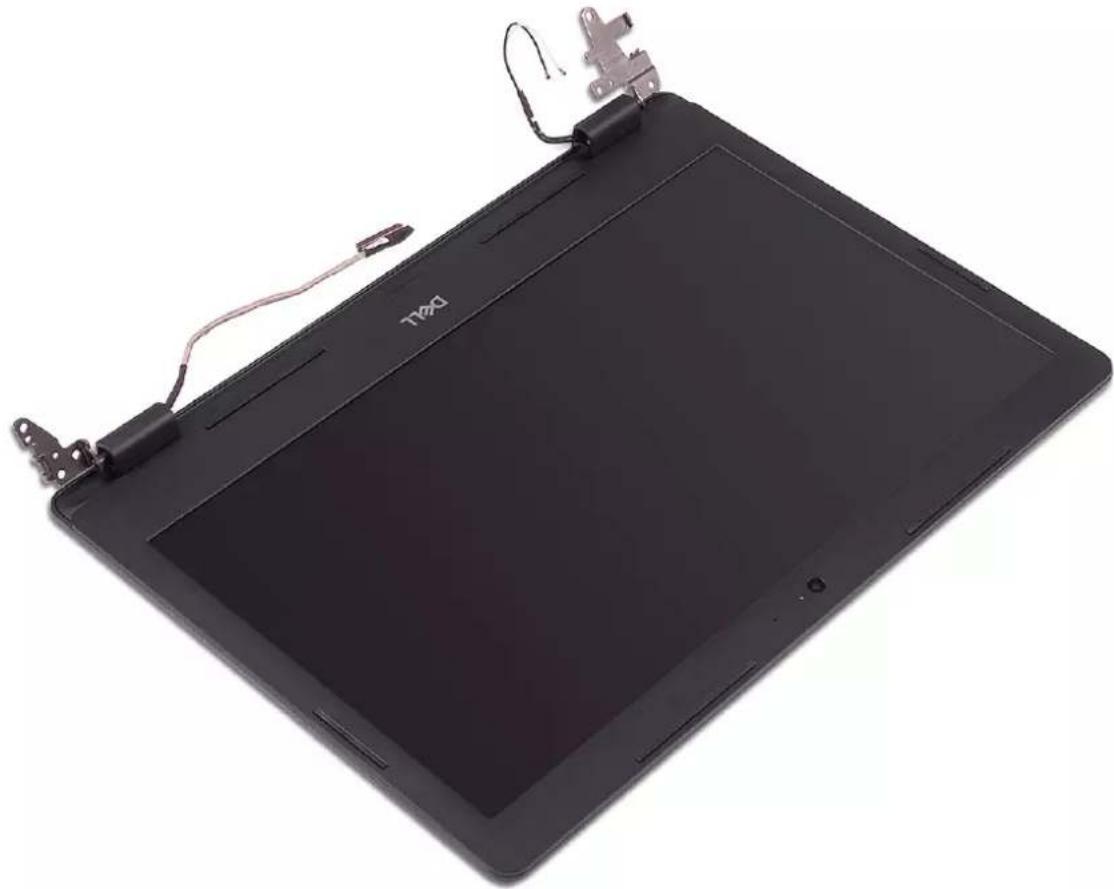
Close-up of hands installing a Dell 42.8Wh battery into a laptop case, showing internal components and wiring (no text or symbols visible)- After performing all the above steps, you are left with display assembly.
natural_image
Black digital tablet with a white 'T20' logo and attached cable, shown against a plain white background (no text or symbols on the device body)Replacing the display assembly
NOTE: Before working inside your computer, read the safety information that shipped with your computer and follow the steps in Before working inside your computer. After working inside your computer, follow the instructions in After working inside your computer. For more safety best practices, see the Regulatory Compliance home page at www.dell.com/regulatory_compliance.
Procedure
NOTE: Ensure that the hinges are opened to the maximum before replacing the display assembly on the palm-rest and keyboard assembly.
- Place the palm-rest and keyboard assembly under the hinges on the display assembly.
- Press the hinges down on the system board and I/O board.
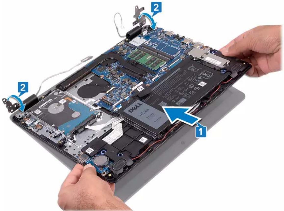
text_image
Labeled diagram of a device showing battery pack assembly with hand and ear, highlighting components 1 and 2.- Replace the four screws (M2.5x4) that secure the display hinges to the system board and I/O board.
- Route the display cable through the routing guides on the palm-rest and keyboard assembly.
- Connect the display cable to the system board.
- Adhere the antenna cables to the system board.
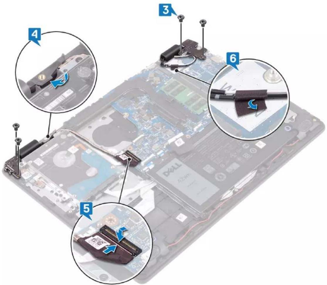
text_image
Laptop chassis interior with numbered annotations indicating component disassembly and assembly stepsPost-requisites
- Replace the fan.
- Replace the wireless card.
- Replace the base cover.
Removing the power-button board

NOTE: Before working inside your computer, read the safety information that shipped with your computer and follow the steps in Before working inside your computer. After working inside your computer, follow the instructions in After working inside your computer. For more safety best practices, see the Regulatory Compliance home page at www.dell.com/regulatory_compliance.
Prerequisites
- Remove the base cover.
- Remove the battery.
- Remove the wireless card.
- Remove the fan.
- Remove the hard drive.
- Remove the display assembly.
Procedure
- Open the latch and disconnect the power-button board cable from the system board.
- Remove the two screws (M2x3) that secure the power-button board to the palm rest and keyboard assembly.
- Lift the power-button board, along with the cable, off the palm rest and keyboard assembly.
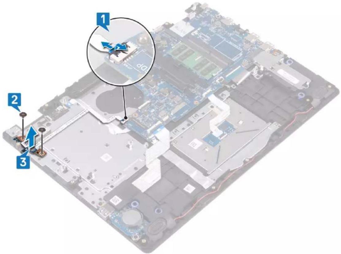
text_image
Labeled diagram of a computer motherboard showing three numbered components with annotations and a magnified inset highlighting a specific component.Replacing the power-button board

NOTE: Before working inside your computer, read the safety information that shipped with your computer and follow the steps in Before working inside your computer. After working inside your computer, follow the instructions in After working inside your computer. For more safety best practices, see the Regulatory Compliance home page at www.dell.com/regulatory_compliance.
Procedure
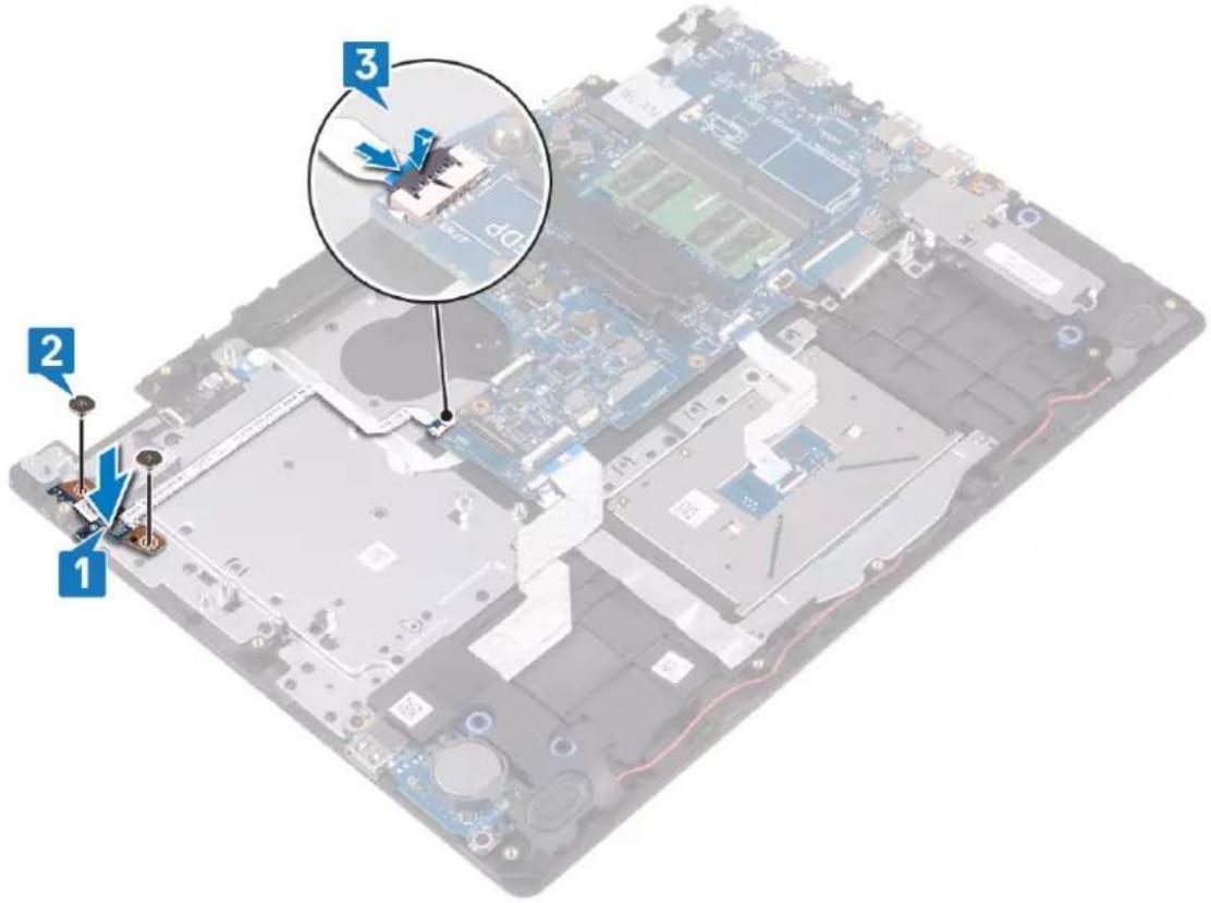
- Place the power-button board into the slot on the palm rest and keyboard assembly.
- Replace the two screws (M2x3) that secure the power-button board to the palm rest and keyboard assembly.
- Slide the power-button cable to the system board and close the latch to secure the cable.
text_image
Labeled diagram of an electronic device showing components and parts with numbered annotationsPost-requisites
- Replace the display assembly.
- Replace the hard drive.
- Replace the fan.
- Replace the wireless card.
- Replace the battery.
- Replace the base cover.
Removing the system board
NOTE: Before working inside your computer, read the safety information that shipped with your computer and follow the steps in Before working inside your computer. After working inside your computer, follow the instructions in After working inside your computer. For more safety best practices, see the Regulatory Compliance home page at www.dell.com/regulatory_compliance.
NOTE: Your computer's Service Tag is stored in the system board. You must enter the Service Tag in the BIOS setup program after you replace the system board.
NOTE: Replacing the system board removes any changes you have made to the BIOS using the BIOS setup program. You must make the appropriate changes again after you replace the system board.
NOTE: Before disconnecting the cables from the system board, note the location of the connectors so that you can reconnect the cables correctly after you replace the system board.
Prerequisites
- Remove the base cover.
- Remove the battery.
- Remove the memory modules.
- Remove the wireless card.
- Remove the fan.
- Remove the heat sink.
- Remove the solid-state drive/Intel Optane.
Procedure
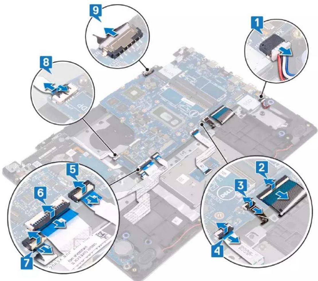
- Disconnect the speaker cable from the system board.
- Open the latch and disconnect the keyboard from the system board.
- Open the latch and disconnect the keyboard back-light cable from the system board.
- Open the latch and disconnect the touchpad cable from the system board.
- Open the latch and disconnect the hard-drive cable from the system board.
- Open the latch and disconnect the I/O board cable from the system board.
- Open the latch and disconnect the finger-print reader cable from the system board.
- Open the latch and disconnect the power-button board cable from the system board.
- Disconnect the power-adapter port cable from the system board.
text_image
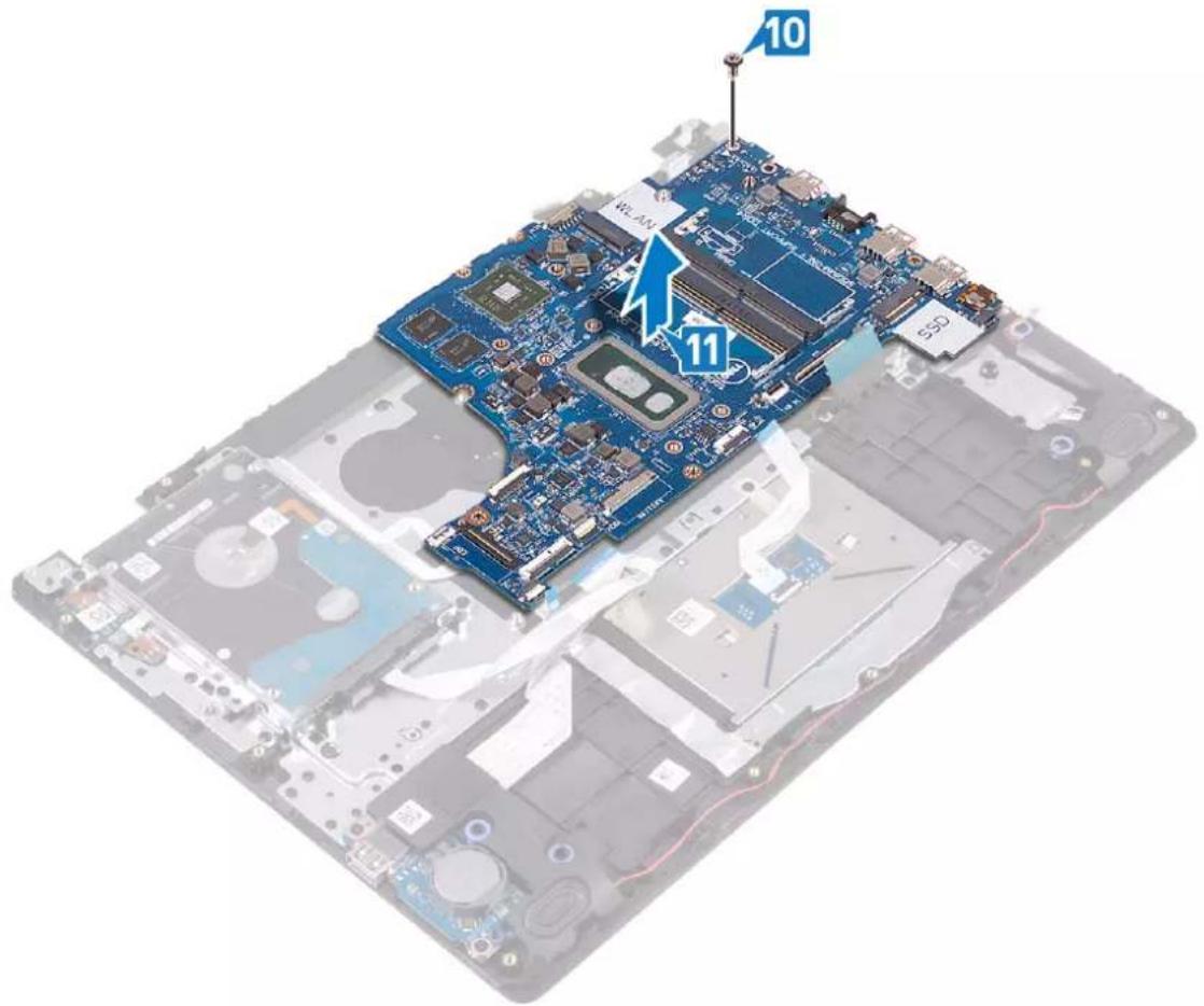
Diagram of computer motherboard with numbered annotations indicating component locations and connections- Remove the screw (M2x4) that secures the system board to the palm-rest and keyboard assembly.
- Lift the system board off the palm-rest and keyboard assembly.
text_image
10 W-AM 11 550Replacing the system board
NOTE: Before working inside your computer, read the safety information that shipped with your computer and follow the steps in Before working inside your computer. After working inside your computer, follow the instructions in After working inside your computer. For more safety best practices, see the Regulatory Compliance home page at www.dell.com/regulatory_compliance.
NOTE: Your computer's Service Tag is stored in the system board. You must enter the Service Tag in the BIOS setup program after you replace the system board.
NOTE: Replacing the system board removes any changes you have made to the BIOS using the BIOS setup program. You must make the appropriate changes again after you replace the system board.
Procedure
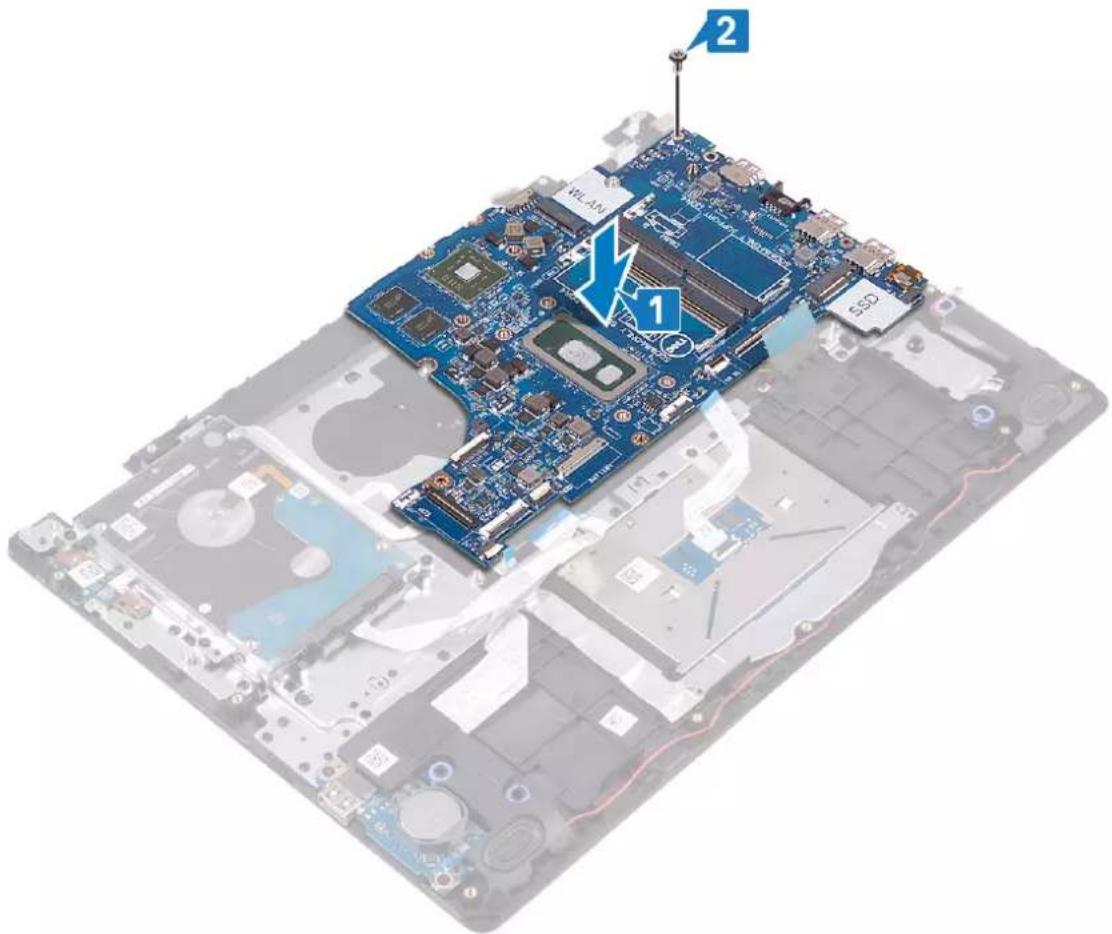
- Align the screw hole on the system board with the screw hole on the palm-rest and keyboard assembly.
- Replace the screw (M2x4) that secures the system board to the palm rest and keyboard assembly.
text_image
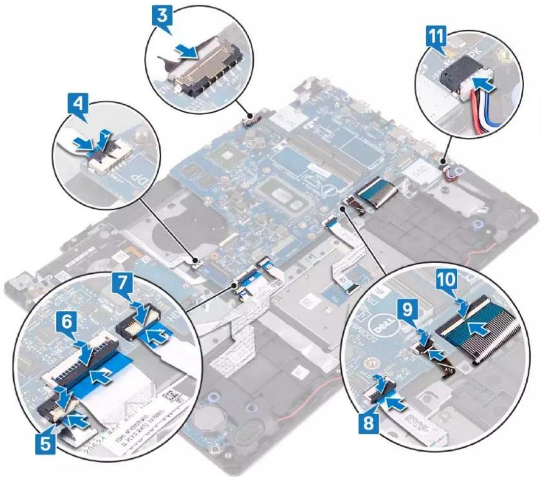
Exploded view of a computer motherboard with labeled components and a blue lightning bolt indicating a specific area.- Connect the power-adapter port cable and speaker cable to the system board.
- Slide the power-button board cable into the connector on the system board and close the latch to secure the cable.
- Slide the finger-print reader cable into the connector on the system board and close the latch to secure the cable.
-
Slide the I/O-board cable into the connector on the system board and close the latch to secure the cable.
-
Slide the hard-drive cable into the connector on the system board and close the latch to secure the cable.
- Slide the touchpad cable into the connector on the system board and close the latch to secure the cable.
- Slide the keyboard back-light cable into the connector on the system board and close the latch to secure the cable.
- Slide the keyboard cable into the connector on the system board and close the latch to secure the cable.
- Connect the speaker cable to the system board.
text_image
Labeled diagram of a computer motherboard showing numbered components with annotations for assembly or repair steps.Post-requisites
- Replace the solid-state drive/Intel Optane.
- Replace the heat sink.
- Replace the fan.
- Replace the wireless card.
- Replace the memory modules.
- Replace the battery.
- Replace the base cover.
Entering the Service Tag in the BIOS setup program
- Turn on or restart your computer.
- Press F2 when the Dell logo is displayed to enter the BIOS setup program.
- Navigate to the Main tab and enter the Service Tag in the Service Tag Input field.
NOTE: Service tag is the alphanumeric identifier located at the back side of your computer.
Removing the power button with fingerprint reader
NOTE: Before working inside your computer, read the safety information that shipped with your computer and follow the steps in Before working inside your computer. After working inside your computer, follow the instructions in After working inside your computer. For more safety best practices, see the Regulatory Compliance home page at www.dell.com/regulatory_compliance.
NOTE: Applicable only for computers that are shipped with fingerprint reader.
Prerequisites
- Remove the base cover.
- Remove the battery.
- Remove the memory modules.
- Remove the wireless card.
- Remove the fan.
- Remove the heat sink.
- Remove the solid-state drive/Intel Optane.
- Remove the hard drive.
- Remove the display assembly.
- Remove the system board.
Procedure
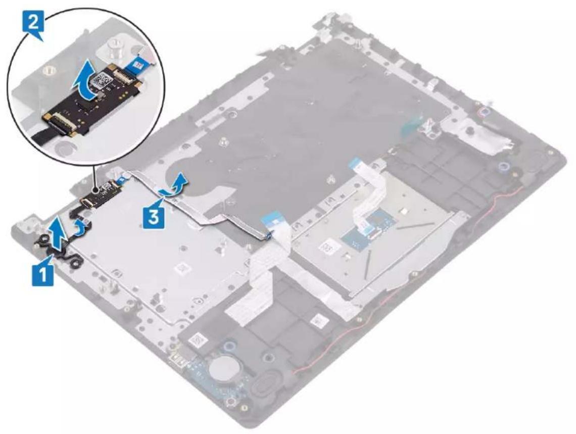
- Lift the power button off the palm rest and keyboard assembly.
- Lift the power-button with fingerprint-reader board off the palm rest and keyboard assembly.
- Peel the fingerprint reader cable off the palm rest and keyboard assembly.
text_image
Labeled diagram of a computer motherboard showing component assembly with numbered annotationsReplacing the power button with fingerprint reader
NOTE: Before working inside your computer, read the safety information that shipped with your computer and follow the steps in Before working inside your computer. After working inside your computer, follow the instructions in After working inside your computer. For more safety best practices, see the Regulatory Compliance home page at www.dell.com/regulatory_compliance.
NOTE: Applicable only for computers that are shipped with fingerprint reader.
Procedure
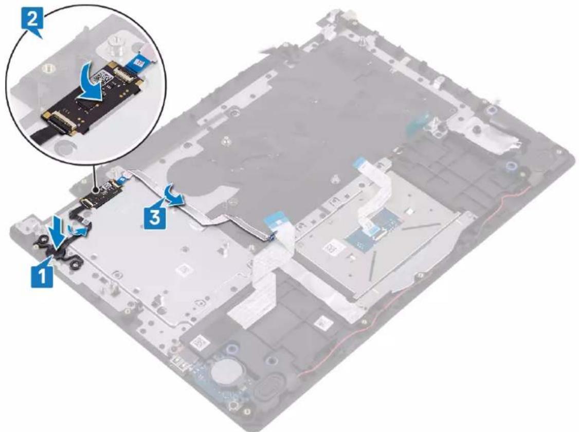
- Using the alignment posts, align and place the power button on the palm rest and keyboard assembly.
- Place the power-button with fingerprint-reader board onto the slot on the palm rest and keyboard assembly.
- Adhere the fingerprint reader cable on the palm rest and keyboard assembly.
text_image
Laptop screen with labeled components and a magnified inset showing cable connector detailsPost-requisites
- Replace the system board.
- Replace the display assembly.
- Replace the hard drive.
-
Replace the solid-state drive/Intel Optane.
-
Replace the heat sink.
- Replace the fan.
- Replace the wireless card.
- Replace the memory modules.
- Replace the battery.
- Replace the base cover.
Removing the power-adapter port

NOTE: Before working inside your computer, read the safety information that shipped with your computer and follow the steps in Before working inside your computer. After working inside your computer, follow the instructions in After working inside your computer. For more safety best practices, see the Regulatory Compliance home page at www.dell.com/regulatory_compliance.
Prerequisites
- Remove the base cover.
- Remove the battery.
- Remove the memory modules.
- Remove the wireless card.
- Remove the fan.
- Remove the heat sink.
- Remove the solid-state drive/Intel Optane.
- Remove the hard drive.
- Remove the display assembly.
- Remove the system board.
Procedure
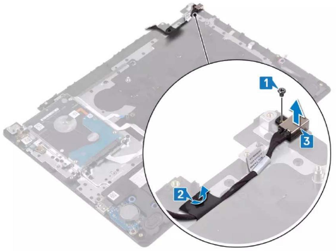
- Remove the screw (M2x2) that secures the power-adapter port to the palm rest and keyboard assembly.
- Peel off the power-adapter port cable from the palm-rest and keyboard assembly.
- Lift the power-adapter port, along with its cable, off the palm rest and keyboard assembly.
text_image
Diagram showing a device with labeled parts and a magnified inset highlighting three numbered components.Replacing the power-adapter port

NOTE: Before working inside your computer, read the safety information that shipped with your computer and follow the steps in Before working inside your computer. After working inside your computer, follow the instructions in After working inside your computer. For more safety best practices, see the Regulatory Compliance home page at www.dell.com/regulatory_compliance.
Procedure
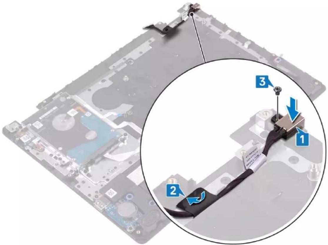
- Place the power-adapter port into the slot on the palm rest and keyboard assembly.
- Adhere the power-adapter port cable to the palm-rest and keyboard assembly.
- Replace the screw (M2x2) that secures the power-adapter port to the palm rest and keyboard assembly.
text_image
Diagram showing a device with labeled parts and a magnified inset highlighting component 1, 2, and 3.Post-requisites
- Replace the system board.
- Replace the display assembly.
- Replace the hard drive.
- Replace the solid-state drive/Intel Optane.
- Replace the heat sink.
- Replace the fan.
- Replace the wireless card.
-
Replace the memory modules.
-
Replace the battery.
- Replace the base cover.
Removing the palm-rest and keyboard assembly

NOTE: Before working inside your computer, read the safety information that shipped with your computer and follow the steps in Before working inside your computer. After working inside your computer, follow the instructions in After working inside your computer. For more safety best practices, see the Regulatory Compliance home page at www.dell.com/regulatory_compliance.
Prerequisites
- Remove the base cover.
- Remove the battery.
- Remove the memory modules.
- Remove the wireless card.
- Remove the fan.
- Remove the heat sink.
- Remove the solid-state drive/Intel Optane.
- Remove the hard drive.
- Remove the touchpad.
- Remove the speakers.
- Remove the I/O board.
- Remove the display assembly.
- Remove the power-button board (optional).
- Remove the system board.
- Remove the power button with fingerprint reader (optional).
- Remove the power-adapter port.
Procedure
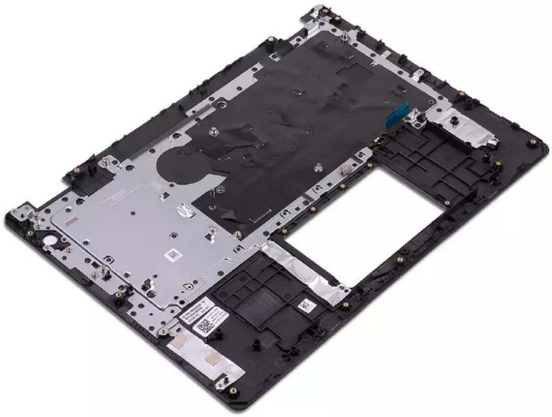
After performing the above steps, we are left with the palm-rest and keyboard assembly.
natural_image
Labeled overhead computer panel showing internal components and mounting holes (no text or symbols visible)Replacing the palm-rest and keyboard assembly

NOTE: Before working inside your computer, read the safety information that shipped with your computer and follow the steps in Before working inside your computer. After working inside your computer, follow the instructions in After working inside your computer. For more safety best practices, see the Regulatory Compliance home page at www.dell.com/regulatory_compliance.
Procedure
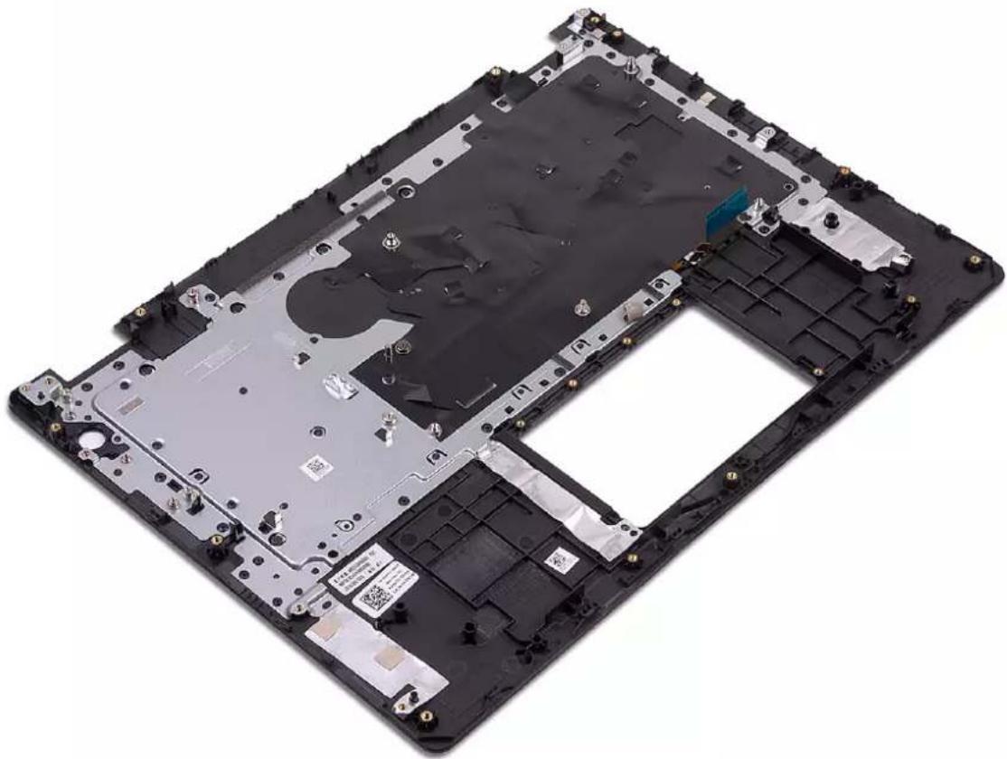
Place the palm-rest and keyboard assembly on a flat surface.
natural_image
Interior view of a black laptop chassis showing exposed circuit board and internal components (no text or symbols visible)Post-requisites
- Replace the power-adapter port.
- Replace the power button with fingerprint reader (optional).
- Replace the system board.
- Replace the power-button board(optional).
- Replace the display assembly.
- Replace the I/O board.
- Replace the speakers.
-
Replace the touchpad.
-
Replace the hard drive.
- Replace the solid-state drive/Intel Optane.
- Replace the heat sink.
- Replace the fan.
- Replace the wireless card.
- Replace the memory modules.
- Replace the battery.
- Replace the base cover.
Removing the display bezel

NOTE: Before working inside your computer, read the safety information that shipped with your computer and follow the steps in Before working inside your computer. After working inside your computer, follow the instructions in After working inside your computer. For more safety best practices, see the Regulatory Compliance home page at www.dell.com/regulatory_compliance.
Prerequisites
- Remove the base cover.
- Remove the wireless card.
- Remove the fan.
- Remove the display assembly.
Procedure
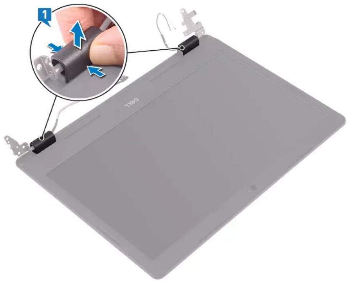
- Push both sides of the display-hinge cover and lift it from the display back-cover and antenna assembly.
natural_image
Illustration of a digital tablet with a hand holding a pen, showing a close-up of the device's cable being inserted (no text or symbols visible)- Pry the display bezel to release it from the display back-cover and antenna assembly.
- Lift the display bezel off the display back-cover and antenna assembly.
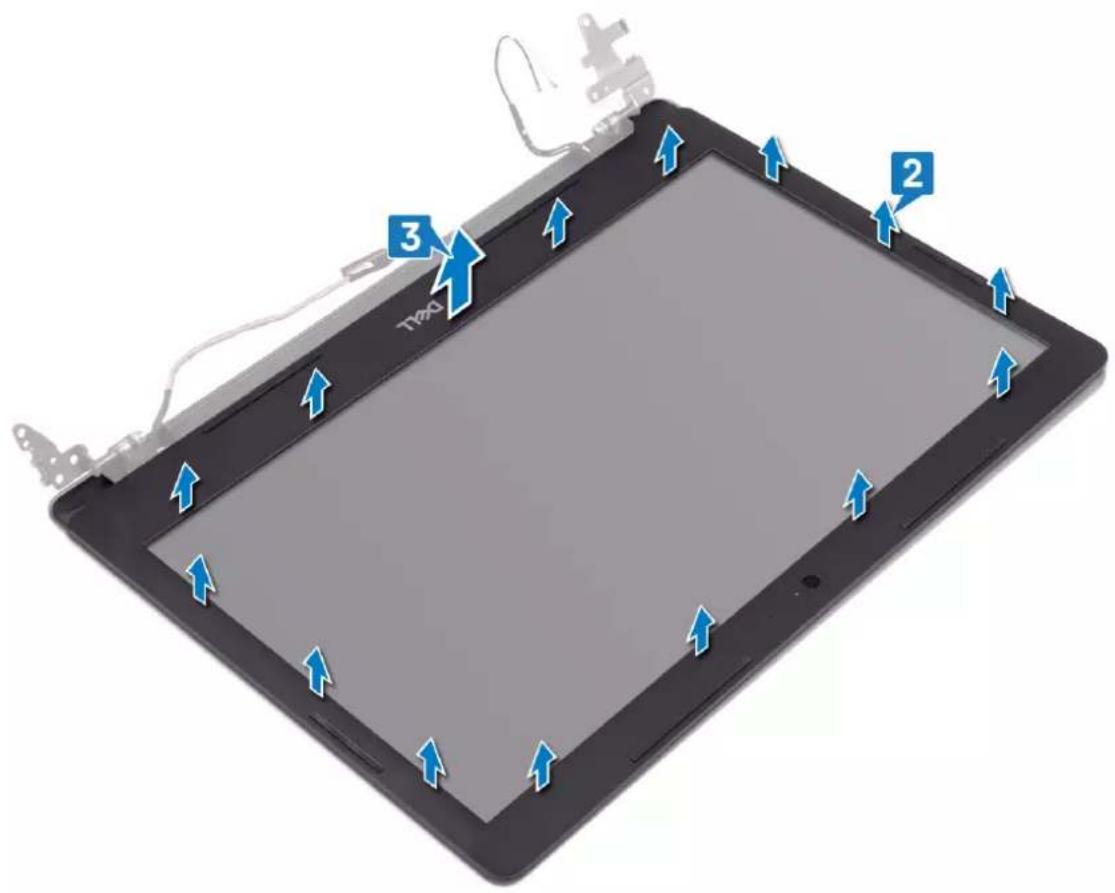
text_image
3 2Replacing the display bezel

NOTE: Before working inside your computer, read the safety information that shipped with your computer and follow the steps in Before working inside your computer. After working inside your computer, follow the instructions in After working inside your computer. For more safety best practices, see the Regulatory Compliance home page at www.dell.com/regulatory_compliance.
Procedure
- Align the display bezel with the display back-cover and antenna assembly, and then gently snap the display bezel into place.
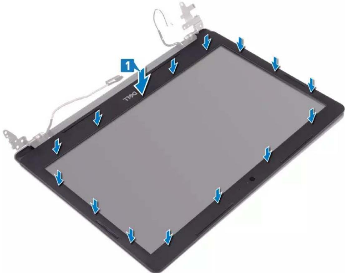
text_image
1 TWO- Insert the tabs on the display-hinge cover to the slots on the display back-cover and antenna assembly.
- Snap the display-hinge cover into place.
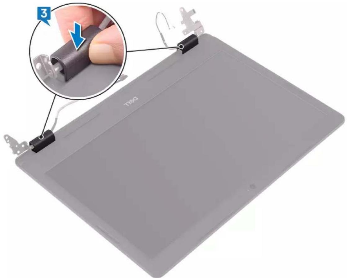
text_image
3 T240Post-requisites
- Replace the display assembly.
- Replace the fan.
- Replace the wireless card.
- Replace the base cover.
Removing the camera

NOTE: Before working inside your computer, read the safety information that shipped with your computer and follow the steps in Before working inside your computer. After working inside your computer, follow the instructions in After working inside your computer. For more safety best practices, see the Regulatory Compliance home page at www.dell.com/regulatory_compliance.
Prerequisites
- Remove the base cover.
- Remove the wireless card.
- Remove the fan.
- Remove the display assembly.
- Remove the display bezel.
Procedure
- Using a plastic scribe, gently pry the camera off the display back-cover and antenna assembly.
- Disconnect the camera cable from the camera module.
- Lift the camera module from the display back-cover and antenna assembly.
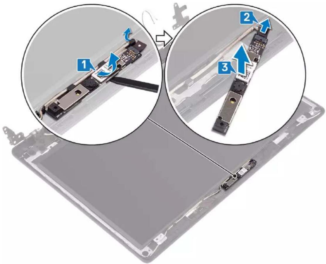
text_image
Diagram showing three views of a device with labeled components and directional arrows indicating assembly or repair steps.Replacing the camera

NOTE: Before working inside your computer, read the safety information that shipped with your computer and follow the steps in Before working inside your computer. After working inside your computer, follow the instructions in After working inside your computer. For more safety best practices, see the Regulatory Compliance home page at www.dell.com/regulatory_compliance.
Procedure
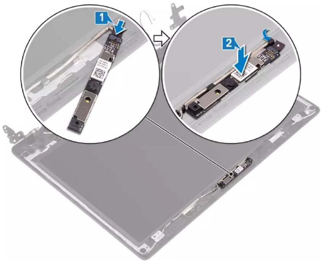
- Connect the camera cable to the camera module.
- Using the alignment post, adhere the camera module on the display back-cover and antenna assembly.
text_image
Technical diagram showing two views of a device with labeled components and blue arrows indicating steps 1 and 2.Post-requisites
- Replace the display bezel.
- Replace the display assembly.
- Replace the fan.
- Replace the wireless card.
- Replace the base cover.
Removing the display panel

NOTE: Before working inside your computer, read the safety information that shipped with your computer and follow the steps in Before working inside your computer. After working inside your computer, follow the instructions in After working inside your computer. For more safety best practices, see the Regulatory Compliance home page at www.dell.com/regulatory_compliance.
Prerequisites
- Remove the base cover.
- Remove the wireless card.
- Remove the fan.
- Remove the display assembly.
- Remove the display bezel.
Procedure
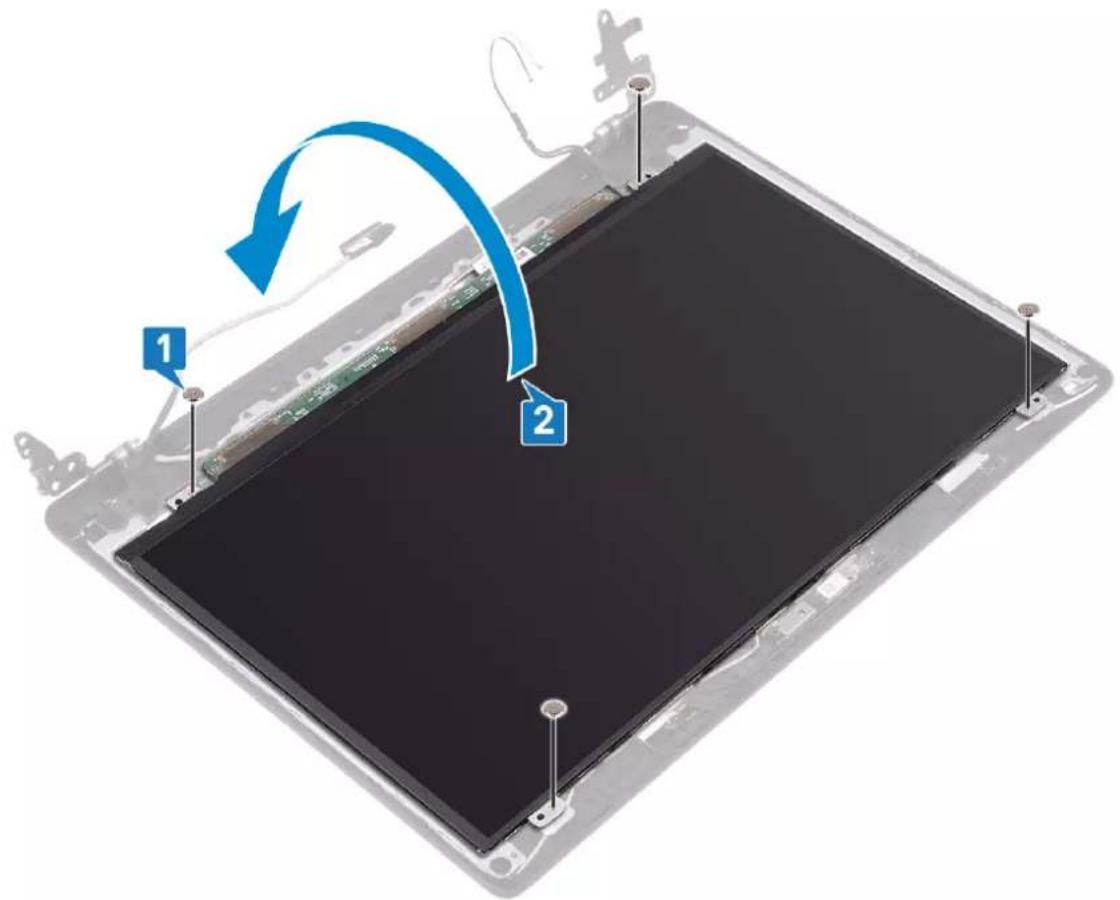
- Remove the four screws (M2x2) that secure the display panel to the display back-cover and antenna assembly.
- Lift the display panel and turn it over.
text_image
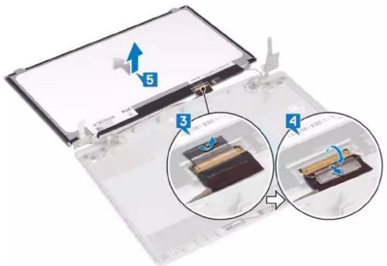
Diagram showing a device with labeled components and a blue curved arrow indicating rotation or change.- Peel the tape that secures the display cable to the back of the display panel.
-
Lift the latch and disconnect the display cable from the display-panel cable connector.
-
Lift the display panel away from the display back-cover and antenna assembly.
text_image
Diagram showing a device with labeled components and directional arrows indicating motion or assembly stepsReplacing the display panel

NOTE: Before working inside your computer, read the safety information that shipped with your computer and follow the steps in Before working inside your computer. After working inside your computer, follow the instructions in After working inside your computer. For more safety best practices, see the Regulatory Compliance home page at www.dell.com/regulatory_compliance.
Procedure
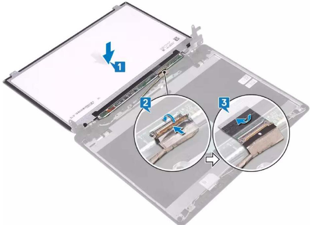
- Place the display panel on a flat and clean surface.
- Connect the display cable to the connector at the back of the display panel and close the latch to secure the cable.
- Adhere the tape that secures the display cable to the back of the display panel.
text_image
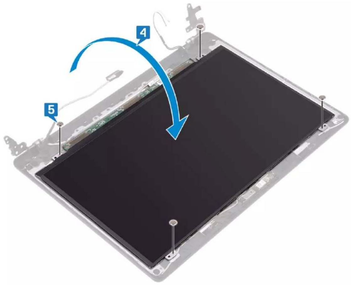
Diagram showing three-step assembly process of a laptop with labeled steps and arrows indicating motion direction.- Turn the display panel over and place it on the display back-cover and antenna assembly.
- Align the screw holes on the display panel with the screw holes on the display back-cover and antenna assembly.
- Replace the screws that secure the display panel to the display back-cover and antenna assembly.
text_image
4 5Post-requisites
- Replace the display bezel.
- Replace the display assembly.
- Replace the fan.
- Replace the wireless card.
- Replace the base cover.
Removing the display hinges

NOTE: Before working inside your computer, read the safety information that shipped with your computer and follow the steps in Before working inside your computer. After working inside your computer, follow the instructions in After working inside your computer. For more safety best practices, see the Regulatory Compliance home page at www.dell.com/regulatory_compliance.
Prerequisites
- Remove the base cover.
- Remove the wireless card.
- Remove the fan.
- Remove the display assembly.
- Remove the display bezel.
Procedure
- Remove the 10 screws (M2x2) that secure the hinges to the display back-cover and antenna assembly.
- Lift the hinges and brackets off the display back-cover and antenna assembly.

text_image
Diagram of an electronic device with labeled components and directional arrows indicating assembly or movement.Replacing the display hinges

NOTE: Before working inside your computer, read the safety information that shipped with your computer and follow the steps in Before working inside your computer. After working inside your computer, follow the instructions in After working inside your computer. For more safety best practices, see the Regulatory Compliance home page at www.dell.com/regulatory_compliance.
Procedure
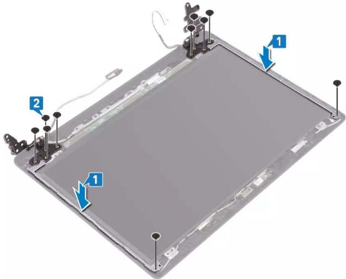
- Align the screw holes on the hinges and brackets with the screw holes on the display back-cover and antenna assembly.
- Replace the 10 screws (M2x2) that secure the hinges to the display back-cover and antenna assembly.
text_image
Diagram of an electronic device with labeled components and directional arrows indicating assembly or status.Post-requisites
- Replace the display bezel.
- Replace the display assembly.
- Replace the fan.
- Replace the wireless card.
- Replace the base cover.
Removing the display cable

NOTE: Before working inside your computer, read the safety information that shipped with your computer and follow the steps in Before working inside your computer. After working inside your computer, follow the instructions in After working inside your computer. For more safety best practices, see the Regulatory Compliance home page at www.dell.com/regulatory_compliance.
Prerequisites
- Remove the base cover.
- Remove the fan.
- Remove the wireless card.
- Remove the display assembly.
- Remove the display bezel.
- Remove the camera.
- Remove the display panel.
- Remove the display hinges.
Procedure
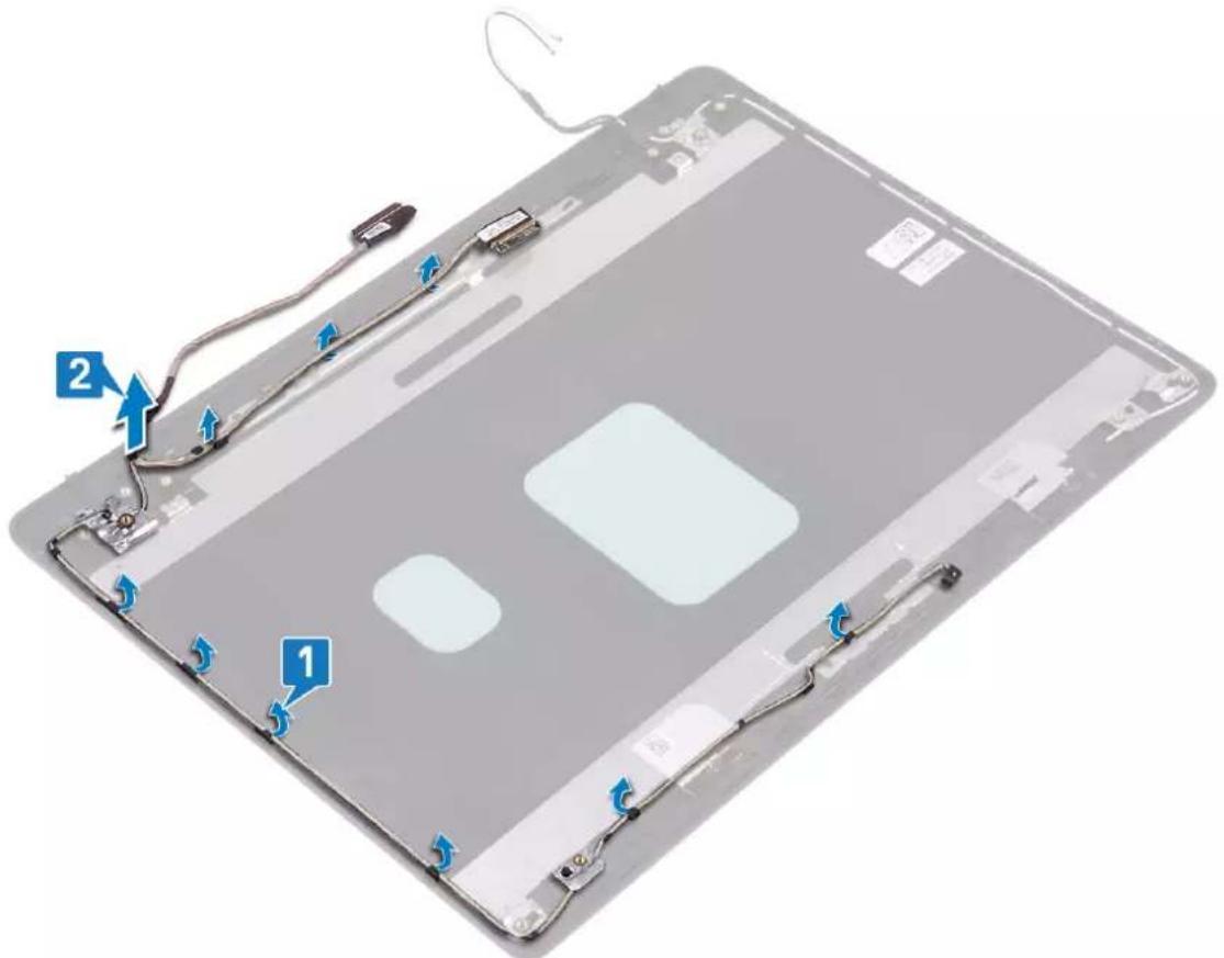
- Remove the camera cable and the display cable from the routing guides on the display back-cover and antenna assembly.
- Lift the camera cable and the display cable off the display back-cover and antenna assembly.
text_image
Labeled diagram of an electronic device showing components with numbered annotations pointing to parts 1 and 2.Replacing the display cable

NOTE: Before working inside your computer, read the safety information that shipped with your computer and follow the steps in Before working inside your computer. After working inside your computer, follow the instructions in After working inside your computer. For more safety best practices, see the Regulatory Compliance home page at www.dell.com/regulatory_compliance.
Procedure
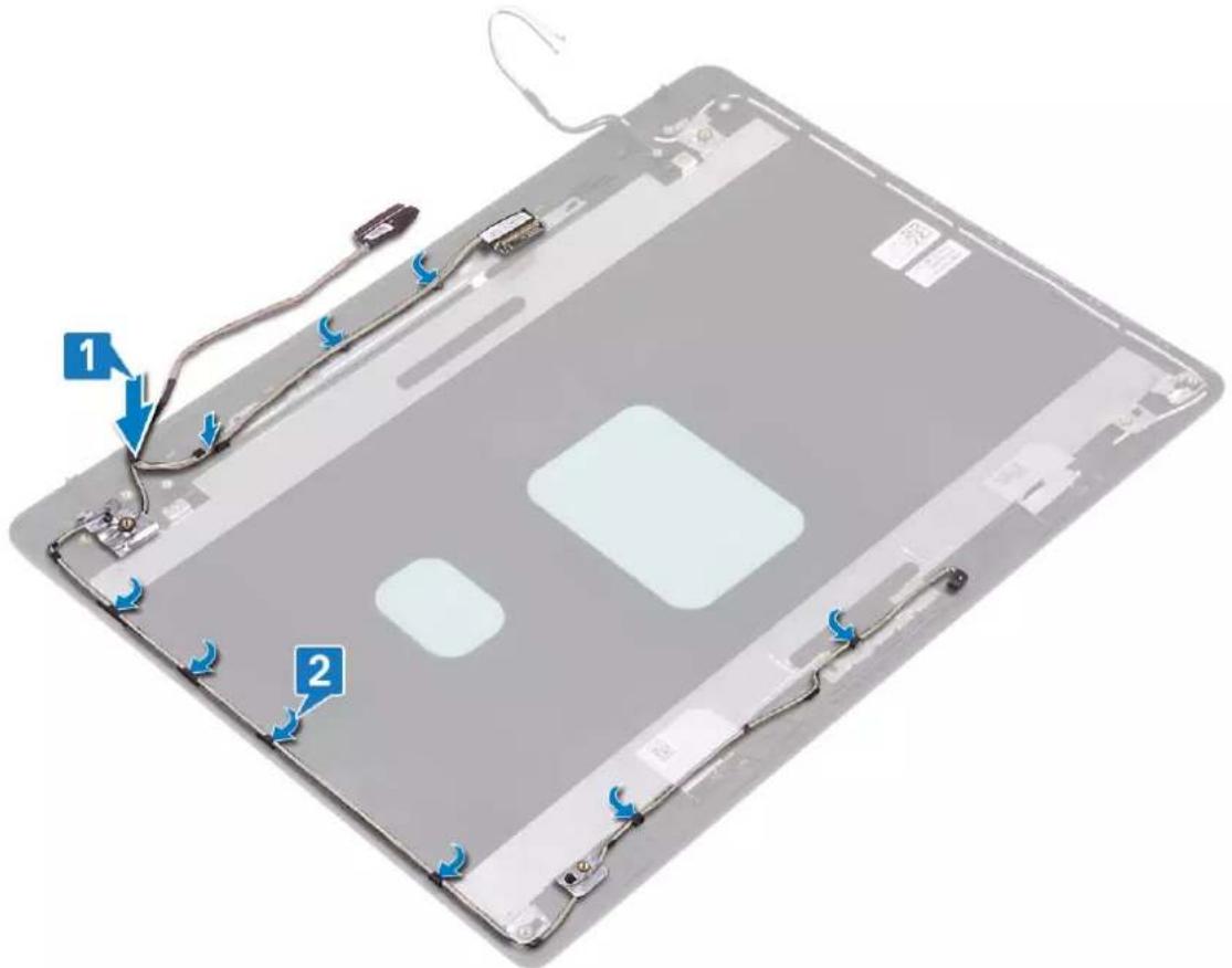
- Place the display cable and camera cable on the display back-cover and antenna assembly.
- Route the display cable and camera cable through the routing guides on the display back-cover and antenna assembly.
text_image
Labeled diagram of a tablet device showing two numbered components with cable and connectorsPost-requisites
- Replace the display hinges.
- Replace the display panel.
- Replace the camera.
- Replace the display bezel.
- Replace the display assembly.
- Replace the fan.
-
Replace the wireless card.
-
Replace the base cover.
Removing the display back-cover and antenna assembly

NOTE: Before working inside your computer, read the safety information that shipped with your computer and follow the steps in Before working inside your computer. After working inside your computer, follow the instructions in After working inside your computer. For more safety best practices, see the Regulatory Compliance home page at www.dell.com/regulatory_compliance.
Prerequisites
- Remove the base cover.
- Remove the wireless card.
- Remove the fan.
- Remove the display assembly.
- Remove the display bezel.
- Remove the camera.
- Remove the display panel.
- Remove the display hinges.
- Remove the display cable.
Procedure
After performing all the above steps, we are left with the display back-cover and antenna assembly.
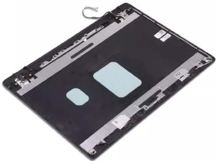
natural_image
Top-down view of a black electronic device with visible circuitry and a light blue internal component (no text or symbols)Replacing the display back-cover and antenna assembly

NOTE: Before working inside your computer, read the safety information that shipped with your computer and follow the steps in Before working inside your computer. After working inside your computer, follow the instructions in After working inside your computer. For more safety best practices, see the Regulatory Compliance home page at www.dell.com/regulatory_compliance.
Procedure
Place the display back-cover and antenna assembly on a clean and flat surface.

natural_image
Top-down view of a black electronic device with visible circuitry and a light blue internal component (no text or symbols)Post-requisites
- Replace the display cable.
- Replace the display hinges.
- Replace the display panel.
- Replace the camera.
- Replace the display bezel.
- Replace the display assembly.
- Replace the fan.
- Replace the wireless card.
- Replace the base cover.
Intel Chipset Software Installation Utility
In the Device Manager, check if the chipset driver is installed.
Install the Intel chipset updates from www.dell.com/support.
Video drivers
In the Device Manager, check if the video driver is installed.
Install the video driver update from www.dell.com/support.
Intel Serial IO driver
In the Device Manager, check if the Intel Serial IO driver is installed.
Install the driver updates from www.dell.com/support.
Intel Trusted Execution Engine Interface
In the Device Manager, check if the Intel Trusted Execution Engine Interface driver is installed.
Install the driver update from www.dell.com/support.
Intel Virtual Button driver
In the Device Manager, check if the Intel Virtual Button driver is installed.
Install the driver updates from www.dell.com/support.
Wireless and Bluetooth drivers
In the Device Manager, check if the network card driver is installed.
Install the driver updates from www.dell.com/support.
In the Device Manager, check if the Bluetooth driver is installed.
Install the driver updates from www.dell.com/support.
System setup
NOTE: Depending on the computer and its installed devices, the items listed in this section may or may not be displayed.
System setup
CAUTION: Unless you are an expert computer user, do not change the settings in the BIOS Setup program. Certain changes can make your computer work incorrectly.
NOTE: Before you change BIOS Setup program, it is recommended that you write down the BIOS Setup program screen information for future reference.
Use the BIOS Setup program for the following purposes:
• Get information about the hardware installed in your computer, such as the amount of RAM and the size of the hard drive.
- Change the system configuration information.
- Set or change a user-selectable option, such as the user password, type of hard drive installed, and enabling or disabling base devices.
Entering BIOS setup program
- Turn on (or restart) your computer.
- During POST, when the DELL logo is displayed, watch for the F2 prompt to appear, and then press F2 immediately.
NOTE: The F2 prompt indicates that the keyboard is initialized. This prompt can appear very quickly, so you must watch for it, and then press F2. If you press F2 before the F2 prompt, this keystroke is lost. If you wait too long and the operating system logo appears, continue to wait until you see the desktop. Then, turn off your computer and try again.
Navigation keys
NOTE: For most of the System Setup options, changes that you make are recorded but do not take effect until you restart the system.
Keys Navigation
Up arrow Moves to the previous field.
Down arrow Moves to the next field.
Enter Selects a value in the selected field (if applicable) or follow the link in the field.
Spacebar Expands or collapses a drop-down list, if applicable.
Tab Moves to the next focus area.
NOTE: For the standard graphics browser only.
Esc Moves to the previous page until you view the main screen. Pressing Esc in the main screen displays a message that prompts you to save any unsaved changes and restarts the system.
Boot Sequence
Boot Sequence allows you to bypass the System Setup-defined boot device order and boot directly to a specific device (for example: optical drive or hard drive). During the Power-on Self Test (POST), when the Dell logo appears, you can:
- Access System Setup by pressing F2 key
- Bring up the one-time boot menu by pressing F12 key
The one-time boot menu displays the devices that you can boot from including the diagnostic option. The boot menu options are:
- Removable Drive (if available)
- STXXXX Drive

NOTE: XXX denotes the SATA drive number.
• Optical Drive (if available)
• SATA Hard Drive (if available)
• Diagnostics

NOTE: Choosing Diagnostics, will display the ePSA diagnostics screen.
The boot sequence screen also displays the option to access the System Setup screen.
System setup options

NOTE: Depending on this computer and its installed devices, the items listed in this section may or may not appear.
Table 3. System setup options—System information menu
| General-System Information | |
| System Information | |
| BIOS Version Displays the BIOS version number. | |
| Service Tag Displays the Service Tag of the computer. | |
| Asset Tag Displays the Asset Tag of the computer. | |
| Ownership Tag Displays the ownership tag of the computer. | |
| Manufacture Date Displays the manufacture date of the computer. | |
| Ownership Date Displays the ownership date of the computer. | |
| Express Service Code Displays the express service code of the computer. | |
| Memory Information | |
| Memory Installed Displays the total computer memory installed. | |
| Memory Available Displays the total computer memory available. | |
| Memory Speed Displays the memory speed. | |
| Memory Channel Mode Displays single or dual channel mode. | |
| Memory Technology Displays the technology used for the memory. | |
| DIMM A Size Displays the DIMM A memory size. | |
| DIMM B Size Displays the DIMM B memory size. | |
| Processor Information | |
| Processor Type Displays the processor type. | |
| Core Count Displays the number of cores on the processor. | |
| Processor ID | Displays the processor identification code. |
| Current Clock Speed | Displays the current processor clock speed. |
| Minimum Clock Speed | Displays the minimum processor clock speed. |
| Maximum Clock Speed | Displays the maximum processor clock speed. |
| Processor L2 Cache | Displays the processor L2 Cache size. |
| Processor L3 Cache | Displays the processor L3 Cache size. |
| HT Capable | Displays whether the processor is HyperThreading (HT) capable. |
| 64-Bit Technology Displays whether 64-bit technology is used. | |
| Device Information | |
| SATA-0 Displays the M.2 SATA SSD-0 device information of the computer. | |
| SATA-1 Displays the M.2 SATA SSD-1 device information of the computer. | |
| M.2 PCIe SSD-0 Displays the M.2 PCIe SSD-0 device information of the computer. | |
| M.2 PCIe SSD-1 Displays the M.2 PCIe SSD-1 device information of the computer. | |
| Video Controller Displays the video controller type of the computer. | |
| dGPU Video Controller Displays the discrete graphics information of the computer. | |
| Video BIOS Version Displays the video BIOS version of the computer. | |
| Video Memory Displays the video memory information of the computer. | |
| Panel Type Displays the Panel Type of the computer. | |
| Native Resolution Displays the native resolution of the computer. | |
| Audio Controller Displays the audio controller information of the computer. | |
| Wi-Fi Device Displays the wireless device information of the computer. | |
| Bluetooth Device Displays the bluetooth device information of the computer. | |
| Battery Information Displays the battery health information. | |
| Boot Sequence | |
| Boot Sequence Displays the boot sequence. | |
| Boot List Option Displays the available boot options. | |
| Advanced Boot Options | |
| Enable Legacy Option ROMs Enable or disable the Legacy Option ROMs. | |
| Enable UEFI Network Stack | Enable or disable the UEFI Network Stack. |
| Enable Attempt Legacy Boot | Enable or disable Legacy Boot. |
| UEFI Boot Path Security | Enable or disable the system to prompt the user to enter the Admin password when booting a UEFI boot path from the F12 boot menu. |
| Date/Time | Displays the current date in MM/DD/YY format and current time in HH:MM:SS AM/PM format. |
Table 4. System setup options—System Configuration menu
| System Configuration | |
| SATA Operation | Configure operating mode of the integrated SATA hard drive controller. |
| Drives | Enable or disable various drives on board. |
| SMART Reporting | Enable or disable SMART Reporting during system startup. |
| USB Configuration | |
| Enable Boot Support | Enable or disable booting from USB mass storage devices such as external hard drive, optical drive, and USB drive. |
| Enable External USB Port | Enable or disable booting from USB mass storage devices connected to external USB port. |
| Audio | Enable or disable the integrated audio controller. |
| Keyboard Illumination | Enables you to choose the operating mode of the keyboard illumination feature. |
| Keyboard Backlight Timeout on AC | When the backlight is enabled, this feature defines the timeout value for the keyboard backlight when an AC adapter is plugged into the computer. |
| Keyboard Backlight Timeout on Battery | When the backlight is enabled, this feature defines the timeout value for the keyboard backlight when the computer is running only on battery power. |
| Miscellaneous Devices Enable or disable various onboard devices. | |
Table 5. System setup options—Video menu
| Video |
| LCD Brightness Set the panel brightness independently for Battery and AC power. |
| Dynamic Backlight Control Enable or disable the dynamic backlight control. |
Table 6. System setup options—Security menu
| Security | |
| Admin Password Set, change, or delete the administrator password. | |
| System Password Set, change, or delete the system password. | |
| Internal HDD-0 Password Set, change, or delete the internal hard-disk drive password. | |
| Strong Password Enable or disable strong passwords. | |
| Password Configuration Control the minimum and maximum number of characters allowed for Admin and System passwords. | |
| Password Bypass Bypass the System (Boot) Password and the internal HDD password prompts during a system restart. | |
| Password Change Enable or disable changes to the System and Hard Disk passwords when an administrator password is set. | |
| Non-Admin Setup Changes Determines whether changes to the setup option are permitted when an administrator password is set. | |
| UEFI Capsule Firmware Updates Enable or disable BIOS updates through UEFI capsule update packages. | |
| PTT Security Enable or disable Platform Trust Technology (PTT) visibility to the operating system. | |
| Computrace(R) Enable or disable the BIOS module interface of the optional Computrace(R) Service from Absolute Software. | |
| Admin Setup Lockout Enable to prevent users from entering Setup when an Admin Password is set. | |
| Master Password Lockout | Disables the master password support. Hard Disk passwords need to be cleared before changing the setting. |
| SMM Security Mitigation | Enable or disable the SMM Security Mitigation. |
Table 7. System setup options—Secure Boot menu
| Secure Boot | |
| Secure Boot Enable | Enable or disable the secure boot feature. |
| Secure Boot Mode | Modifies the behavior of Secure Boot to allow evaluation or enforcement of UEFI driver signatures. |
| Expert Key Management | |
| Expert Key Management | Enable or disable Expert Key Management. |
| Custom Mode Key Management | Select the custom values for expert key management. |
Table 8. System setup options—Intel Software Guard Extensions menu
Intel Software Guard Extensions
Intel SGX Enable
Enable or disable Intel Software Guard Extensions.
Table 8. System setup options—Intel Software Guard Extensions menu (continued)
Intel Software Guard Extensions
| Enclave Memory Size Set the Intel Software Guard Extensions Enclave Reserve Memory Size. | |
| Performance | |
| Multi Core Support Enable multiple cores. | |
| Default: Enabled. | |
| Intel SpeedStep Enable or disable Intel Speedstep Technology. | |
| Default: Enabled. | |
| NOTE: If enabled, the processor clock speed and core voltage are adjusted dynamically based on the processor load. | |
| C-States Control Enable or disable additional processor sleep states. | |
| Default: Enabled. | |
| Intel TurboBoost Enable or disable Intel TurboBoost mode of the processor. | |
| Default: Enabled. | |
| HyperThread control Enable or disable HyperThreading in the processor. | |
| Default: Enabled. | |
| Power Management | |
| AC Behavior Enables the system to turn on automatically, when AC power is supplied. | |
| Enable Intel Speed Shift Technology Enable or disable Intel Speed Shift Technology. | |
| Auto On Time Enable to set the computer to turn on automatically every day or on a preselected date and time. This option can be configured only if the Auto On Time is set to Everyday, Weekdays or Selected Days. | |
| Default: Disabled. | |
| USB Wake Support Enable the USB devices to wake the computer from Standby. | |
| Block Sleep Enable or disable Block Sleep. | |
| Advanced Battery Charge Configuration Enable Advanced Battery Charge Configuration from the beginning of the day to a specified work period. | |
| Primary Battery Charge Configuration Set the primary battery charge settings with a preselected custom charge start and stop. | |
| Default: Adaptive. | |
| POST Behavior | |
| Adapter Warnings Enable adapter warnings. | |
| Default: Enabled. | |
| Numlock Enable Enables the NumLock function when computer boots. | |
| Fn Lock Options Enable or disable the Fn lock mode. | |
| Fastboot | Enable to set the speed of the boot process. |
| Default: Thorough. | |
| Extend BIOS POST Time | Configure additional pre-boot delay. |
| Full Screen Logo Enable or disable to display full screen logo. | |
| Warnings and Errors | Sets the boot process to pause when Warnings or Errors are detected. |
Table 9. System setup options—Virtualization Support menu
| Virtualization Support |
| Virtualization Specify whether a Virtual Machine Monitor (VMM) can utilize the additionalhardware capabilities provided by Intel Virtualization Technology. |
| VT for Direct I/O Specify whether a Virtual Machine Monitor (VMM) can utilize the additionalhardware capabilities provided by Intel Virtualization Technology for Direct I/O. |
Table 10. System setup options—Wireless menu
| Wireless |
| Wireless Switch Determine which wireless devices can be controlled by the Wireless Switch. |
| Wireless Device Enable Enable or disable internal wireless devices. |
Table 11. System setup options—Maintenance menu
| Maintenance |
| Service Tag Display the system's Service Tag. |
| Asset Tag Create a system Asset Tag. |
| BIOS Downgrade Control flashing of the system firmware to previous revisions. |
| Data Wipe Enable to securely erase data from all internal storage devices. |
| BIOS Recovery Enable the user to recover from certain corrupted BIOS conditions from a recovery file on the user primary hard drive or an external USB key. |
| First Power On Date Disable the First Power On Date |
Table 12. System setup options—System Logs menu
| System Logs |
| BIOS Events Display BIOS events. |
| Thermal Events Display Thermal events. |
| Power Events Display Power events. |
Table 13. System setup options—SupportAssist System Resolution menu
| SupportAssist System Resolution |
| Auto OS Recovery Threshold Control the automatic boot flow for SupportAssist System Resolution Console and for Dell OS Recovery tool. |
| SupportAssist OS Recovery Enable or disable the boot flow for SupportAssist OS Recovery tool in the even of certain system errors. |
Clearing CMOS settings
CAUTION: Clearing CMOS settings will reset the BIOS settings on your computer.
- Remove the base cover.
- Disconnect the battery cable from the system board.
- Remove the coin-cell battery.
- Wait for one minute.
- Replace the coin-cell battery.
- Connect the battery cable to the system board.
- Replace the base cover.
Clearing BIOS (System Setup) and System passwords
To clear the system or BIOS passwords, contact Dell technical support as described at www.dell.com/contactdell.
NOTE: For information on how to reset Windows or application passwords, refer to the documentation accompanying Windows or your application.
Flashing the BIOS
You may need to flash (update) the BIOS when an update is available or when you replace the system board.
Follow these steps to flash the BIOS:
- Turn on your computer.
- Go to www.dell.com/support.
- Click Product support, enter the Service Tag of your computer, and then click Submit.

NOTE: If you do not have the Service Tag, use the auto-detect feature or manually browse for your computer model.
- Click Drivers & downloads > Find it myself.
- Select the operating system installed on your computer.
- Scroll down the page and expand BIOS.
- Click Download to download the latest version of the BIOS for your computer.
- After the download is complete, navigate to the folder where you saved the BIOS update file.
- Double-click the BIOS update file icon and follow the instructions on the screen.
Flashing BIOS (USB key)
- Follow the procedure from step 1 to step 7 in "Flashing the BIOS" to download the latest BIOS setup program file.
- Create a bootable USB drive. For more information see the knowledge base article SLN143196 at www.dell.com/support.
- Copy the BIOS setup program file to the bootable USB drive.
- Connect the bootable USB drive to the computer that needs the BIOS update.
- Restart the computer and press F12 when the Dell logo is displayed on the screen.
- Boot to the USB drive from the One Time Boot Menu.
- Type the BIOS setup program filename and press Enter.
- The BIOS Update Utility appears. Follow the instructions on the screen to complete the BIOS update.
Enhanced Pre-Boot System Assessment (ePSA) diagnostics

CAUTION: Use the ePSA diagnostics to test only your computer. Using this program with other computers may cause invalid results or error messages.
The ePSA diagnostics (also known as system diagnostics) performs a complete check of your hardware. The ePSA is embedded with the BIOS and is launched by the BIOS internally. The embedded system diagnostics provides a set of options for particular devices or device groups allowing you to:
- Run tests automatically or in an interactive mode
- Repeat tests
• Display or save test results - Run thorough tests to introduce additional test options to provide extra information about the failed device(s)
- View status messages that inform you if tests are completed successfully
• View error messages that inform you of problems encountered during testing

NOTE: Some tests for specific devices require user interaction. Always ensure that you are present at the computer terminal when the diagnostic tests are performed.
Running the ePSA diagnostics
- Turn on your computer.
- As the computer boots, press the F12 key as the Dell logo appears.
- On the boot menu screen, select the Diagnostics option.
- Click the arrow at the bottom left corner. Diagnostics front page is displayed.
- Click the arrow in the lower-right corner to go to the page listing. The items detected are listed.
- To run a diagnostic test on a specific device, press Esc and click Yes to stop the diagnostic test.
- Select the device from the left pane and click Run Tests.
- If there are any issues, error codes are displayed. Note the error code and validation number and contact Dell.
System diagnostic lights
Power and battery-status light/hard-drive activity light
Indicates the battery-charge status or the hard-drive activity.

NOTE: Press Fn+H to toggle this light between power and battery-status light and hard-drive activity light.
Hard-drive activity light
Turns on when the computer reads from or writes to the hard drive.

NOTE: Hard-drive activity light is supported only on computers shipped with hard drive.
Power and battery-status light
Indicates the power and battery-charge status
Solid white — Power adapter is connected and the battery has more than 5 percent charge.
Amber — Computer is running on battery and the battery has less than 5 percent charge.
Off
- Power adapter is connected and the battery is fully charged.
- Computer is running on battery and the battery has more than 5 percent charge.
- Computer is in sleep state, hibernation, or turned off

NOTE: Hard-drive activity light is supported only on computers shipped with hard drive.
The power and battery-status light blinks amber along with beep codes indicating failures.
For example, the power and battery-status light blinks amber two times followed by a pause, and then blinks white three times followed by a pause. This 2,3 pattern continues until the computer is turned off indicating no memory or RAM is detected.
The following table shows different light patterns and describes what they indicate.
Table 14. Diagnostics
| Light pattern Problem description | |
| 2,1 CPU failure | |
| 2,2 System board: BIOS and ROM failure | |
| 2,3 No memory or RAM detected | |
| 2,4 Memory or RAM failure | |
| 2,5 Invalid memory installed | |
| 2,6 System board or chipset error | |
| 2,7 LCD failure | |
| 3,1 CMOS battery failure | |
| 3,2 PCI or video card or chip failure | |
| 3,3 Recovery image not found | |
| 3,4 Recovery image found but invalid | |
| 3,5 Power rail failure | |
| 3,6 SBIOS flash corruption | |
| 3,7 Timeout waiting on ME to reply to HECI message |
Camera status light: Indicates whether the camera is in use.
- Solid white — Camera is in use.
- Off — Camera is not in use.
Caps Lock status light: Indicates whether Caps Lock is enabled or disabled.
- Solid white — Caps Lock enabled.
- Off — Caps Lock disabled.
Enabling Intel Optane memory
- On the taskbar, click the search box, and then type Intel Rapid Storage Technology.
- Click Intel Rapid Storage Technology. The Intel Rapid Storage Technology window is displayed.
- On the Status tab, click Enable to enable the Intel Optane memory.
- On the warning screen, select a compatible fast drive, and then click Yes to continue enabling Intel Optane memory.
- Click Intel Optane memory > Reboot to complete enabling your Intel Optane memory.

NOTE: Applications may take up to three subsequent launches after enablement to see the full performance benefits.
Disabling Intel Optane memory

CAUTION: After disabling Intel Optane memory, do not uninstall the driver for Intel Rapid Storage Technology as it will result in a blue screen error. The Intel Rapid Storage Technology user interface can be removed without uninstalling the driver.

NOTE: Disabling Intel Optane memory is required before removing the SATA storage device accelerated by the Intel Optane memory module from the computer.
- On the taskbar, click the search box, and then type Intel Rapid Storage Technology.
- Click Intel Rapid Storage Technology. The Intel Rapid Storage Technology window is displayed.
- On the Intel Optane memory tab, click Disable to disable the Intel Optane memory.

NOTE: For computers in which Intel Optane memory acts as a primary storage, do not disable the Intel Optane memory. The Disable option will be grayed out.
- Click Yes if you accept the warning. The disabling progress is displayed.
- Click Reboot to complete disabling your Intel Optane memory and restart your computer.
WiFi power cycle
If your computer is unable to access the internet due to WiFi connectivity issues a WiFi power cycle procedure may be performed. The following procedure provides the instructions on how to conduct a WiFi power cycle:
NOTE: Some ISPs (Internet Service Providers) provide a modem/router combo device.
- Turn off your computer.
- Turn off the modem.
- Turn off the wireless router.
- Wait for 30 seconds.
- Turn on the wireless router.
- Turn on the modem.
- Turn on your computer.
Flea power release
Flea power is the residual static electricity that remains on the computer even after it has been powered off and the battery has been removed. The following procedure provides the instructions on how to conduct flea power release:
- Turn off your computer.
- Disconnect the power adapter from your computer.
- Press and hold the power button for 15 seconds to drain the flea power.
- Connect the power adapter to your computer.
- Turn on your computer.