
RX-55 - Screen AG Neovo - Free user manual and instructions
Find the device manual for free RX-55 AG Neovo in PDF.


User questions about RX-55 AG Neovo
0 question about this device. Answer the ones you know or ask your own.
Ask a new question about this device
Download the instructions for your Screen in PDF format for free! Find your manual RX-55 - AG Neovo and take your electronic device back in hand. On this page are published all the documents necessary for the use of your device. RX-55 by AG Neovo.
USER MANUAL RX-55 AG Neovo
SAFETY INSTRUCTIONS WARNINGS AND PRECAUTIONS
KNOW THESE SAFETY SYMBOLS
CAUTION
RISK OF ELECTRIC SHOCK DO NOT OPEN
CAUTION TO REDUCE THE RISK OF ELECTRIC SHOCK DO NOT REMOVE COVER (OR BACK) NO USER SERVICEABLE PARTS INSIDE REFER SERVICING TO QUALIFIED SERVICE PERSONNEL
CAUTION: TO REDUCE THE RISK OF ELECTRIC SHOCK, DO NOT REMOVE COVER (OR BACK). NO USER SERVICEABLE PARTS INSIDE. REFER SERVICING TO QUALIFIED SERVICE PERSONNEL.

This symbol indicates high voltage is present inside. It is dangerous to make any kind of contact with any inside part of this product.
This symbol alerts you that important literature concerning operation and maintenance has been included with this product.
Note to CATV system installer: This reminder is provided to call CATV system installer's attention to Article 820-40 of the National Electrical Code (Section 54 of Canadian Electrical Code, Part I), that provides guidelines for proper grounding and, in particular, specifies that the cable ground shall be connected to the grounding system of the building as close to the point of cable entry as practical.
Caution: FCC/CSA regulations state that any unauthorized changes or modifications to this equipment may void the user's authority to operate it.
Caution: To prevent electric shock, match the wide blade of plug to the wide slot, and fully insert the plug.
Important: One Federal Court has held that unauthorized recording of copyrighted TV programs is an infringement of U.S. copyright laws. Certain Canadian programs may also be copyrighted and any unauthorized recording in whole or in part may be in violation of these rights.
TO PREVENT DAMAGE WHICH MAY RESULT IN FIRE OR ELECTRIC SHOCK HAZARD, DO NOT EXPOSE THIS APPLIANCE TO RAIN OR MOISTURE.
The Socket-outlet shall be installed near the apparatus and shall be easily accessible.
Read and follow these instructions when connecting and using your computer monitor:

• Unplug the monitor if you are not going to use it for an extensive period of time.
- Unplug the monitor if you need to clean it with a slightly damp cloth. The screen many be wiped with a dry cloth when the power is off. However, never use alcohol, solvents or ammonia-based liquids.
- Consult a service technician if the monitor does not operate normally when you have followed the instructions in this manual.
- The casing cover should be opened only by qualified service personnel.
- Keep the monitor out of direct sunlight and away from stoves or any other heat source.
- Remove any object that could fall into the vents or prevent proper cooling of the monitor's electronics.
• Do not block the ventilation holes on the cabinet.
- Keep the monitor dry. To avoid electric shock, do not expose it to rain or excessive moisture.
- If turning off the monitor by detaching power cable or DC power cord, wait for 6 seconds before attach the power cable or DC power cord for normal operation.
- To avoid the risk of shock or permanent damage to the set do not expose the monitor to rain or excessive moisture.
- When positioning the monitor, make sure the power plug and outlet are easily accessible.
- IMPORTANT: Always activate a screen saver program during your application and execute Anti-Burn-in function of the LCD display. If a still image in high contrast remains on the screen for an extended period of time, it may leave an 'after-image' or 'ghost image' on the front of the screen. This is a well-known phenomenon that is caused by the shortcomings inherent in the LCD technology. In most cases the afterimage will disappear gradually over a period of time after the power has been switched off.
REGULATORY INFORMATION
CE DECLARATION OF CONFORMITY
Declare under our responsibility that the product is in conformity with the following standards
• EN60950-1: 2006+A11: 2009 (Safety requirement of Information Technology Equipment)
• EN55022: 2006+A1: 2007 (Radio Disturbance requirement of Information Technology Equipment)
• EN55024: 1998+A1: 2001+A2: 2003 (Immunity requirement of Information Technology Equipment)
• EN61000-3-2: 2006 (Limits for Harmonic Current Emission)
• EN61000-3-3: 2008 (Limitation of Voltage Fluctuation and Flicker) following provisions of directives applicable
• 2006/95/EC (Low Voltage Directive)
• 2004/108/EC (EMC Directive)
• 2005/32/EC (EuP, Energy-using Product Directive) EC No. 642/2009 Implementing
• 93/68/EEC (Amendment of EMC and Low Voltage Directive) and is produced by a manufacturing organization on ISO9000 level.
FEDERAL COMMUNICATIONS COMMISSION (FCC) NOTICE (U.S. Only)

This equipment has been tested and found to comply with the limits for a Class B digital device, pursuant to Part 15 of the FCC Rules. These limits are designed to provide reasonable protection against harmful interference when the equipment is operated in a commercial environment. This equipment generates, uses and can radiate radio frequency energy and, if not installed and used in accordance with the instructions manual, may cause harmful interference to radio communications.
Operation of this equipment in a residential area is likely to cause harmful interference in which case the user will be required to correct the interference at his own expense.

Changes or modifications not expressly approved by the party responsible for compliance could void the user's authority to operate the equipment.
Use only RF shielded cable that was supplied with the monitor when connecting this monitor to a computer device.
To prevent damage which may result in fire or shock hazard, do not expose this appliance to rain or excessive moisture.
THIS CLASS B DIGITAL APPARATUS MEETS ALL REQUIREMENTS OF THE CANADIAN INTERFERENCE- CAUSING EQUIPMENT REGULATIONS.

This device complies with Part 15 of the FCC Rules. Operation is subject to the following two conditions: (1) this device may not harmful interference, and (2) this device must accept any interference received, including interference that may cause undesired or on.
INFORMATION FOR UK ONLY
text_image
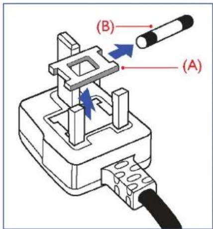
(A) (B)WARNING - THIS APPLIANCE MUST BE EARTHED. Important:
This apparatus is supplied with an approved moulded 13A plug. To change a fuse in this type of plug proceed as follows:
- Remove fuse cover and fuse.
- Fit new fuse which should be a BS 1362 5A,A.S.T.A. or BSI approved type.
- Refit the fuse cover.
If the fitted plug is not suitable for your socket outlets, it should be cut off and an appropriate 3-pin plug fitted in its place.
If the mains plug contains a fuse, this should have a value of 5A. If a plug without a fuse is used, the fuse at the distribution board should not be greater than 5A.
Note: The severed plug must be destroyed to avoid a possible shock hazard should it be inserted into a 13A socket elsewhere.

natural_image
Diagram of a fuse or socket with colored wires (green, blue, red) and connectors, no text or symbols present.How to connect a plug
The wires in the mains lead are coloured in accordance with the following code: BLUE - "NEUTRAL" ("N") BROWN - "LIVE" ("L") GREEN & YELLOW - "EARTH" ("E")
- The GREEN AND YELLOW wire must be connected to the terminal in the plug which is marked with the letter "E" or by the Earth symbol or coloured GREEN or GREEN AND YELLOW.
- The BLUE wire must be connected to the terminal which is marked with the letter "N" or coloured BLACK.
- The BROWN wire must be connected to the terminal which marked with the letter "L" or coloured RED.
Before replacing the plug cover, make certain that the cord grip is clamped over the sheath of the lead - not simply over the three wires.
END-OF-LIFE DISPOSAL
Your new TV/Monitor contains materials that can be recycled and reused. Specialized companies can recycle your product to increase the amount of reusable materials and to minimize the amount to be disposed of.
Please find out about the local regulations on how to dispose of your old monitor from your local dealer.
(For customers in Canada and U.S.A.)
This product may contain lead and/or mercury. Dispose of in accordance to local-state and federal regulations. For additional information on recycling contact www.eia.org (Consumer Education Initiative)
WASTE ELECTRICAL AND ELECTRONIE EQUIPMENT-WEEE
Attention users in European Union private households
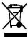
This marking on the product or on its packaging illustrates that, under European Directive 2002/96/EG governing used electrical and electronic appliances, this product may not be disposed of with normal household waste. You are responsible for disposal of this equipment through a designated waste electrical
and electronic equipment collection. To determine the locations for dropping off such waste electrical and electronic, contact your local government office, the waste disposal organization that serves your household or the store at which you purchased the product.
Attention users in United States:
Like all LCD products, this set contains a lamp with Mercury. Please dispose of according to all Local, State and Federal Laws. For the disposal or recycling information, contact: www.mygreenelectronics.com or www.eiae.org.

END OF LIFE DIRECTIVES-RECYCLING
Your new TV/Monitor contains several materials that can be recycled for new uses.
Like all LCD products, this set contains a lamp with Mercury, please dispose of according to all Local, State and Federal laws.
TABLE OF CONTENTS
1. UNPACKING AND INSTALLATION....7
1.1. UNPACKING 7
1.2. PACKAGE CONTENTS....7
1.3. INSTALLATION NOTES 7
1.4. PORTRAIT MOUNTING 8
1.5. INSTALLING AND REMOVING STANDS 9
1.5.1 How to install stands 9
1.5.2 How to remove the stands....9
2. PARTS AND FUNCTIONS ...... 10
2.1. FRONT VIEW 10
2.2. REAR VIEW 11
2.3. INPUT/OUTPUT TERMINALS 12
2.4. REMOTE CONTROL....14
2.4.1. GENERAL FUNCTIONS 14
2.4.2. INSERTING THE BATTERIES IN THE REMOTE CONTROL.... 16
2.4.3. OPERATING RANGE OF THE REMOTE CONTROL....16
3. CONNECTIONS TO EXTERNAL EQUIPMENT 17
3.1. USING THE CABLE RETAINER.... 17
3.2. CONNECTING EXTERNAL EQUIPMENT (DVD/VCR/VCD) 17
3.2.1. USING COMPONENT VIDEO INPUT 17
3.2.2. USING HDMI INPUT 17
3.3. CONNECTING A PC....18
3.3.1. USING VGA INPUT 18
3.3.2. USING DVI INPUT 18
3.3.3. USING HDMI INPUT 18
3.4. EXTERNAL AUDIO CONNECTION 19
3.4.1. CONNECTING EXTERNAL SPEAKERS.... 19
3.4.2. CONNECTING EXTERNAL AUDIO DEVICE 19
3.5. CONNECTING ANOTHER RX-55 MONITOR....20
4. OSD MENU 21
4.1. NAVIGATING THE OSD MENU 21
4.1.1. NAVIGATING THE OSD MENU USING THE REMOTE CONTROL 21
4.1.2. NAVIGATING THE OSD MENU USING THE MONITOR'S CONTROL BUTTONS......22
4.2. OSD Menu Overview 23
4.2.1. PICTURE MENU 23
4.2.2. SCREEN MENU....26
4.2.3. AUDIO MENU 28
4.2.4. PIP MENU 29
4.2.5. CONFIGURATION 1 MENU 30
4.2.6. CONFIGURATION 2 MENU 33
4.2.7. ADVANCED OPTION MENU 34
5. INPUT MODE 39
6. CLEANING AND TROUBLESHOOTING....41
6.1. CLEANING 41
6.2. TROUBLESHOOTING....42
7. TECHNICAL SPECIFICATIONS 43
1. UNPACKING AND INSTALLATION
1.1. UNPACKING
- This product is packed in a carton, together with the standard accessories.
- Any other optional accessories will be packed separately.
• After opening the carton, ensure that the content is in good condition and complete.
- The weight of the product differs - depending on the type. Due to the size and weight it is recommended to move it by 2 people.
1.2. PACKAGE CONTENTS
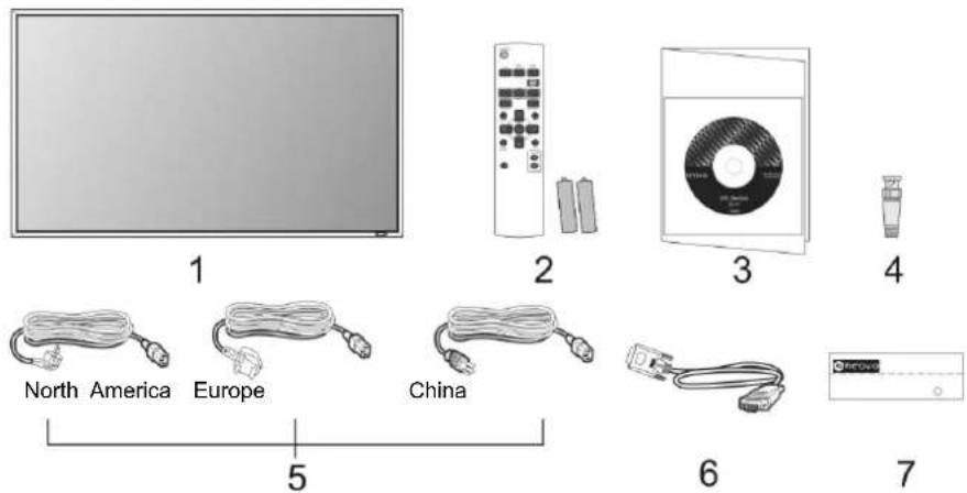
Please verify that you received the following items with your package content:
text_image
1 North America Europe China 2 3 4 5 6 7- LCD monitor
- Remote control with batteries
- CD, Quick guide
- BNC-to-RCA adapter (×5)
- Power cords
- VGA cable
-
LOGO plate
-
Please make sure that for all other regions, apply a power cord that conforms to the AC voltage of the power socket and has been approved by and complies with the safety regulations of the particular country.
- You might like to save the package box and packing material for shipping the monitor.
- Table stands are prepared as options.
1.3. INSTALLATION NOTES
- Due to the high power consumption, always use the plug exclusively designed for this product. If an extended line is required, please consult your service agent.
- The product should be installed on a flat surface to avoid tipping. The distance between the back of the product and the wall should be maintained for proper ventilation. Avoid installing the product in the kitchen, bathroom or any other places with high humidity so as not to shorten the service life of the electronic components.
- The product can normally operate only under 2500m in height. It might abnormally function at a place over 2500m in height and do not install and operate there.
1.4. PORTRAIT MOUNTING
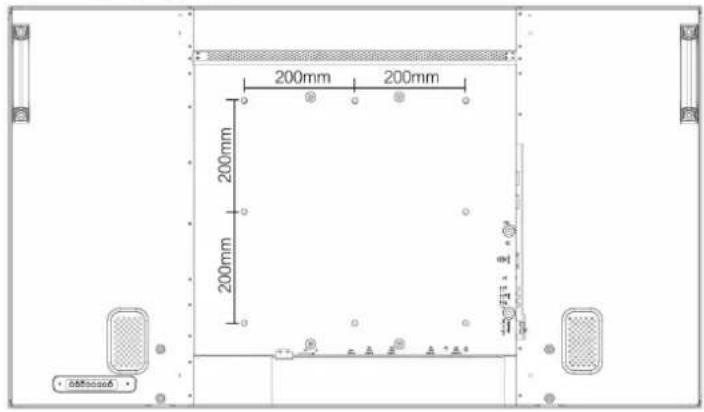
Wall mounting holes
text_image
200mm 200mm 200mm 200mm 200mm 200mm 200mm 200mm 200mm 200mm 200mm 200mm 200mm 200mm 200mm 200mm 200mm 200mm 200mm 200mm 200mmNotes:
- Metric 8 (12mm) screws are needed for wall mounting (not included).
- The mounting interface should comply with the UL1678 standard in North America. The mounting means should strong enough to bear the weight of the monitor (approx. 46.4 kg without stand).
How to set up the Portrait position
Set up the Portrait position by rotating your monitor to make the remote control sensor locate on the lower side. (Shown below)
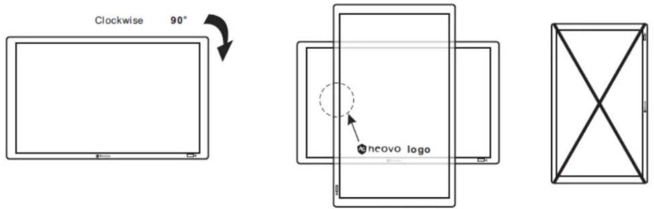
Cautions:
- "AC In" should always face down (on the bottom of the connector) to avoid current leaking problem
- Applying the monitor to portrait position may shorten the panel life time of the LCD backlight monitor
- Suggested operation environments for Portrait position:
Operation Condition
| Temperature 5 - 35°C / 41 – 95°F |
| Humidity 20 – 80% condensation |
1.5. INSTALLING AND REMOVING STANDS
1.5.1 How to install stands
- Please turn the monitor off.
- After inserting the stand in the guide block, tighten the screws on both sides of the monitor.
NOTE:
The stands are available as option. The longer end of the stand should face to the front while installing.
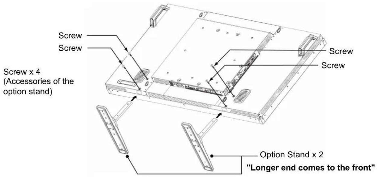
text_image
Screw Screw Screw x 4 (Accessories of the option stand) Screw Screw Option Stand x 2 "Longer end comes to the front"1.5.2 How to remove the stands
- Spread the protective sheet on a flat surface.
- Place the monitor face-down on a protective sheet.
- Remove screws using a screwdriver and place them in a safe place for reuse.
2. PARTS AND FUNCTIONS
2.1. FRONT VIEW
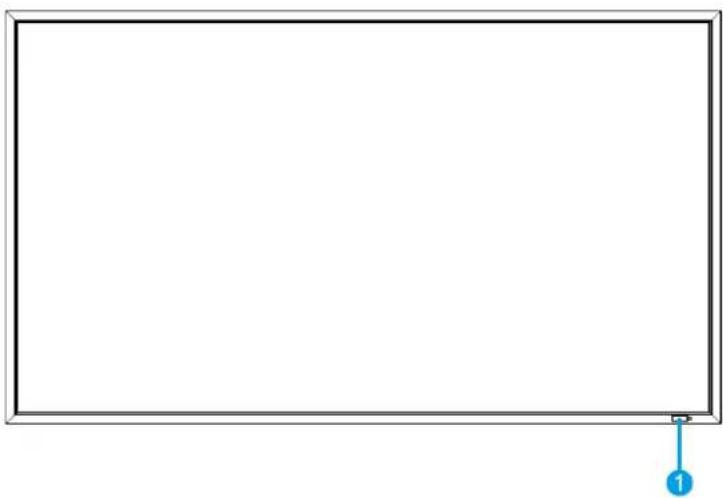
natural_image
Empty white rectangle with a blue arrow pointing to the corner (no text or symbols)1. Remote control sensor, ambient light sensor and power status indicator
- Receives command signals from the remote control.
- Detects the ambient lighting condition around the monitor and the image brightness will be auto adjusted when "LIGHT SENSOR" set to "ON" on OSD menu.
-
Indicates the operating status of the monitor:
-
lights green when the monitor is turned on
- lights red when the monitor is in standby mode
- lights amber when the monitor enters DPMS mode
- When SCHEDULE is enabled, it would blink green and red
- If the indicator blinks red, it tells that a failure is detected
- Off when the main power of the monitor is turned off
2.2. REAR VIEW
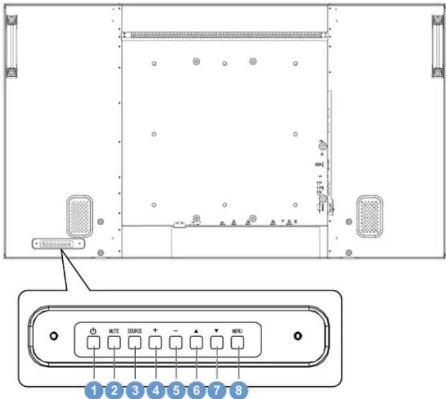
text_image
(Aerospace) 1 2 3 4 5 6 7 8 MUTE SOURCE - MENU1. POWER button(↓)(
To switch the power on or put the monitor to standby.
2. MUTE button
To switch the audio mute ON/OFF.
3. SOURCE button
To set the function while OSD menu is on or to activate input selection menu while OSD menu is off.
4. PLUS (+) button
To increase the adjustment while OSD menu is on, or to increase the audio output level while the OSD menu is off.
5. MINUS (-) button
To decrease the adjustment while OSD menu is on, or to decrease the audio output level while the OSD menu is off.
6. UP (▲) button
To move the highlight bar up to adjust the selected item while OSD menu is on.
7. DOWN (▼) button
To move the highlight bar down to adjust the selected item while OSD menu is on.
8. MENU button
To return to previous menu while OSD menu is on or to activate the OSD menu when the OSD menu is off.
Note: Keyboard Control Lock Mode This function completely disables the access to all Keyboard Control functions. To enable the keyboard control lock, press both of “▲” and “▼” buttons and hold down continuously for more than 3 seconds. To recover back to the user mode, press both of “▲” and “▼” and hold continuously for three 3 seconds.
2.3. INPUT/OUTPUT TERMINALS
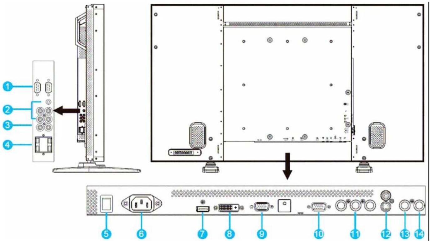
text_image
Diagram of a computer monitor rear panel with labeled ports and connectors, showing internal structure and component layout.1. RS232C (OUT/IN)
RS232C network connection input/output for the use of loop through function.
2. AUDIO IN (AUDIO1/AUDIO2/ AUDIO3)
Connect to the audio output of a computer or an AV device.
(a) Audio 1: ∅3.5 stereo mini-jack connector
(b) Audio 1: RCA connector
(c) Audio 1: RCA connector
3. AUDIO OUT R/L (RCA connector)
Outputs the audio signal from the AUDIO IN (AUDIO1/AUDIO2/AUDIO3) or HDMI jack.
4. EXTERNAL SPEAKER TERMINAL R/L
Outputs the audio signal from the AUDIO IN (AUDIO1/AUDIO2/AUDIO3) or HDMI jack to external speakers.
5. EcoSwitch (Main power switch)
Press to switch the main power on/off.
6. AC IN
Connect the supplied power cord to the wall outlet.
7. RGB1 IN (HDMI connector)
Connect to the HDMI output of an AV device or connect to the DVI-D output of a PC. (Using a DVI-HDMI cable)
8. RGB2 IN (DVI-D connector)
Connect to the DVI-D output of a PC or connect to the HDMI output of an AV device (Using a DVI-HDMI cable).
9. RGB3 IN (D-Sub connector)
Connect to the D-sub output of a computer.
10. RGB OUT (D-Sub connector)
Outputs the D-sub signal from the RGB3 IN jack.
11. DVD/HD IN (COMPONENT) (BNC connector x 3)
Component video input (YPbPr) for connecting to the component output of an AV device.
12. S-VIDEO IN
To input the S-video (Y/C separate signal).
*Remark: video signal can be only accepted by S-Video through either RCA connector or 4-Pin mini din connector
13. VIDEO IN (BNC connector)
To input a composite video signal. Note: that BNC and RCA are not available at the same time.
14. VIDEO OUT (BNC connector)
To output the composite video signal from VIDEO IN connector.
2.4. REMOTE CONTROL
2.4.1. GENERAL FUNCTIONS
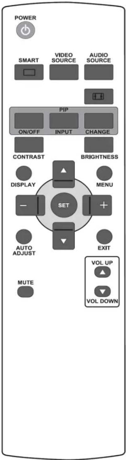
text_image
POWER SMART VIDEO SOURCE AUDIO SOURCE PIP ON/OFF INPUT CHANGE CONTRAST BRIGHTNESS DISPLAY MENU SET AUTO ADJUST EXIT MUTE VOL UP VOL DOWNPOWER

POWER button
Press to switch on the monitor from standby mode. Press again to turn it off to standby mode.
SMART

SMART button
To select picture mode from:
• STANDARD: for images (factory setting)
• HIGHBRIGHT: for moving image such as Video
• SOFT: to let the image softly
• sRGB: for text based images
VIDEO SOURCE

VIDEO SOURCE button
To activate the video source selection menu. Press it repeatedly to select the video input source from HDMI, DVI-D, VGA, YPbPr, S-VIDEO, and VIDEO.
AUDIO SOURCE

AUDIO SOURCE button
To activate the audio source selection menu. Press it repeatedly to select the video input source from HDMI, AUDIO1, AUDIO2, and AUDIO3.

Picture format button
To switch screen aspect ratio between
PC signal: FULL, NORMAL, CUSTOM, and REAL (OFF).
Video signal: FULL, NORMAL, DYNAMIC, CUSTOM, and REAL (OFF).
PIP (Picture In Picture) buttons

ON/OFF button: To turn PIP mode ON/OFF.

INPUT button: To select the input signal for the sub-picture.

CHANGE button: To exchange between the main picture and sub picture.

CONTRAST button
Press to open the CONTRAST OSD selection, and then press the PLUS or MINUS button to adjust the value.

BRIGHTNESS button
Press to open the BRIGHTNESS OSD selection, and then press the PLUS or MINUS button to adjust the value.
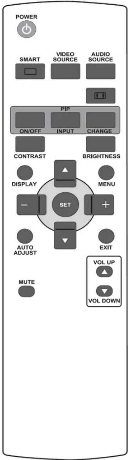
text_image
POWER SMART VIDEO SOURCE AUDIO SOURCE PIP ON/OFF INPUT CHANGE CONTRAST BRIGHTNESS DISPLAY MENU SET AUTO ADJUST EXIT MUTE VOL UP VOL DOWN
DISPLAY button
To turn on/off the information OSD displayed on the upper right corner of the screen.

MENU button
To turn the OSD menu on/off.

UP button
- To move the highlight bar up to adjust the selected item when OSD menu is on.
- To move the sub-picture up in "PIP" mode.

DOWN button
- To move the highlight bar down to adjust the selected item when OSD menu is on.
- To move the sub-picture down in "PIP" mode.

PLUS button
- To move the highlight bar right to the submenu when OSD menu is on.
- To increase the adjustment with OSD menu.
- To move the sub-picture right in "PIP" mode.

MINUS button
- To move the highlight bar left to the previous submenu or main menu when OSD menu is on.
- To decrease the adjustment with OSD menu.
- To move the sub-picture left in "PIP" mode.

SET button
To activate the setting with OSD menu.

\_AUTO ADJUST button
ADJUST Note: For the VGA input only. To execute the AUTO ADJUST function.

EXIT button
To turn to the previous OSD menu.
MUTE

MUTE button
To turn the mute function on/off.
VOL UP

VOL UP button
To increase the audio output level.

VOL DOWN button
To decrease the audio output level.
2.4.2. INSERTING THE BATTERIES IN THE REMOTE CONTROL

natural_image
Three-step diagram showing a remote control device with rotating buttons and battery symbols (no text or labels)The remote control is powered by 1.5V AAA batteries. To install or replace batteries:
- Press and slide to open the cover.
- Align the batteries according to the (+) and (−) indications inside the case.
- Replace the cover.
Caution:
Incorrect use of batteries can result in leaks or bursting. Be careful especially about the following points.
- Place "AAA" batteries matching the + and - signs on each battery to the + and - signs of the battery compartment.
- Do not mix battery types.
- Do not combine new batteries with used ones. It causes shorter battery life or leakage of batteries.
- Remove dead batteries immediately to prevent battery liquid from leaking into the battery compartment. Don't touch exposed battery acid, it cause damage to your skin.
Note:
If you do not intend to use the Remote Control for a long period, remove the batteries.
2.4.3. OPERATING RANGE OF THE REMOTE CONTROL
Point the top of the remote control toward the monitor's remote control sensor when pressing a button. Use the remote control within a distance of about 10m/33ft from the monitor's remote control sensor and within a horizontal and vertical angle of 30 degrees.
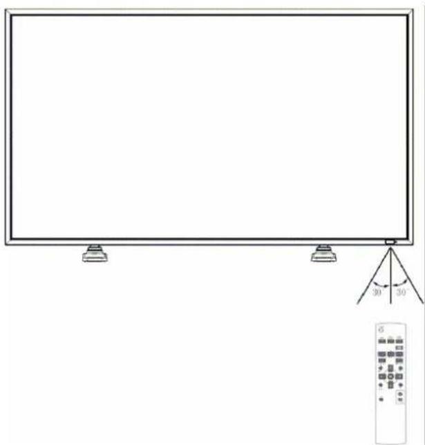
natural_image
Simple line drawing of a blank rectangular frame with three small supports and a small remote control panel below (no text or symbols)Note: The remote control may not function properly when the remote control sensor on the monitor is under direct sunlight or strong illumination, or when there is an obstacle in the path of signal transmission.
3. CONNECTIONS TO EXTERNAL EQUIPMENT
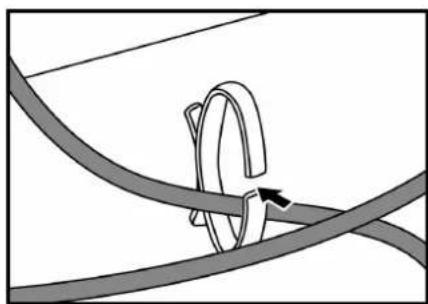
3.1. USING THE CABLE RETAINER
natural_image
Diagram showing a rope knot with a curved wire and directional arrow (no text or symbols)3.2. CONNECTING EXTERNAL EQUIPMENT (DVD/VCR/VCD)
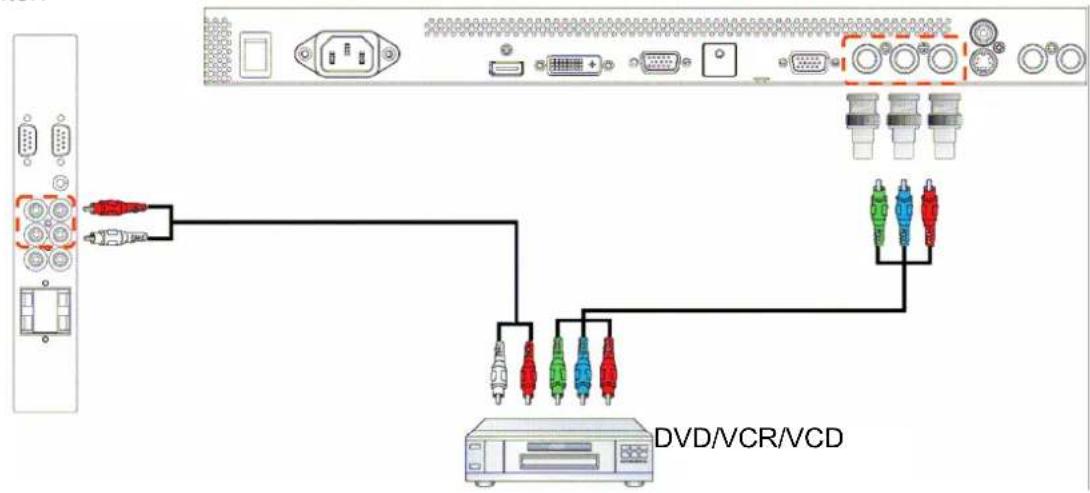
3.2.1. USING COMPONENT VIDEO INPUT
- Connect the green-colored (labeled as "Y") jack of the device to the green-colored "Y" jack of the monitor.
- Connect the blue-colored (labeled as "Pb") jack of the device to the blue-colored "Pb" jack of the monitor.
- Connect the red-colored (labeled as "Pr") jack of the device to the red-colored "Pr" jack of the monitor.
- Connect the red (R) and white (L) audio jacks of the device to the AUDIO IN (AUDIO2 or AUDIO3) jacks of the monitor.
text_image
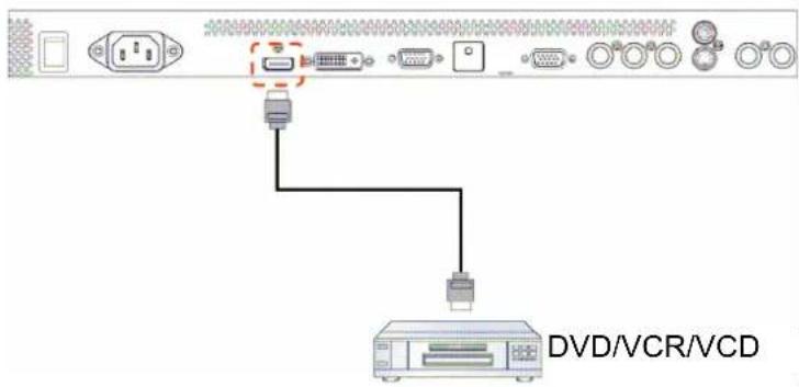
DVD/VCR/VCD3.2.2. USING HDMI INPUT
Connect the HDMI connector of the external device to the HDMI input of the monitor.
text_image
DVD/VCR/VCD3.3. CONNECTING A PC
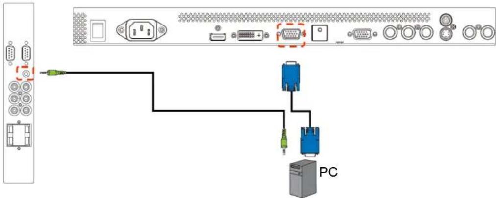
3.3.1. USING VGA INPUT
- Connect the 15-pin VGA connector of the PC to the VGA IN connector of the monitor.
- Connect the audio cable to the AUDIO IN (AUDIO1) input of the monitor.
text_image
Diagram showing connection between a computer terminal and an electronic device via USB cable, with labeled ports and connectors.3.3.2. USING DVI INPUT
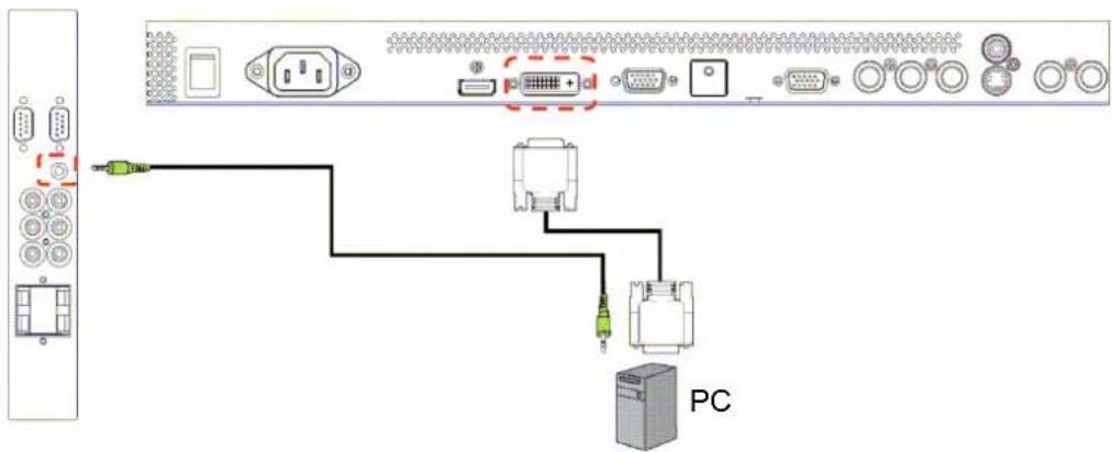
- Connect the DVI-D connector of the PC to the DVI-D connector of the monitor.
- Connect the audio cable to the AUDIO IN (AUDIO1) input of the monitor.
text_image
Diagram showing connection between a device labeled 'PC' via cable and connectors, with visible ports and wiring details.3.3.3. USING HDMI INPUT
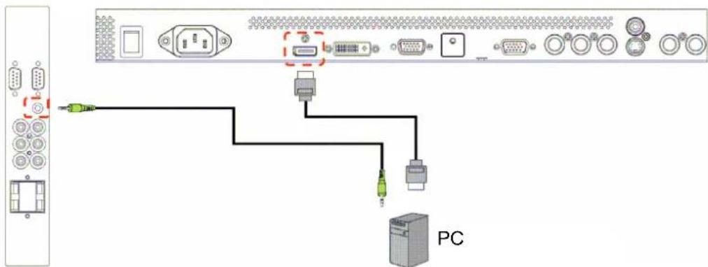
- Connect the DVI-D connector of the PC to the HDMI connector of the monitor.
- Connect the audio cable to the AUDIO IN (AUDIO1) input of the monitor.
text_image
Diagram showing connection between a device with labeled ports and connectors, including a PC terminal.3.4. EXTERNAL AUDIO CONNECTION
3.4.1. CONNECTING EXTERNAL SPEAKERS
-
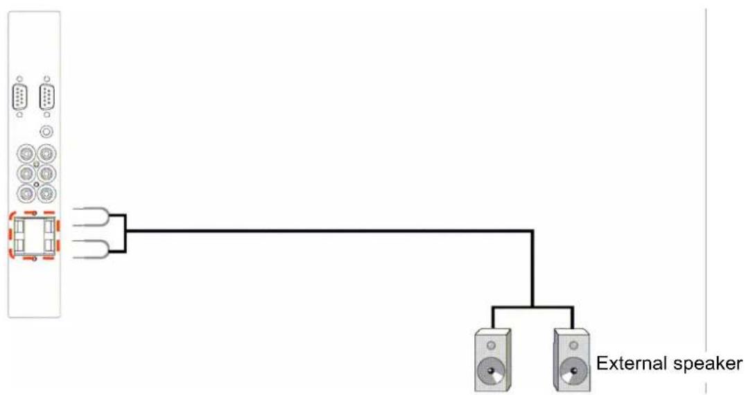
Connect the speaker wires to the external speaker (SPEAKERS) output of the monitor.
-
Turn on the monitor.
Note: Before connecting the speaker wires to the monitor, turn off your monitor.
text_image
External speaker3.4.2. CONNECTING EXTERNAL AUDIO DEVICE
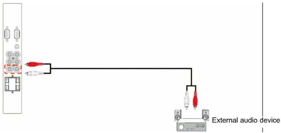
Connect the red (R) and white (L) audio jacks of the external audio device to the AUDIO OUT R/L jacks of the monitor.
text_image
External audio device3.5. CONNECTING ANOTHER RX-55 MONITOR
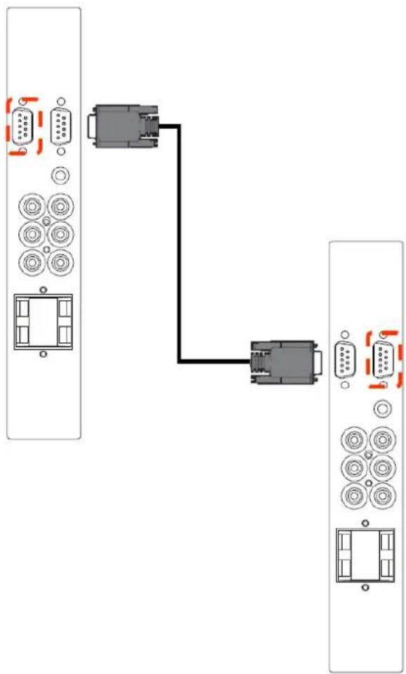
You can interconnect multiple RX-55 monitors to create a daisy-chain configuration for applications like a TV wall.
- Connect the VGA OUT connector of the monitor to the VGA IN connector of another RX-55 monitor.
- Connect the RS232C OUT connector of the monitor to the RS232C IN connector of another RX-55 monitor.
flowchart
graph TD
    A["Server Rack 1"] --> B["Switch"]
    C["Server Rack 2"] --> B
    B --> D["Port 1"]
    B --> E["Port 2"]
    D --> F["Port 3"]
    E --> G["Port 4"]
    style A fill:#f9f,stroke:#333
    style C fill:#f9f,stroke:#333
    style B fill:#ccf,stroke:#333
    style D fill:#ccf,stroke:#333
    style E fill:#ccf,stroke:#333
Note: For better image performance, it is recommended that the tiling number does not exceed 3x3 max.displays to be used in a daisy-chain configuration.
4. OSD MENU
An overall view of the On-Screen Display (OSD) structure is shown below. You can use it as a reference for further adjusting your monitor.
4.1. NAVIGATING THE OSD MENU
4.1.1. NAVIGATING THE OSD MENU USING THE REMOTE CONTROL
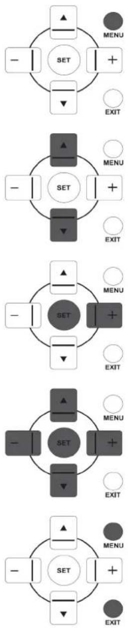
-
Press the MENU button on the remote control to display the OSD menu.
-
Press the UP/DOWN button to choose the item you want to adjust.
-
Press the PLUS/SET button to enter the submenu.
-
In the submenu, press the UP/DOWN button to toggle between items, or press PLUS/MINUS button to adjust settings. If there is a submenu, press the SET button to enter the submenu.
-
Press the EXIT button on the remote control to return to the previous menu, or press the MENU button to exit the OSD menu.
4.1.2. NAVIGATING THE OSD MENU USING THE MONITOR'S CONTROL BUTTONS
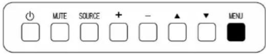
text_image
MUTE SOURCE + - ▲ MENU- Press the MENU button to display the OSD menu.
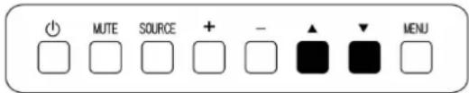
text_image
MUTE SOURCE + - ▲ ▼ MENU- Press the ▲/▼ button to choose the item you want to adjust.
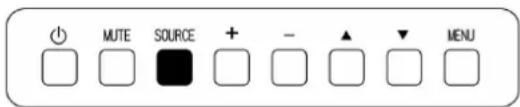
text_image
MUTE SOURCE + - ▲ ▼ MENU- Press the SOURCE button to enter the submenu.
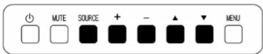
text_image
Power MUTE SOURCE + - ▲ ▼ MENU- In the submenu, press the ▲/▼ button to toggle between items, or press PLUS/MINUS button to adjust settings. If there is a submenu, press the SOURCE button to enter the submenu.
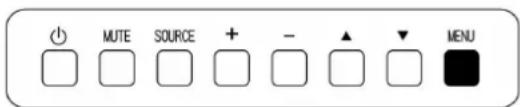
text_image
MUTE SOURCE + - ▲ ▼ MENU- Press the MENU button to return to the previous menu, or press the MENU button several times to exit the OSD menu.
4.2. OSD Menu Overview
4.2.1. PICTURE MENU
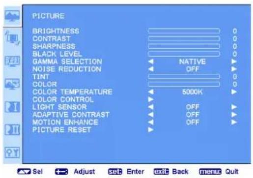
text_image
PICTURE BRIGHTNESS CONTRAST SHARPNESS BLACK LEVEL GAMMA SELECTION NATIVE NOISE REDUCTION OFF TINT 0 COLOR 0 COLOR TEMPERATURE 5000K COLOR CONTROL LIGHT SENSOR OFF ADAPTIVE CONTRAST OFF MOTION ENHANCE OFF PICTURE RESET Sel Adjust set Enter exit Back menu QuitBRIGHTNESS
Adjust the overall image brightness by changing the intensity of the LCD panel's backlight.
Press the PLUS/MINUS button to adjust.
CONTRAST
Adjust to sharpen the picture quality. The black portions of the picture become richer in darkness and the white become brighter.
Press the PLUS/MINUS button to adjust.
SHARPNESS
Adjust to improve detail.
Press the PLUS/MINUS button to adjust.
BLACK LEVEL
Adjust to change the image brightness.
Press the PLUS/MINUS button to adjust.
GAMMA SELECTION
Select a display gamma value to best suit the image and optimize image brightness and contrast.
Press the PLUS/MINUS button to toggle between
- Native • 2.2
• 2.4 • S GAMMA
NOISE REDUCTION
Adjust to remove the noise in the image. You can select a suitable noise reduction level.
Press the PLUS/MINUS button to toggle between
- OFF - LOW
- MIDDLE - HIGH
TINT
Note: For HDMI-Video timing, DVI-D (HD timing), DP (HD timing), YPbPr, S-VIDEO, and VIDEO (AV) inputs only.
Adjust to change the color tint of the image.
Press the PLUS/MINUS button to adjust. Press the PLUS button and the tone color becomes greenish.
Press the MINUS button and the tone color becomes purplish.
COLOR
Note: For HDMI-Video timing, DVI-D (HD timing), DP (HD timing), YPbPr, S-VIDEO, and VIDEO (AV) inputs only.
Adjusts to increase or decrease the intensity of colors in the image.
Press the PLUS/MINUS button to adjust. Press the PLUS button to increase color intensity, or press the MINUS button to decrease color intensity.
COLOR TEMPERATURE
Select a color temperature for the image. The image looks reddish with a lower color temperature, and looks bluish with a higher color temperature.
Press the PLUS/MINUS button to toggle between
• 5000K • 6500K
• 7500K • 9300K
• 10000K • NATIVE
- USER
COLOR CONTROL
Note: This function is only available when COLOR TEMPERATURE is set to User.
With this function you can adjust the color tones of the image precisely by changing the RED, GREEN, and BLUE settings independently.
Press the SET/PLUS button to open the submenu. Press the UP/DOWN button to select RED, GREEN or BLUE, and press the PLUS/MINUS button to adjust.
LIGHT SENSOR
This is the EcoSmart Sensor, which can auto adjust brightness for ultra low power consumption.
Choose to enable or disable the light sensor. Once enabled, the image brightness will be adjusted automatically when ambient lighting condition changes.
Press the PLUS/MINUS button to make selection.
ADAPTIVE CONTRAST
When there is a need to display dark image, the Adaptive Contrast capability is to help optimize automatically the contract ratio of the LCD panel in dark scenes as well as to deliver smoother and more realistic gradients.
When turned on, this function helps enhance image contrast when displaying dark scenes.
Press the PLUS/MINUS button to make selection.
MOTION ENHANCE
By adopting 120Hz premium-grade panel, RX-55 is built-in with MotionEnhance technology to reduce the motion blur (by slipping in a new frame between each of the original frames to double the refresh rate).
Press the PLUS/MINUS button to make selection.
PICTURE RESET
Reset all settings in the PICTURE menu.
Press the SET/PLUS button to open the submenu, and then press the UP/DOWN button to make selection. Select Reset and press the SET button to restore settings to factory preset values. Press the EXIT button to cancel and then return to the previous menu.
4.2.2. SCREEN MENU
text_image
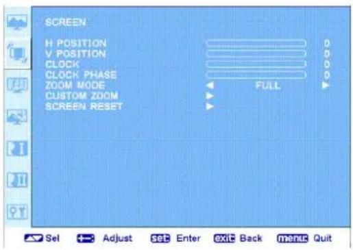
SCREEN H POSITION V POSITION CLOCK CLOCK PHASE ZOOM MODE CUSTOM ZOOM SCREEN RESET 0 0 0 0 FULL Sel Adjust set Enter Exit Back menu QuitH POSITION
Adjust the horizontal placement of the picture.
Press the PLUS button to move the image to the right, or press the MINUS button to move the image to the left.
V POSITION
Adjust the vertical placement of the picture.
Press the PLUS button to move the image up, or press the MINUS button to move the image down.
CLOCK
Note: For the VGA input only.
Adjust the width of the image.
Press the PLUS button to expand the width of the image, or press the MINUS button to shrink the width of the image.
CLOCK PHASE
Note: For the VGA input only.
Adjust to improve the focus, clarity and stability of the image.
Press the PLUS/MINUS button to adjust.
ZOOM MODE
The pictures you receive may be transmitted in 16:9 format (widescreen) or 4:3 format (conventional screen). 16:9 pictures sometimes have a black band at the top and bottom of the screen (letterbox format).
This function allows you to optimize the picture display on screen. The following zoom modes are available for
PC mode: FULL, NORMAL, CUSTOM, and REAL (OFF).
Video mode: FULL, NORMAL, DYNAMIC, CUSTOM, and REAL (OFF).
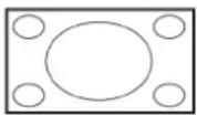
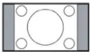
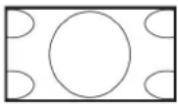
- FULL - This mode restores the correct proportions of pictures transmitted in 16:9 using the full screen display.
- NORMAL - The picture is reproduced in 4:3 formats and a black band is displayed on either side of the picture.
- DYNAMIC - Fill the entire screen by stretching 4:3 pictures non-proportionally.
- CSUTOM - Choose to apply the custom zoom settings in the CUSTOM ZOOM submenu.
- REAL (OFF) - This mode displays the image pixel-by-pixel on screen without scaling the original image size.
CUSTOM ZOOM
Note: This item is only available when the ZOOM MODE setting is set to CUSTOM.
You can use this function to further customize the zoom settings to suit the image you want to display. Press the SET/PLUS button to open the submenu. Use the UP/DOWN button to toggle between the following items, and use the PLUS/MINUS button to adjust.
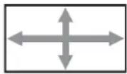
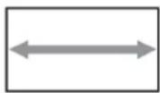
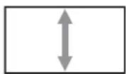
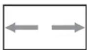
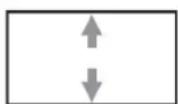
- ZOOM - Expands the horizontal and vertical sizes of the image simultaneously.
- HZOOM - Expands the horizontal size of the image only.
- VZOOM - Expands the vertical size of the image only.
- HPOSI - Moves the horizontal position of the image left or right.
- VPOSI - Moves the vertical position of the image up or down.
SCREEN RESET
Reset all settings in the SCREEN menu.
Press the SET/PLUS button to open the submenu, and then press the UP/DOWN button to make selection. Select Reset and press the SET button to restore settings to factory preset values. Press the EXIT button to cancel and then return to the previous menu.
4.2.3. AUDIO MENU
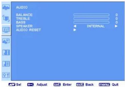
text_image
AUDIO BALANCE 0 TREBLE 0 BASS 0 SPEAKER INTERNAL AUDIO RESET Sel Adjust set Enter exit Back menu QuitBALANCE
Adjust to emphasize left or right audio output balance. Press the PLUS/MINUS button to adjust.
TREBLE
Adjust to increase or decrease higher-pitched sounds. Press the PLUS/MINUS button to adjust.
BASS
Adjust to increase or decrease lower-pitched sounds. Press the PLUS/MINUS button to adjust.
SPEAKER
Set the monitor to play audio using the built-in (internal) speaker or external speakers. Use the PLUS/MINUS button to toggle between
• INTERNAL • EXTERNAL
AUDIO RESET
Reset all settings in the AUDIO menu.
Press the SET/PLUS button to open the submenu, and then press the UP/DOWN button to make selection. Select Reset and press the SET button to restore settings to factory preset values. Press the EXIT button to cancel and then return to the previous menu.
4.2.4. PIP MENU
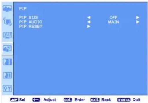
text_image
PIP PIP SIZE OFF PIP AUDIO MAIN PIP RESET Sel Adjust set Enter exit Back menu QuitPIP SIZE
Select the size of the sub picture in the PIP (Picture-in-Picture) mode.
Press the PLUS/MINUS button to toggle between
- SMALL - MIDDLE
• LARGE
PIP AUDIO
Select the audio source in the PIP (Picture-in-Picture) mode.
Press the PLUS/MINUS button to toggle between
- MAIN - Select audio from the main picture
- SUB - Select audio from the sub picture.
PIP RESET
Reset all settings in the PIP menu.
Press the SET/PLUS button to open the submenu, and then press the UP/DOWN button to make selection. Select Reset and press the SET button to restore settings to factory preset values. Press the EXIT button to cancel and then return to the previous menu.
Notes:
- The PIP function is only available under certain signal source combinations as shown in the table below.
| Main picture signal source | |||||||
| VIDEO | S-VIDEO | YPbPr | VGA | DVI-D | HDMI | ||
| Sub picture signal source | VIDEO | × | × | × | × | × | × |
| S-VIDEO | × | × | × | × | × | × | |
| YPbPr | × × | × × | ○ | ○ | |||
| VGA | × | × | × | × | ○ ○ | ||
| DVI-D | × × | ○ | ○ | × × | |||
| HDMI | × | × | ○ ○ | × | × | ||
(○: PIP function available, ×: PIP function unavailable)
- The availability of the PIP function will also depend on the resolution of the input signal being used.
Note: For the VGA input only.
Use this function to let the monitor automatically optimize the display of VGA input image.
Press the SET button to adjust.
POWER SAVE
Set the monitor to reduce the power automatically.
Press the SET/PLUS button to open the submenu, and then press the UP/DOWN button to toggle between
- RGB - Select ON to let the monitor enter DPMS mode when no signal can be detected from the HDMI, DVI-D, and VGA inputs after three successive cycles. Use the PLUS/MINUS button to make selection.
- VIDEO - Select ON to let the monitor enter power saving mode when no signal is detected from the VIDEO, S-VIDEO and YPbPr inputs after three successive cycles. Use the PLUS/MINUS button to make selection.
LANGUAGE
Select the language for the OSD menu.
Press the PLUS/MINUS button to toggle between
To reduce image persistence and maximize the panel life in demanding surveillance or signage applications running 24/7, this product is equipped with three screen-saving functions.
Choose to enable the SCREEN SAVING function. Press the SET/PLUS button to open the submenu, and then press the UP/DOWN button to toggle among the following functions:
- COOLING FAN - Select on and the cooling fan is turning all the time. Select AUTO and the cooling fan will turn on when the system is needed.
- BRIGHTNESS - Select On and the brightness of the image will be reduced to an appropriate level, and the BRIGHTNESS setting in the PICTURE menu will become unavailable. Use the PLUS/MINUS button to make selection.
• ANTI-BURN-IN
Anti-Burn-in™ technology is useful in preventing image retention on the LCD display.
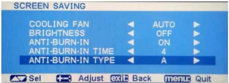
text_image
SCREEN SAVING COOLING FAN BRIGHTNESS ANTI-BURN-IN ANTI-BURN-IN TIME ANTI-BURN-IN TYPE AUTO OFF ON 4 A Sel +:- Adjust exit: Back menu: Quit| Item Function Value | ||
| ANTI-BURN-IN | Enables or disables Anti-Burn-In function. | ON (default)OFF |
| ANTI-BURN-INTIME | Sets the interval time (hour) between activating the Anti-Burn-In function. | 4 (default)4、5、6、8 |
| ANTI-BURN-INTYPE | Selects the Anti-Burn-In mode.TYPE A - Executes fastTYPE B - Slower but more precise than Type Frame.TYPE C - Slowest but the most precise anti-burn-in mode. | ABC (default) |
COLOR SYSTEM
Note: For the S-VIDEO and VIDEO (AV) input only.
Select the color system depending on the input video format.
Press the PLUS/MINUS button to toggle between
- AUTO
- NTSC
- PAL
- SECAM
• 4.43NTSC • PAL-60
CONFIGURATION RESET
Reset all settings in the Configuration 1 menu.
Press the SET/PLUS button to open the submenu, and then press the UP/DOWN button to make selection. Select Reset and press the SET button to restore settings to factory preset values. Press the EXIT button to cancel and then return to the previous menu.
FACTORY RESET
Reset all settings in the PICTURE, SCREEN, AUDIO, PIP, CONFIGURATION 1, CONFIGURATION 2, and ADVANCED OPTION menus. Press the SET/PLUS button to open the submenu, and then press the UP/DOWN button to make selection. Select YES and press the SET button to restore settings to factory preset values. Press the EXIT button to cancel and then return to the previous menu.
4.2.6. CONFIGURATION 2 MENU
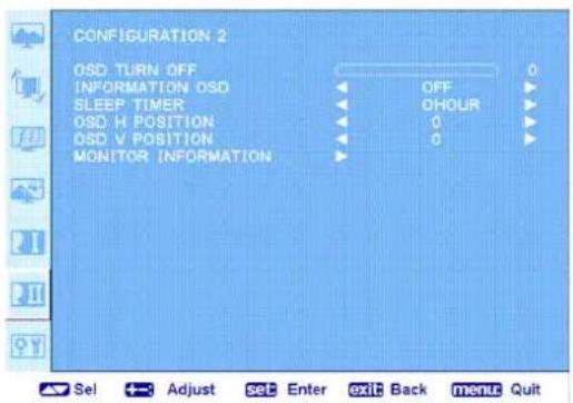
text_image
CONFIGURATION 2 OSD TURN OFF INFORMATION OSD SLEEP TIMER OSD H POSITION OSD V POSITION MONITOR INFORMATIONOSD TURN OFF
Set the period of time the OSD menu stays on the screen. (from 5 to 120 seconds) Press the PLUS/MINUS button to adjust.
INFORMATION OSD
Set the period of time the information OSD displayed on the upper right corner of the screen. (OFF, 1 to 10 seconds). The information OSD will display when input signal is changed.
Press the PLUS/MINUS button to adjust. The information OSD will remain on the screen when OFF is selected.
SLEEP TIMER
Set the monitor to turn itself off to standby mode within an amount of time you specify. (OFF, 1-24 hours from current time)
Press the PLUS/MINUS button to adjust.
Note: When the SLEEP TIMER is activated, the SCHEDULE settings will be disabled.
OSD H-POSITION
Adjust the horizontal position of the OSD menu.
Press the PLUS/MINUS button to adjust.
OSD V-POSITION
Adjust the vertical position of the OSD menu.
Press the PLUS/MINUS button to adjust.
MONITOR INFORMATION
Displays the information about your monitor, including model name, serial number, operating hours and software version.
Press the SET button to view the information. Press the EXIT button to return to the previous menu.
4.2.7. ADVANCED OPTION MENU
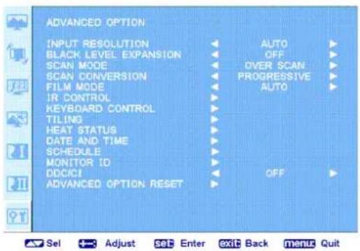
text_image
ADVANCED OPTION INPUT RESOLUTION BLACK LEVEL EXPANSION SCAN MODE SCAN CONVERSION FILM MODE IR CONTROL KEYBOARD CONTROL TILING HEAT STATUS DATE AND TIME SCHEDULE MONITOR ID DDCICI ADVANCED OPTION RESET AUTO OFF OVER SCAN PROGRESSIVE AUTO OFF Sel Adjust set Enter exit Back menu QuitINPUT RESOLUTION
Note: For the VGA input only.
Set the resolution of the VGA input. This is only required when the monitor is unable to detect the VGA input resolution correctly.
Press the PLUS/MINUS button to toggle between
• 1024x768, 1280x768, and 1360x768
- 640x480, 720x480, and 852x480
• 800x600, 1064x600, and 720x576
- 720x400 and 640x400
Auto: Determines the resolution automatically.
The setting you select becomes effective when POWER is turned OFF and ON again.
Select a suitable black level expansion setting to reveal more details in the dark parts of an image.
Press the PLUS/MINUS button to toggle between
- OFF - LOW
- MIDDLE
- HIGH
SCAN MODE
Note: For HDMI-Video timing, DVI-D (HD timing), DP (HD timing), Yapp, S-VIDEO, and VIDEO (AV) inputs only.
Change the display area of the image.
Press the PLUS/MINUS button to toggle between
• OVER SCAN - Display about 95% of the original size of the image. The rest of the areas surrounding the image will be cut off.
- UNDER SCAN - Display the image in its original size.
SCAN CONVERSION
Choose to enable or disable the IP (Interlace to Progressive) conversion function.
Press the PLUS/MINUS button to toggle between
- PROGRESSIVE - Enable the IP conversion function (recommended). Once enabled, the interlace input signal will be converted to progressive format for better display quality.
- INTERLACE: Disable the IP function. This mode is suitable for displaying motion pictures, but it increases the chance of image retention.
FILM MODE
Choose to turn on or off the film mode frame conversion function.
Press the PLUS/MINUS button to toggle between
- AUTO - Enable the film mode frame conversion function for movies and motion pictures. The monitor converts a 24 frames-per-second (24 fps) input signal format to DVD video signal format. Once this function is enabled, it is recommended that you set the SCAN CONVERSION function to PPRGRESSIVE.
- OFF - Disable the film mode frame conversion function. This mode is suitable for TV broadcasting and VCR signals.
IR CONTROL
Select the operation mode of the remote control when multiple RX-55 monitors are connected via the RS232C connection.
Press the SET/PLUS button to open the submenu, and then press the UP/DOWN button to toggle between
- NORAML - All monitors can be operated normally by the remote control.
- PRIMARY - Designate this monitor as the primary monitor for remote control operation. Only this monitor can be operated by the remote control.
- SECONDARY - Designate this monitor as the secondary monitor. This monitor cannot be operated by the remote control, and will only receive the control signal from the primary monitor via the RS232C connection.
- LOCK - Lock the remote control function of this monitor. To unlock, press and hold the DISPLAY button on the remote control for 5 seconds.
KEYBOARD CONTROL
Choose to enable or disable the function of the keyboard (control buttons) on the monitor.
Press the SET/PLUS button to open the submenu, and then press the UP/DOWN button to toggle between
- LOCK - Disable the keyboard.
- UNLOCK - Enable the keyboard.
TILING
With this function you can create a single large screen matrix (display wall) that consists of up to 25 RX-55 monitors (5 monitors each on the vertical and horizontal sides). This requires you to connect each RX-55 monitor in a daisy-chain configuration.
Example:
2 x 2 screen matrix (4 monitors)
H MONITORS = 2
V MONITORS = 2
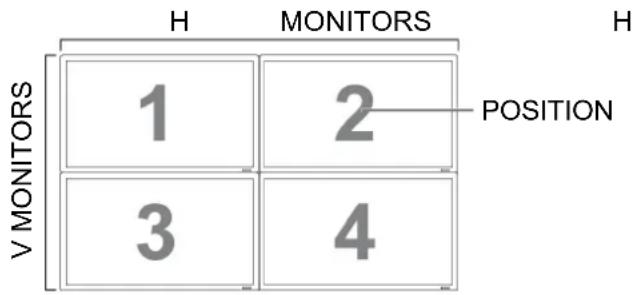
text_image
H MONITORS H 1 2 POSITION 3 4 V MONITORS5 x 5 screen matrix (25 monitors)
H MONITORS = 5
V MONITORS = 5
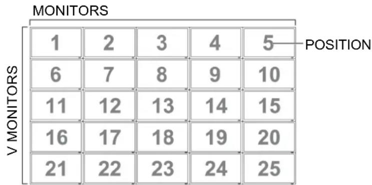
heatmap
| V MONITORS | 1 | 2 | 3 | 4 | 5 | |---|---|---|---|---|---| | 1 | 1 | 2 | 3 | 4 | POSITION | | 6 | 6 | 7 | 8 | 9 | 10 | | 11 | 11 | 12 | 13 | 14 | 15 | | 16 | 16 | 17 | 18 | 19 | 20 | | 21 | 21 | 22 | 23 | 24 | 25 |- H MONITORS - Select the number of monitors on the horizontal side.
- V MONITORS - Select the number of monitors on the vertical side.
- POSITION - Select the position of this monitor in the screen matrix.
- TILT COMP - Choose to turn on or off the frame compensation function. If turned on, the monitor will adjust the image to compensate for the width of the monitor bezels in order to accurately display the image.
- ENABLE: Choose to enable or disable the TILING function. If enabled, the monitor will apply the settings in H MONITORS, V MONITORS, POSITION, and TILT COMP.
Note: The PIP function will be disabled when the TILING function is enabled, and vice versa.
HEAT STATUS
This function allows you to check the thermal status of the monitor at any time. The accuracy of the temperature indicated is ±5 degrees.
Press the SET button to view the information of COOLING FAN1, COOLING FAN2, SENSOR 1, and SENSOR 2. Press the EXIT button to return to the previous menu.
DATE AND TIME
Adjust current date and time for the monitor's internal clock.
Press the PLUS button to open the submenu. Press the UP/DOWN button to toggle between the YEAR, MONTH, DAY, HOUR, MINUTE, and DAYLIGHT SAVING settings. Press the PLUS/MINUS button to adjust all settings except DAYLIGHT SAVING TIME Press the SET button to open the DAYLIGHT SAVING submenu. Press PLUS/MINUS button to make a selection and then press UP/DOWN button to adjust.
SCHEDULE
Note: You should set up current date and time in Date and time before using this function.
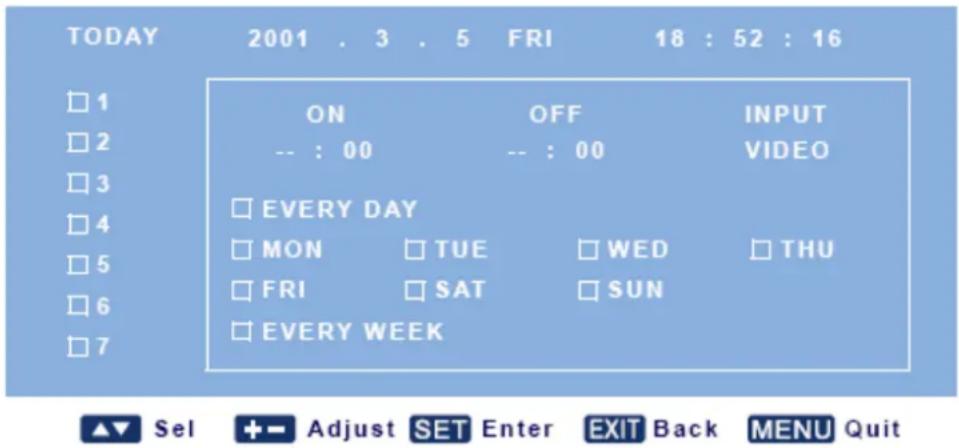
This function allows you to program up to seven different scheduled time intervals for the monitor. You can select the time the monitor turns on and turns off, the days in a week the monitor is activated, and which input source the monitor will use for each scheduled activation period.
- Press the SET button to open the submenu.
SCHEDULE
text_image
TODAY 2001 . 3 . 5 FRI 18 : 52 : 16 □1 ON OFF INPUT □2 -- : 00 -- : 00 VIDEO □3 □4 □ EVERY DAY □5 □ MON □ TUE □ WED □ THU □6 □ FRI □ SAT □ SUN □7 □ EVERY WEEK- Press the UP/DOWN button to select a schedule item (item 1 through item 7), and then press the PLUS button.
- With the ON item highlighted, press the UP/DOWN button to set the hour when the monitor will be turned on, then press the PLUS button to move to the minute slot to set the minute. If you do not want to use a power on time, select "_" for the hour slot and minute slot.
- Press the PLUS button to highlight the OFF item. Press the UP/DOWN button to set the hour when the monitor will be turned off, then press the PLUS button to move to the minute slot to set the minute. If you do not want to use a power off time, select "_" for the hourslot and minute slot.
- Press the PLUS button to highlight the Input item, and then press the UP/DOWN button to select an input source. If no input source is selected, the input source will remain the same as last selected.
- Press the PLUS button to select what days in a week this schedule item will be take effect, and then press the SET button.
- If you want to set up more schedule items, press the EXIT button and then repeat the steps above. A check mark in the box next to the number of the schedule item indicates that the selected schedule is in effect.
Notes:
- The selection of every day within a schedule item takes priority over other schedules that are set up to operate weekly.
- When schedule items overlap, scheduled power on time has priority over scheduled power off time.
- If there are two schedule items programmed for the same time, then the highest numbered schedule has priority.
MONITOR ID
Set the ID number for controlling the monitor via the RS232C connection. Each monitor must have an unique ID number when multiple RX-55 monitors are connected.
Press the SET/PLUS button to open the submenu, and then press the UP/DOWN button to select a monitor ID.
DDC/CI
Choose to turn ON or OFF the DDC/CI communication function. Select ON for normal use.
Press the PLUS/MINUS button to make selection.
ADVANCED OPTION RESET
Reset all settings in the ADVANCED OPTION menu.
Press the SET/PLUS button to open the submenu, and then press the UP/DOWN button to make selection. Select Reset and press the SET button to restore settings to factory preset values. Press the EXIT button to cancel and then return to the previous menu.
5. INPUT MODE
VGA Resolution
| Standard Resolution | Active Resolution | Refresh Rate | Pixel Rate | Aspect Ratio | Stand for Mode | |
| H Pixels V | Lines | |||||
| VGA | 640 | 480 | 60 Hz 25.175 MHz | 4:3 | Video Graphic | |
| 72 Hz | 72 Hz 31.5 MHz | |||||
| 75 Hz | 75 Hz 31.5 MHz | |||||
| WVGA | 720 | 400 | 70 Hz | 38.75 MHz Array | Wide Video Graphic 16:9 | |
| SVGA | 800 | 600 | 60 Hz 40 MHz | 4:3 | Super VGA | |
| 75 Hz | 75 Hz 49.5 MHz | |||||
| XGA | 1024 | 768 | 60 Hz 65 MHz | 4:3 | Extended Graphic Array | |
| 75 Hz | 75 Hz | 78.75 MHz | ||||
| WXGA | 1280 | 768 | 60 Hz | 79.5 MHz | 5:3 | Wide XGA |
| WXGA | 1280 | 800 | 60 Hz | 79.5 MHz | 16:10 | Wide XGA |
| SXGA | 1280 | 960 | 60 Hz | 108 MHz | 4:3 | Super XGA |
| SXGA | 1280 | 1024 | 60 Hz | 108 MHz | 5:4 | Super XGA |
| WXGA | 1360 | 768 | 60 Hz | 85.5 MHz | 16:9 | Wide XGA |
| WXGA | 1366 | 768 | 60 Hz | 85.5 MHz | 16:9 | Wide XGA |
| UXGA | 1600 | 1200 | 60 Hz | 162 MHz | 4:3 | Ultra XGA |
| HD1080 | 1920 | 1080 | 60 Hz | 148.5 MHz | 16:9 | HD1080 |
SDTV Resolution
| Standard Resolution | Active Resolution | Refresh Rate | Pixel Rate | Aspect Ratio | Stand for Mode | |
| H Pixels V | Lines | |||||
| 480i | 720 | 480 | 29.97 Hz | 13.5 MHz | 4:3 | Modified NTSC Standard |
| 480P | 59.94 Hz | 27 MHz | ||||
| 576i | 720 | 480 | 25 Hz 13.5 MHz | 4:3 | Modified PAL Standard | |
| 576p | 50 Hz | 27 MHz | ||||
HDTV Resolution
| Standard Resolution | Active Resolution | Refresh Rate | Pixel Rate | Aspect Ratio | Stand for Mode | |
| H Pixels V | Lines | |||||
| 720p | 1280 | 720 | 50 Hz | 74.25 MHz | 16:9 | Normally DVB Mode |
| 60 Hz | ||||||
| 1080i | 1920 | 1080 | 25 Hz | 74.25 MHz | 16:9 | Normally ATSC Mode |
| 30 Hz | ||||||
| 1080p | 1920 | 1080 | 50 Hz | 148.5 MHz | 16:9 | Normally ATSC Mode |
| 60 Hz | ||||||
- The PC text quality is optimum in HD 1080 mode (1920 x 1080, 60Hz).
- Your PC display screen might appear different depending on the manufacture (and your particular version of Windows).
Check your PC instruction book for information about connecting your PC to a display. -
If a vertical and horizontal frequency-select mode exists, select 60Hz (vertical) and 31.5KHz (horizontal). In some cases, abnormal signals (such as stripes) might appear on the screen when the PC power is turned off (or if the PC is disconnected). If so, press the INPUT button to enter the video mode. Also, make sure that the PC is connected.
-
When horizontal synchronous signals seem irregular in RGB mode, check PC power saving mode or cable connections.
- The display settings table complies to the IBM/VESA standards, and based on the analog input.
- The DVI support mode is regarded as same to the PC support mode.
- The best timing for the vertical frequency to each mode is 60Hz.
6. CLEANING AND TROUBLESHOOTING
6.1. CLEANING
Cautions When Using the Display
- Do not bring your hands, face or objects close to the ventilation holes of the display. Top of display is usually very hot due to the high temperature of exhaust air being released through the ventilation holes. Burns or personal injuries may occur if any body parts are brought too close. Placing any object near the top of the display could also result in heat related damages to the object as well as the display itself.
- Be sure to disconnect all cables before moving the display. Moving the display with its cables attached may damage the cables and thus case fire or electric shock danger.
- Disconnect the power plug from the wall outlet as a safety precaution before carrying out any type of cleaning or maintenance procedure.
Front Panel Cleaning Instructions
- The front of the display has been specially treated. Wipe the surface gently using only a cleaning cloth or a soft, lint-free cloth.
- If the surface becomes dirty, soak a soft, lint-free cloth in a mild detergent solution. Wring the cloth to remove excess liquid. Wipe the surface of the display to remove dirt. Then use a dry cloth of the same type to dry.
- Do not scratch or hit the surface of the panel with fingers or hard objects of any kind.
- Do not use volatile substances such as insert sprays, solvents and thinners.
Cabinet Cleaning Instructions
- If the cabinet becomes dirty, wipe the cabinet with a soft, dry cloth.
- If the cabinet is extremely dirty, soak a lint-free cloth in a mild detergent solution. Wring the cloth to remove as much moisture as possible. Wipe the cabinet. Use another dry cloth to wipe over until the surface is dry.
- Do not allow any water or detergent to come into contact with the surface of the display. If water or moisture gets inside the unit, operating problems, electrical and shock hazards may result.
- Do not scratch or hit the cabinet with fingers or hard objects of any kind.
- Do not use volatile substances such as insert sprays, solvents and thinners on the cabinet.
- Do not place anything made from rubber or PVC near the cabinet for any extended periods of time.
6.2. TROUBLESHOOTING
| Symptom | Possible | Cause |
| No picture is displayed 1. | The power cord is disconnected.2. The main power switch on the back of the monitor is not switched on.3. The selected input has no connection.4. The monitor is in standby mode. | 1. Plug in the power cord.2. Make sure the power switch is switched on.3. Connect a signal connection to the monitor. |
| Interference displayed on the monitor or audible noise is heard | Caused by surrounding electrical appliances or fluorescent lights. | Move the monitor to another location to see is the interference is reduced. |
| Color is abnormal The signal cable is not connected properly. Make sure that the signal cable is attached firmly to the back of the monitor. | ||
| Picture is distorted with abnormal patterns | 1. The signal cable is not connected properly.2. The input signal is beyond the capabilities of the monitor. | 1. Make sure that the signal cable is attached firmly.2. Check the video signal source to see if it is beyond the range of the monitor. Please verify its specifications with this monitor's specification section. |
| Display image doesn't fill up the full size of the screen | The zoom mode is not correctly set. | Use the ZOOM MODE or CUSTOM ZOOM function in the SCREEN menu to fine tune display geometry and time frequency parameter. |
| Can hear sound, but no picture | Improperly connected source signal cable. Make sure that both video inputs and sound inputs are correctly connected. | |
| Can see picture but no sound is heard | 1. Improperly connected source signal cable.2. Volume is turned all the way down.3. MUTE is turned on.4. No external speaker connected. | 1. Make sure that both video inputs and sound inputs are correctly connected.2. Use VOL UP/VOL DOWN button to hear sound.3. Switch MUTE off by using the MUTE button.4. Connect external speakers and adjust the volume to a suitable level. |
| Some picture elements do not light up | Some pixels of the display may not turn on. This monitor is manufactured using an extremely high level of precision technology: however, sometimes some pixels of the monitor may not display. This is not a malfunction. | |
| After-Images can still be seen on the monitor after the monitor is powered off.(Examples of still pictures include logos, video games, computer images, and images displayed in 4:3 normal mode) | A still picture is displayed for an over extended period of time | Do not allow a still image to be displayed for an extended period of time as this can cause a permanent after-image to remain on the monitor. |
7. TECHNICAL SPECIFICATIONS
7.1 Display Specifications
RX-55
| Panel | Panel Size 55" | |
| Max. Resolution 1920 x 1080 | ||
| Frequency (H/V) | H: 24 kHz - 82 kHz | |
| V: 50 Hz - 85 Hz | ||
| Input | VGA 15-Pin D-Sub | |
| DVI 24-Pin DVI-D | ||
| HDMI | HDMI | |
| CVBS BNC x 1 | ||
| S-Video | 4-Pin mini DIN or RCA | |
| Component (YPbPr) | BNC x 3 | |
| Output | VGA | 15-Pin D-Sub |
| CVBS | BNC x 1 | |
| External Control | RS-232C in/out | 9-Pin D-Sub |
| Audio | Audio In | 1 x stereo audio in for PC (audio jack, 3.5 ∅) |
| 1 x stereo audio in for CVBS (RCA) | ||
| 1 x stereo audio in for S-Video (RCA) | ||
| 2 x stereo audio in for YPbPr (RCA) | ||
| Audio Out | 1 x stereo audio out for CVBS (RCA) | |
| Speaker 5W x 2 | ||
| Power | DC output | 12V / 350 mA, DC jack 2.5 ∅ |
| Power | 100 - 240V, 50 - 60 Hz | |
| Consumption | < 310W (On) / < 0.5W (Off) | |
| Operating Conditions | Temperature | 0 °C ~ 40 °C (32 °F ~ 104 °F) |
| Humidity | 20% ~ 80% | |
| Storage Conditions | Temperature | -20 °C ~ 60 °C (-4 °F ~ 140 °F) |
| Humidity | 5% ~ 95% | |
| Weight | Without Base | 46.5 kg / 102.5 lbs |
| Gross | 55.0 kg/ 121.3 lbs | |
Note: All specifications are subject to change without prior notice.
NOTE:
- AG Neove does not guarantee 100% interoperability with all HDMI CEC devices.
- Specifications are subject to change without notice.