
PS-46 - Screen AG Neovo - Free user manual and instructions
Find the device manual for free PS-46 AG Neovo in PDF.


| Product Type | LED Backlight LCD Monitor |
| Model | PS-46 |
| Brand | AG Neovo |
| Screen Size | 46 inches (diagonal) |
| Resolution | 1920 x 1080 (Full HD) |
| Aspect Ratio | 16:9 |
| Brightness | 500 cd/m² |
| Contrast Ratio | 4000:1 (static) |
| Response Time | 8 ms (Grey-to-Grey) |
| Viewing Angle | 178° / 178° (horizontal/vertical) |
| Connectivity Inputs | VGA x1, DVI-D x1, HDMI x2, DisplayPort x1 |
| Audio | Built-in speakers (2 x 10W) |
| VESA Mount Compatibility | 400 x 400 mm |
| Power Supply | AC 100-240V, 50/60Hz |
| Power Consumption (typical) | 120W |
| Standby Power | < 1W |
| Dimensions (W x H x D) with stand | 1052 x 630 x 250 mm |
| Weight with stand | 18.5 kg |
| Operating Temperature | 0°C to 40°C |
| Special Features | Anti-Burn-in, Gamma Control, Picture-in-Picture |
| Cleaning Instructions | Use a soft dry cloth; avoid liquid cleaners |
Frequently Asked Questions - PS-46 AG Neovo
User questions about PS-46 AG Neovo
0 question about this device. Answer the ones you know or ask your own.
Ask a new question about this device
Download the instructions for your Screen in PDF format for free! Find your manual PS-46 - AG Neovo and take your electronic device back in hand. On this page are published all the documents necessary for the use of your device. PS-46 by AG Neovo.
USER MANUAL PS-46 AG Neovo
CHAPTER 1: UNPACKING AND INSTALLATION.... 11
1.1. Unpacking.... 11
1.2. Package Contents ...... 11
1.3. Installation Notes 11
1.4. Installing and Removing Table Stands (optional) 12
1.4.1. To install table stands 12
1.4.2. To remove table stands 12
1.5. Mounting on a Wall 13
1.5.1. VESA Grid.... 13
1.5.2. Ventilation Requirements for enclosure locating 14
CHAPTER 2: PARTS AND FUNCTIONS ...... 15
2.1. Control Panel 15
2.2. Input/Output Terminals.... 17
2.3. Remote Control....18
2.3.1 General functions 18
2.3.2 Inserting the batteries in the remote control 19
2.3.3 Handling the remote control 20
2.3.4 Operating range of the remote control 20
CHAPTER 3: CONNECTING EXTERNAL EQUIPMENT ...... 21
3.1 Using the Switch Cover 21
3.2 Connecting External Equipment (DVD/VCR/VCD) 21
3.2.1 Using COMPONENT video input 21
3.2.2 Using HDMI video input 22
3.3 Connecting a PC....22
3.3.1 Using VGA input 22
3.3.2 Using DVI input....23
3.3.3 Using HDMI input....23
3.4 Connecting Audio Equipment 24
3.4.1 Connecting external speakers 24
3.4.2 Connecting an external audio device 24
3.5 Connecting Multiple Displays in a Daisy-chain Configuration....25
3.5.1 Display control connection 25
3.5.2 Digital video connection.... 25
3.5.3 Analog video connection 25
CHAPTER 4: OSD MENU....26
4.1 Navigating the OSD Menu 26
4.1.1 Navigating the OSD menu using the remote control 26
4.1.2 Navigating the OSD menu using the display's control buttons 26
TABLE OF CONTENTS
4.2 OSD Menu Overview 27
4.2.1 PICTURE menu....27
4.2.2 SCREEN menu....28
4.2.3 AUDIO menu 31
4.2.4 PIP menu....31
CHAPTER 5: INPUT MODE 42
5.1 VGA Resolution 42
5.2 SDTV Resolution 42
5.3 HDTV Resolution 42
CHAPTER 6: CLEANING AND TROUBLESHOOTING 44
6.1 Cleaning....44
6.2 Troubleshooting 45
CHAPTER 7: TECHNICAL SPECIFICATIONS ...... 47
7.1 Display Specifications....47
SAFETY INFORMATION
Warnings and Precautions
KNOW THESE SAFETY SYMBOLS

CAUTION: TO REDUCE THE RISK OF ELECTRIC SHOCK, DO NOT REMOVE COVER (OR BACK). NO USER SERVICEABLE PARTS INSIDE. REFER SERVICING TO QUALIFIED SERVICE PERSONNEL.

This symbol indicates high voltage is present inside. It is dangerous to make any kind of contact with any inside part of this product.
This symbol alerts you that important literature concerning operation and maintenance has been included with this product.
Note to CATV system installer: This reminder is provided to call CATV system installer's attention to Article 820-40 of the National Electrical Code (Section 54 of Canadian Electrical Code, Part I), that provides guidelines for proper grounding and, in particular, specifies that the cable ground shall be connected to the grounding system of the building as close to the point of cable entry as practical.
CAUTION: FCC/CSA regulations state that any unauthorized changes or modifications to this equipment may void the user's authority to operate it.
CAUTION: To prevent electric shock, match the wide blade of plug to the wide slot, and fully insert the plug.
IMPORTANT: One Federal Court has held that unauthorized recording of copyrighted TV programs is an infringement of U.S. copyright laws. Certain Canadian programs may also be copyrighted and any unauthorized recording in whole or in part may be in violation of these rights.
TO PREVENT DAMAGE WHICH MAY RESULT IN FIRE OR ELECTRIC SHOCK HAZARD, DO NOT EXPOSE THIS APPLIANCE TO RAIN OR MOISTURE.
The Socket-outlet shall be installed near the apparatus and shall be easily accessible.
Read and follow follow these instructions when connecting and using your Public Information Display:

- Unplug the display if you are not going to use it for an extensive period of time.
- Unplug the display if you need to clean it with a slightly damp cloth. The screen many be wiped with a dry cloth when the power is off. However, never use alcohol, solvents or ammonia-based liquids.
- Consult a service technician if the display does not operate normally when you have followed the instructions in this manual.
The casing cover should be opened only by qualified service personnel.
- Keep the display out of direct sunlight and away from stoves or any other heat sources.
- Remove any object that could fall into the vents or prevent proper cooling of the display's electronics.
Do not block the ventilation holes on the cabinet.
- Keep the display dry. To avoid electric shock, do not expose it to rain or excessive moisture.
- If turning off the display by detaching the power cable, wait for 6 seconds before re-attaching the power cable or DC power cord for normal operation.
- To avoid the risk of shock or permanent damage to the set do not expose the display to rain or excessive moisture.
- When positioning the display, make sure the power plug and outlet are easily accessible.
- IMPORTANT: Always activate Anti-Burn-in during your application. If a still image in high contrast remains on the screen for an extended period of time, it may leave an ‘after-image’ or ‘ghost image’ on the front of the screen. This is a well-known phenomenon that is caused by the shortcomings inherent in LCD technology. In most cases the afterimage will disappear gradually over a period of time after the power has been switched off. Be aware that the after-image symptom cannot be repaired and is not covered under warranty.
CE Declaration of Conformity
We declare under our responsibility that the product is in conformity with the following standards:
• EN60950-1:2006 (Safety requirement of Information Technology Equipment)
• EN55022:2006+A1:2007 (Radio Disturbance requirement of Information Technology Equipment)
- EN55024:1998+A1:2001+A2:2003 (Immunity requirement of Information Technology Equipment)
EN61000-3-2:2006 (Limits for Harmonic Current Emission)•
- EN61000-3-3:2008 (Limitation of Voltage Fluctuation and Flicker) following provisions of directives applicable
2006/95/EC (Low Voltage Directive)•
2004/108/EC (EMC Directive)•
• 2005/32/EC (ErP, Energy-related Product Directive) EC No. 642/2009 Implementing
- 93/68/EEC (Amendment of EMC and Low Voltage Directive) and is produced by a manufacturing organization on ISO9000 level.
Federal Communications Commission (FCC) Notice (U.S. Only)

This equipment has been tested and found to comply with the limits for a Class B digital device, pursuant to Part 15 of the FCC Rules. These limits are designed to provide reasonable protection against harmful interference when the equipment is operated in a commercial environment. This equipment generates, uses and can radiate radio frequency energy and, if not installed and used in accordance with the instructions manual, may cause harmful interference to radio communications. Operation of this equipment in a residential area is likely to cause harmful interference in which case the user will be required to correct the interference at his own expense.

Changes or modifications not expressly approved by the party responsible for compliance could void the user's authority to operate the equipment.
Use only RF shielded cable that was supplied with the display when connecting this display to a computer device.
To prevent damage which may result in fire or shock hazard, do not expose this appliance to rain or excessive moisture.
THIS CLASS B DIGITAL APPARATUS MEETS ALL REQUIREMENTS OF THE CANADIAN INTERFERENCE- CAUSING EQUIPMENT REGULATIONS.

This device complies with Part 15 of the FCC Rules. Operation is subject to the following two conditions: (1) this device may not cause harmful interference, and (2) this device must accept any interference received, including interference that may cause undesired operation.
Polish Center for Testing and Certification Notice
The equipment should draw power from a socket with an attached protection circuit (a three-prong socket). All equipment that works together (computer, monitor, printer, and so on) should have the same power supply source.
The phasing conductor of the room's electrical installation should have a reserve short-circuit protection device in the form of a fuse with a nominal value no larger than 16 amperes (A).
To completely switch off the equipment, the power supply cable must be removed from the power supply socket, which should be located near the equipment and easily accessible.
A protection mark "B" confirms that the equipment is in compliance with the protection usage requirements of standards PN-93/T-42107 and PN-89/E-06251.
Electric, Magnetic and Electronmagnetic Fields ("EMF")
We manufacture and sell many products targeted at consumers, which, like any electronic 1. apparatus, in general have the ability to emit and receive electromagnetic signals.
One of our leading Business Principles is to take all necessary health and safety measures for 2. our products, to comply with all applicable legal requirements and to stay well within the EMF standards applicable at the time of producing the products.
We are committed to develop, produce and market products that cause no adverse health 3. effects.
- We confirm that if its products are handled properly for their intended use, they are safe to use according to scientific evidence available today.
We play an active role in the development of international EMF and safety standards, enabling 5. us to anticipate further developments in standardization for early integration in its products.
REGULATORY INFORMATION
Information for U.K. only
WARNING - THIS APPLIANCE MUST BE EARTHED.
IMPORTANT: This apparatus is supplied with an approved moulded 13A plug. To change a fuse in this type of plug proceed as follows:
Remove fuse cover and fuse.1.
Fit new fuse which should be a BS 1362 5A,A.S.T.A. or 2. BSI approved type.
Refit the fuse cover.3.
If the fitted plug is not suitable for your socket outlets, it should be cut off and an appropriate 3-pin plug fitted in its place.
If the mains plug contains a fuse, this should have a value of 5A. If a plug without a fuse is used, the fuse at the distribution board should not be greater than 5A.
▲ NOTE: The severed plug must be destroyed to avoid a possible shock hazard should it be inserted into a 13A socket elsewhere.
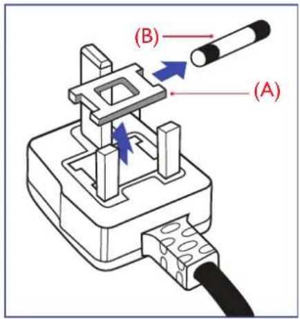
How to connect a plug:
The wires in the mains lead are coloured in accordance with the following code:
BLUE - "NEUTRAL" ("N")
BROWN - "LIVE" ("L")
GREEN & YELLOW - "EARTH" ("E")
The GREEN & YELLOW wire must be connected to the 1. terminal in the plug which is marked with the letter "E" or by the Earth symbol or coloured GREEN or GREEN & YELLOW.
The BLUE wire must be connected to the terminal which is 2. marked with the letter "N" or coloured BLACK.
The BROWN wire must be connected to the terminal 3. which marked with the letter "L" or coloured RED.
Before replacing the plug cover, make certain that the cord grip is clamped over the sheath of the lead - not simply over the three wires.

natural_image
Diagram of a battery pack with colored wires (green, blue, red) and connectors, no text or symbols presentNorth Europe (Nordic Countries) Information
Placering/Ventilation
VARNING: FÖRSÄKRA DIG OM ATT HUVUDBRYTARE OCH UTTAG ÄR LÄTÄTKOMLIGA, NÄR DU STÄLLER DIN UTRUSTNING PÅPLATS.
Placering/Ventilation
ADVARSEL: S∅RG VED PLACERINGEN FOR, AT NETLEDNINGENS STIK OG STIKKONTAKT ER NEMT TILGÆNGELIGE.
Paikka/Ilmankierto
VAROITUS: SIJOITA LAITE SITEN, ETTÄ VERKKOJOHTO VOIDAAAN TARVITTAESSA HELPOSTI IRROTTAA PISTORASIASTA.
End-of-Life Disposal
Your new Public Information Display contains materials that can be recycled and reused.
Specialized companies can recycle your product to increase the amount of reusable materials and to minimize the amount to be disposed of.
Please find out about the local regulations on how to dispose of your old display from your local dealer.
Waste Electrical and Electronie Equipment-WEEE
Attention users in European Union private households

This marking on the product or on its packaging illustrates that, under European Directive 2002/96/EG governing used electrical and electronic appliances, this product may not be disposed of with normal household waste. You are responsible for disposal of this equipment through a designated waste electrical and electronic equipment collection. To determine the locations for dropping off such waste electrical and electronic, contact your local government office, the waste disposal organization that serves your household or the store at which you purchased the product.
REGULATORY INFORMATION
Attention users in United States:
Like all LCD products, this set contains a lamp with Mercury. Please dispose of according to all Local, State and Federal Laws. For the disposal or recycling information, contact: www.mygreenelectronics.com or www.eiae.org.
End of Life Directives-Recycling

Your new Public Information Display contains several materials that can be recycled for new users.
Like all LCD produces, this set contains a lamp with Mercury. Please dispose of according to all Local, State, and Federal laws.
CHAPTER 1: UNPACKING AND INSTALLATION
Unpacking1.1.
- This product is packed in a carton, together with the standard accessories.
Any other optional accessories will be packed separately. - Due to the size and weight of this display it is recommended for two people to move it.
• After opening the carton, ensure that the content is in good condition and complete.
Package Contents1.2.
Please verify that you received the following items with your package content:
LCD display•
CD•
Remote control with AAA • batteries
Power cord (1.8 m)•
VGA cable (1.8 m)•
Power switch cover•
Screw for Power switch • cover (M3x8)
Cable tie•

natural_image
Blank white rectangle with a light blue gradient background (no text or symbols)
Power Cord

Power switch cover and screw (M3x8) x1

Video Signal Cable (D-SUB to D-SUB Cable)

Remote Control and AAA Batteries

CD ROM

Cable tie
NOTES:
- Please make sure that for all other regions, apply a power cord that conforms to the AC voltage of the power socket and has been approved by and complies with the safety regulations of the particular country.
- You might like to save the package box and packing material for shipping the display.
1.3. Installation Notes
- Due to the high power consumption, always use the plug exclusively designed for this product. If an extended line is required, please consult your service agent.
- The product should be installed on a flat surface to avoid tipping. The distance between the back of the product and the wall should be maintained for proper ventilation. Avoid installing the product in the kitchen, bathroom or any other places with high humidity so as not to shorten the service life of the electronic components.
- The product can normally operate only under 3000m in altitude. In installations at altitudes above 3000m, some abnormalities may be experienced.
Installing and Removing Table Stands (optional)1.4.
To install table stands1.4.1.
Ensure your display is powered off.1.
Spread a protective sheet on a flat surface.2.
Grab the carrying handles and place the display face-down on the protective sheet. 3.
After inserting the stand in the guide block, tighten the screws on both sides of the display.4.
NOTE: The longer side of the stand should face the front of the display.

To remove table stands1.4.2.
Power off the display.1.
Spread a protective sheet on a flat surface.2.
Grab the carrying handles and place the display face-down on the protective sheet. 3.
Remove screws using a screwdriver and place them in a safe place for reuse.4.
Mounting on a Wall1.5.
To mount this display to a wall, you will have to obtain a standard wall-mounting kit (commercially available). We recommend using a mounting interface that complies with TUV-GS and/or UL1678 standard in North America.

Lay a protective sheet on a table, which was wrapped around the display when it was packaged, 1. beneath the screen surface so as not to scratch the screen face.
Ensure you have all accessories for mounting this display (wall mount, ceiling mount, table 2. stand, etc).
Follow the instructions that come with the base mounting kit. Failure to follow correct mounting 3. procedures could result in damage to the equipment or injury to the user or installer. Product warranty does not cover damage caused by improper installation.
For the wall-mounting kit, use M6 mounting screws (having a length 10 mm longer than the 4. thickness of the mounting bracket) and tighten them securely.
VESA Grid1.5.1.
| PS-46 400 (H) x 400 (V) | 400 (H) x 200 (V) |
| PS-55 | 200 (H) x 200 (V) |

Caution:
To prevent the display from falling:
- For wall or ceiling installation, we recommend installing the display with metal brackets which are commercially available. For detailed installation instructions, refer to the guide received with the respective bracket.
To lessen the probability of injury and damage resulting from fall of the display in case of • earthquake or other natural disaster, be sure to consult the bracket manufacturer for installation location.
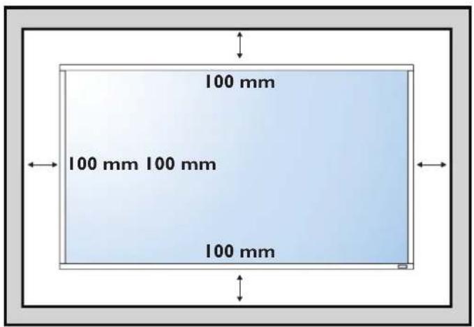
Ventilation Requirements for enclosure locating1.5.2.
To allow heat to disperse, leave space between surrounding objects as shown in the diagram below.
CHAPTER 2: PARTS AND FUNCTIONS
2.1. Control Panel

① POWER button
Use this button to turn the display on or put the display to standby.
② MUTE button
Switch the audio mute ON/OFF.
③ INPUT button
Use this button to select the input source.
④ [−] button
- Increase the adjustment while OSD menu is on, or increase the audio output level while OSD menu is off.
• Used as [SET] button in the On-Screen-Display menu.
⑤ [+]button
Decrease the adjustment while OSD menu is on, or decrease the audio output level while OSD menu is off.
⑥ [▲button
Move the highlight bar up to adjust the selected item while OSD menu is on.
⑦ [▼button
Move the highlight bar down to adjust the selected item while OSD menu is on.
⑧ MENU button
Return to previous menu while OSD menu is on, or to activate the OSD menu when OSD menu is off.
NOTE: "Keyboard Control Lock Mode"
This function completely disables the access to all Keyboard Control functions. To enable or disable the keyboard control lock, press both ( [+] and ( [+ ) buttons and hold down continuously for more than 3 (three) seconds.
⑨ Remote control sensor and power status indicator
- Receives command signals from the remote control.
-
Indicates the operating status of the display without OPS:
-
Lights green when the display is turned on
- Lights red when the display is in standby mode
- Lights amber when the display enters APM mode
- When {SCHEDULE} is enabled, the light blinks green and red
- If the light blinks red, it indicates that a failure has been detected
- Lights off when the main power of the display is turned off
PARTS AND FUNCTIONS
- Indicates the operating status of the display with OPS:
- Lights green when the display is on, but the OPS is off
- Lights blue when the display and the OPS is on
- Lights red when the display is in standby mode
- Lights amber when the display enters APM mode
- When {SCHEDULE} is enabled, the light blinks green and red
- If the light blinks red, it indicates that a failure has been detected
- Lights off when the main power of the display is turned off
▲ NOTE: Developed by Intel, Open Pluggable Specification (OPS) is an industry standard interface, with which display can be upgraded with signage function. Any PC module or media player compatible with OPS standard for public displays can work with AG Neovo PS-Series display, without being limited by different specifications.
Input/Output Terminals

① AC IN
AC power input from the wall outlet.
② MAIN POWER SWITCH
Switch the main power on/off.
③ RS232C OUT
RS232C network output for the loop-through function.
④ RS232C IN
RS232C network input for the loop-through function.
⑤ RJ-45
LAN port connection from your OPS device.
⑥ HDMI IN
HDMI video/audio input.
⑦ DisplayPort
DisplayPort video input.
⑧ DVI IN
DVI-D video input.
⑨ DVI OUT / VGA OUT
DVI or VGA video output.
⑩ VGA IN (D-Sub)
VGA video input.
⑪ PC AUDIO IN
Audio input for VGA/DVI source (3.5mm stereo phone).
⑫ COMPONENT IN (BNC)
Component YPbPr video source input.
⑬ SPEAKERS SWITCH
Internal speaker on/off switch.
⑭ AUDIO IN
Audio input from external AV device (RCA).
⑮ AUDIO OUT (RCA)
Audio output from the AUDIO IN jack to an external AV device.
⑯ SPEAKERS OUT
External speakers output.
⑰ KENSINGTON LOCK
Used for security and theft prevention.
⑱ OPS SLOT
Designed to simplify the changing, maintenance, and upgrading of a OPS PC module or a OPS media player.
Remote Control2.3.

2.3.1 General functions
① [POWER] button
Press to switch on the display from standby mode. Press again to turn it off and back into standby mode.
② [SMART] button
Press to activate Smart Menu. Press [▲] or [▼] button to select menu options. Press [SET] button to confirm and exit the selection.
Standard• : Used for normal images (factory setting)
Highbright• : Used for moving image such as Video
sRGB• : Used for text based images
③ [PIP] (Picture In Picture) button
[ON/OFF]: Turn PIP mode ON/OFF.
[INPUT]: Select the input signal for the sub-picture.
[CHANGE]: Toggle between the main picture and sub picture.
④ [CONTRAST] button
Press to activate Contrast Menu. Press [+] or [+button to adjust the value. Press [MENU] button to confirm and exit.
⑤ [DISPLAY] button
Press to turn on/off the information OSD displayed on the upper right corner of the screen.
⑥ [+]button
- Press to move the selection left in OSD menu.
- Press to decrease the value in OSD menu.
- Press to move the sub-picture left in PIP mode.
⑦ [SET] button
Press to activate the setting inside the OSD menu.
⑧ [AUTO ADJUST] button
Press to run the Auto Adjust function.
▲ NOTE: This button is functional for VGA input only.
⑨ [MUTE] button
Press to turn the mute function on/off.
⑩ [VIDEO SOURCE] button
Press to toggle Video Source Menu. Press [▲] or [▼] button to select one of the video sources among DisplayPort, DVI-D, VGA, HDMI, Component, Video, or Card OPS. Press [SET] button to confirm and exit.
⑪ [AUDIO SOURCE] button
Press to toggle Audio Source Menu. Press [▲] or [▼] button to select one of the audio sources among DisplayPort, HDMI, Audio1, Audio2, or Card OPS. Press [SET] button to confirm and exit.
PARTS AND FUNCTIONS
⑫ Picture Format button
Press to switch screen aspect ratio.
• For PC signal: FULL, NORMAL, CUSTOM and REAL.
• For Video signal: FULL, NORMAL, DYNAMIC, CUSTOM, REAL, and 21:9.
⑬ [BRIGHTNESS] button
Press to toggle Brightness Menu. Press [+] or [+button to adjust the value. Press [MENU] button to confirm and exit.
⑭ [▲button
Press to move the selection up in OSD menu.
Press to move the sub-picture up in PIP mode.
⑮ [MENU] button
Press to turn the OSD menu on/off.
⑯ [+] button
Press to move the selection right in OSD menu.
Press to increase the value in OSD menu.
Press to move the sub-picture right in PIP mode.
⑰ [EXIT] button
Press to turn back to the previous OSD menu.
⑱ [▼button
Press to move the selection down in OSD menu.
Press to move the sub-picture down in PIP mode.
⑲ [VOL UP] button
Press to increase the audio output level.
⑳ [VOL DOWN] button
Press to decrease the audio output level.
Inserting the batteries in the remote control2.3.2
The remote control is powered by two 1.5V AAA batteries.
To install or replace batteries:

Press and then slide the cover to open it. 1.
Align the batteries according to the (+) and (−) indications inside the battery compartment2.
3. Replace the cover.
Caution:
The incorrect use of batteries can result in leaks or bursting. Be sure to follow these instructions:
- Place “AAA” batteries matching the (+) and (−) signs on each battery to the (+) and (−) signs of the battery compartment.
Do not mix battery types.
Do not combine new batteries with used ones. It causes shorter life or leakage of batteries.
Remove the dead batteries immediately to prevent them from liquid leaking in the battery • compartment. Don't touch exposed battery acid, it can damage your skin.
▲ NOTE: If you do not intend to use the remote control for a long period, remove the batteries.
Handling the remote control2.3.3
Do not subject to strong shock.
- Do not allow water or other liquid to splash the remote control. If the remote control gets wet, wipe it dry immediately.
Avoid exposure to heat and steam.
Other than to install the batteries, do not open the remote control.
Operating range of the remote control2.3.4
Point the top of the remote control toward the display's remote control sensor when pressing a button.
Use the remote control within a distance of less than 10m/33ft from the display's sensor, and a horizontal and vertical angle of less than 30 degrees.
▲ NOTE: The remote control may not function properly when the remote control sensor on the display is under direct sunlight or strong illumination, or when there is an obstacle in the path of signal transmission.

CHAPTER 3: CONNECTING EXTERNAL EQUIPMENT
3.1 Using the Switch Cover
A cover for the power switch is provided to prevent the display from being turned on or off accidentally.
To lock the cover into position:
- Align and insert the cover to the indentation located beside the power switch.
- Use the screw to lock the cover.

natural_image
Technical line drawing of a computer chassis with mounting hardware and internal components (no text or symbols)3.2 Connecting External Equipment (DVD/VCR/VCD)
3.2.1 Using COMPONENT video input
![Audio Out [ R ] [L ] [ AUDIO IN ] COMPONENT OUT (YPbPr) DVD / VCR / VCD [COMPONENT IN] (YPbPr)](/content/2026/05/963775/images/245b68bc1a4f937fdbbf8c5dee2f59a93b23ed9866f4b4b9f622f6965a3bf12e.jpg)
CONNECTING EXTERNAL EQUIPMENT
3.2.2 Using HDMI video input
![DVD / VCR / VCD HDMI Out [HDMI IN]](/content/2026/05/963775/images/eb0082004b8b7e205065fc52a32928c4c83175186daa7b2cf92f9cb67e9946b5.jpg)
3.3 Connecting a PC
3.3.1 Using VGA input
![[R] [L] [AUDIO IN] VGA Out D-Sub 15 pin PC Audio Out [VGA IN] [PC AUDIO IN]](/content/2026/05/963775/images/a323db034bcaa1e4b730c2d5702d39ccd7b35540ecc26a291c8569095ad7e49a.jpg)
3.3.2 Using DVI input
![[R] [L] [AUDIO IN] [DVI IN] DVI Out PC Audio Out [PC AUDIO IN]](/content/2026/05/963775/images/922f431c5b2114cff02fb516abb34fc97f32b726a58e558e0a5562cf15c4368b.jpg)
3.3.3 Using HDMI input
![HDMI Out [HDMI IN] PC](/content/2026/05/963775/images/4f89f1e3e8b027813a4443ef21512f9048211e619292608f07c4d2ec8215384d.jpg)
3.4 Connecting Audio Equipment
3.4.1 Connecting external speakers

3.4.2 Connecting an external audio device
![Audio In [R] [L] [AUDIO OUT] Stereo Amplifier](/content/2026/05/963775/images/c4d3f88e7460d75c6cfdacaa681594f82a67f756fb7dd06bb3cb5b94ecdfb456.jpg)
CONNECTING EXTERNAL EQUIPMENT
Connecting Multiple Displays in a Daisy-chain Configuration3.5
You can interconnect multiple displays to create a daisy-chain configuration for applications such as a video wall.
NOTE: Maximum 25 displays (5x5) can be used in a daisy-chain configuration.
Display control connection3.5.1
Connect the [RS232C OUT] connector of DISPLAY 1 to the [RS232C IN] connector of DISPLAY 2.

flowchart
graph TD
    A["PC"] --> B["RS-232C IN"]
    B --> C["RS-232C OUT"]
    C --> D["RS-232C IN"]
    D --> E["RS-232C OUT"]
    E --> F["RS-232C IN"]
    F --> G["RS-232C OUT"]
    G --> H["RS-232C IN"]
    H --> I["RS-232C OUT"]
    I --> J["RS-232C IN"]
    J --> K["RS-232C OUT"]
    K --> L["RS-232C IN"]
    L --> M["RS-232C OUT"]
    M --> N["RS-232C IN"]
    N --> O["RS-232C OUT"]
    O --> P["RS-232C IN"]
    P --> Q["RS-232C OUT"]
    Q --> R["RS-232C IN"]
    R --> S["RS-232C OUT"]
    S --> T["RS-232C IN"]
    T --> U["RS-232C OUT"]
    U --> V["RS-232C IN"]
    V --> W["RS-232C OUT"]
    W --> X["RS-232C IN"]
    X --> Y["RS-232C OUT"]
Digital video connection3.5.2
Connect the [DVI OUT / VGA OUT] connector of DISPLAY 1 to the [DVI IN] connector of DISPLAY 2.

flowchart
graph TD
    A["PC"] --> B["Display 1"]
    B --> C["DVI IN"]
    B --> D["DVI"]
    B --> E["DVI/VGA OUT"]
    B --> F["DVI IN"]
    B --> G["DVI"]
Analog video connection3.5.3
Connect the [DVI OUT / VGA OUT] connector of DISPLAY 1 to the [VGA IN] connector of DISPLAY 2.

flowchart
graph TD
    A["PC"] --> B["Device 1"]
    B --> C["VGA IN"][VGA]
    B --> D["DVI/VGA OUT"]
    C --> E["Device 2"]
    D --> E
    style A fill:#f9f,stroke:#333
    style B fill:#ccf,stroke:#333
    style C fill:#cfc,stroke:#333
    style D fill:#fcc,stroke:#333
CHAPTER 4: OSD MENU
An overall view of the On-Screen Display (OSD) structure is shown below. You can use it as a reference for further adjusting your display.
Navigating the OSD Menu4.1
Navigating the OSD menu using the remote control4.1.1

flowchart
graph TD
    A["SET"] --> B["←"]
    A --> C["+"]
    A --> D["▼"]
    A --> E["→"]
    F["MENU"] --> A
    G["EXIT"] --> A
Press [1. MENU] button on the remote control to display the OSD menu.
Press [▲] or [▼button to choose the item you want to adjust.
Press [3. SET] button to enter the submenu.
In the submenu, press [▲] or [▼button to toggle among items, press [ ] or [ ] button to adjust settings. If there is a submenu, press [SET] button to enter the submenu.
Press [EXIT] button to return to the previous menu, or press [MENU] button to exit the OSD 5. menu.
Navigating the OSD menu using the display's control buttons4.1.2
Press [1. MENU] button to display the OSD menu.
Press [2:] or [+button to choose the item you want to adjust.
Press [3. SOURCE] button to enter the submenu.
In the submenu, press [4] or [▼button to toggle among items, press [ ] or [ ] button to adjust settings. If there is a submenu, press [SOURCE] button to enter the submenu.
- Press [MENU] button to return to the previous menu, or press [MENU] button several times to exit the OSD menu.
OSD Menu Overview4.2
PICTURE menu4.2.1
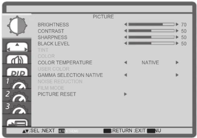
| Item Description | |
| BRIGHTNESS Adjust | st the overall image brightness by changing the intensity of the LCD panel's backlight. |
| CONTRAST Adjust to sharpen the picture quality. The black portions of the picture become richer in darkness and the white become brighter. | |
| SHARPNESS Adjust to improve the image detail. | |
| BLACK LEVEL Adjust to change the image brightness. | |
| TINT | Use the [+] or [+button to adjust. Press the [ ]-button and the flesh tone color turns slightly green. Press the [+button and the flesh tone color turns slightly purple.NOTE: This item is functional for HDMI(Video mode), S-Video, Video, and YPbPr inputs only. |
| COLOR | Adjust to increase or decrease the intensity of colors in the image.NOTE: This item is functional for HDMI(Video mode), S-Video, Video, and YPbPr inputs only. |
| COLOR TEMPERATURE | Select a color temperature for the image. A lower color temperature will have a reddish tint, whilst a higher color temperature gives off a more bluish tint.The options are: {3000K} / {4000K} / {5000K} / {6500K} / {7500K} / {9300K} / {10000K} / {NATIVE} / {USER}. |
| USER COLOR | With this function you can adjust the color tones of the image precisely by changing the R (Red), G (Green) and B (Blue) settings independently.NOTE: This item is functional only when {COLOR TEMPERATURE} is set to {USER}. |
| GAMMA SELECTION | Gamma is what controls the overall brightness of an image. Images which are not corrected properly can appear too white or too dark, so controlling the gamma properly can have a huge influence on the overall picture quality of your display.The options are: {NATIVE} / {2.2} / {2.4} / {S GAMMA}. |
| NOISE REDUCTION | Adjust to remove the noise in the image. You can select a suitable noise reduction level.The options are: {OFF} / {LOW} / {MIDDLE} / {HIGH}.⚠ NOTE: This item is functional for HDMI(Video mode), S-Video, Video, and YPbPr inputs only. |
| FILM MODE Choose | to turn on or off the film mode frame conversion function.{AUTO} - Enable the film mode frame conversion function for movies and motion pictures. The display converts a 24 frames-per-second (24 fps) input signal format to DVD video signal format. Once this function is enabled, it is recommended that you set the {SCAN CONVERSION} function to {PROGRESSIVE}.{OFF} - Disable the film mode frame conversion function. This mode is suitable for TV broadcasting and VCR signals. |
| PICTURE RESET | Reset all settings in the Picture menu to factory preset values. |
SCREEN menu4.2.2
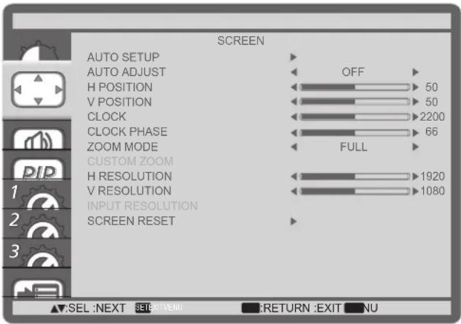
| Item Description | |
| AUTO SETUP | Use this function to let the display automatically optimize the display of VGA input image.⚠️ NOTE: This item is functional for VGA input only. |
| AUTO ADJUST | Choose to let the display detect and display available signal sources automatically.• {ON} - Set the display to display the image automatically once a signal is connected.• {OFF} - Once a signal is connected, it can only be selected manually. |
| H POSITION | Press the [+] button to move the image to the right, or [−] to move the image to the left. |
| V POSITION | Press the [+] button to move the image up, or [−] to move the image down. |
| CLOCK | Adjust the width of the image.⚠️ NOTE: This item is functional for VGA input only. |
| CLOCK PHASE | Adjust to improve the focus, clarity and stability of the image.⚠️ NOTE: This item is functional for VGA input only. |
Item Description
| ZOOM MODE The pictures you receive may be transmitted in 16:9 format (wide screen) or 4:3 format (conventional screen). The 16:9 pictures sometimes have a black band at the top and bottom of the screen (letterbox format).This function allows you to optimize the picture display on screen. The following zoom modes are available for:PC mode: {FULL} / {NORMAL} / {CUSTOM} / {REAL}.Video mode: {FULL} / {NORMAL} / {DYNAMIC} / {CUSTOM} / {REAL}. | |
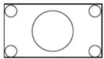 | FULLThis mode restores the correct proportions of pictures transmitted in 16:9 using the full screen display. |
 | NORMALThe picture is reproduced in 4:3 format and a black band is displayed on either side of the picture. |
 | DYNAMICFill the entire screen by stretching 4:3 pictures non-proportionally. |
| CUSTOMChoose to apply the custom zoom settings in the Custom Zoom submenu. | |
| REALThis mode displays the image pixel-by-pixel on screen without scaling the original image size. | |
Item Description
| CUSTOM ZOOM You can use this function to further customize the zoom settings to suit the image you want to display.▲NOTE: This item is functional only when the {ZOOM MODE} setting is set to {CUSTOM}. | |
 | ZOOMExpands the horizontal and vertical sizes of the image simultaneously. |
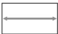 | H ZOOMExpands the horizontal size of the image only. |
 | V ZOOMExpands the vertical size of the image only. |
 | H POSITIONMoves the horizontal position of the image left or right. |
 | V POSITIONMoves the vertical position of the image up or down. |
| INPUT RESOLUTION | Set the resolution of the VGA input. This is only required when the display is unable to detect the VGA input resolution correctly.▲NOTE: This item is functional for VGA input only.The options are:{1024x768 / 1280x768 / 1360x768}{1400x1050 / 1680x1050}{1600x1200 / 1920x1200}{Auto}: Determines the resolution automatically.The selected settings will become effective after turning off the power and turn it on again. |
| SCREEN RESET | Reset all settings in the SCREEN menu to factory preset values. |
AUDIO menu4.2.3

| Item Description | |
| BALANCE Adjust to | emphasize left or right audio output balance. |
| TREBLE Adjust to in | crease or decrease higher-pitched sounds. |
| BASS Adjust to incre | ase or decrease lower-pitched sounds. |
| AUDIO RESET | Reset all settings in the AUDIO menu to factory preset values. |
PIP menu4.2.4

| Item Description | |
| PIP MODE Select the | PIP (Picture-in-Picture) mode.The options are: {OFF} / {PIP} / {POP} / {SBS ASPECT} / {SBS FULL}. |
| PIP SIZE Select the | size of the sub picture in the PIP (Picture-in-Picture) mode.The options are: {SMALL} / {MIDDLE} / {LARGE}. |
| PIP AUDIO Select the | audio source in the PIP (Picture-in-Picture) mode.{MAIN AUDIO} - Select audio from the main picture{SUB AUDIO} - Select audio from the sub picture. |
| PIP H POSITION | Adjust the horizontal placement of the sub picture. |
| PIP V POSITION | Adjust the vertical placement of the sub picture. |
| SUB INPUT | Select the input signal for the sub-picture. |
Item Description
PIP RESET Reset al
settings in the PIP menu to factory preset values.
NOTES:
- The PIP function is available only for certain signal source combinations as shown in the table below.
- The availability of the PIP function will also depend on the resolution of the input signal being used.
| Sub Picture\Main Picture | DVI VGA HDMI | YPbPr DisplayPort | Video Card OPS | ||||
| DVI | X | O | X | O | X | O | X |
| VGA | O | X | O | X | O | O | O |
| HDMI | X | O | X | O | X | O | X |
| YPbPr | O | X | O | X | O | X | O |
| DisplayPort | X | O | X | O | X | O | X |
| Video | O | O | O | X | O | X | O |
| Card OPS | X | O | X | O | X | O | X |
(O: PIP function available, X: PIP function unavailable)
By pressing the [PIP ON/OFF] button on the remote control, you can change the mode in the order shown below:

flowchart
graph LR
    A["PIP POP"] --> B["A"]
    B --> C["SBS ASPECT SBS FULL"]
    C --> D["A B"]
    D --> E["OFF"]
The resolutions in the PIP and POP modes are configured as follows:
PIP SIZE {SMALL} : 320 x 240 pixels
{MIDDLE} : 480 x 320 pixels
{LARGE} : 640 x 480 pixels
POP SIZE: 474 x 355 pixels
NOTE: The images displayed in the sub picture always fit the PIP sizes shown above irrespective of the aspect ratio of the input image.
CONFIGURATION1 menu4.2.5

| Item Description | |
| OFF TIMER Set the | display to turn itself off to standby mode within an amount of time specified.The options are: {OFF, 1HOUR ~ 24HOURS} from current time. |
SCHEDULE This function allows you to program up to 7 (seven) different scheduled time intervals for the display to activate.You can select:The time for the display to turn on and turn off.•The days in a week for the display to activate.•Which input source the display will use for each scheduled activation period.NOTE: You should set up current date and time in {DATE AND TIME} menu before using this function.Press [SET] button to enter the submenu. 2. Press [▲] or [▼] button to select a schedule item (item number 1 ~ 7), and then press [SET] button to mark it the item number. 2. Press [▲] or [▼] button to select a schedule item (item number 1 ~ 7), and then press [SET] button to mark it the item number.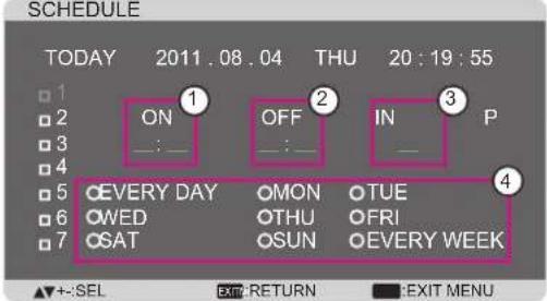 | |
Item Description
| Press [3.] or [-] button to select the schedule:1 POWER-ON schedule: Press [ ] or [ ] button to set the hour and minute for the display to turn on.2 POWER-OFF schedule: Press [▲] or [ ]▼button to set the hour and minute for the display to turn off.Select or leave an empty “__” for both the hour and minute slot if you do not want to use this power-on or power-off schedule.3 INPUT-SOURCE selection: Press [▲] or [▼] button to select an input source. If no input source is selected, the input source will remain the same as last selected.4 DATE schedule: Press [+] button to select which day in a week this schedule item will be take effect, and then press the [SET] button.For more schedule settings, press [4. EXIT] button and then repeat the steps above. A check mark in the box next to the number of the schedule item indicates that the selected schedule is in effect.▲ NOTES:· The {EVERY DAY} selection in a schedule item takes priority over the other weekly schedules.· If the schedule overlap, the scheduled power-on time takes priority over scheduled power-off time.If there are two schedule items programmed for the same time, the · highest numbered schedule takes priority. For example, if schedule items #1 and #2 both set the display to power on at 7:00 AM and off at 5:00 PM, then only schedule item # 1 will take effect. | |
| DATE AND TIME | Adjust the current date and time for the display's internal clock. Press [1. SET] button to enter the submenu.Press [▲] or [▼] button to toggle among the {YEAR}, {MONTH}, {DAY}, {HOUR}, {MINUTE}, and {DAYLIGHT SAVING TIME} settings.Press [3.] or [-] button to adjust all settings except {DAYLIGHT SAVING TIME}. Press [1. SET] button to enter the submenu.Press [▲] or [▼] button to toggle among the {YEAR}, {MONTH}, {DAY}, {HOUR}, {MINUTE}, and {DAYLIGHT SAVING TIME} settings.Press [3.] or [-] button to adjust all settings except {DAYLIGHT SAVING TIME}. |
| CONFIGURATION1 RESET | Reset all settings in the CONFIGURATION1 menu to factory preset values. |
CONFIGURATION2 menu4.2.6
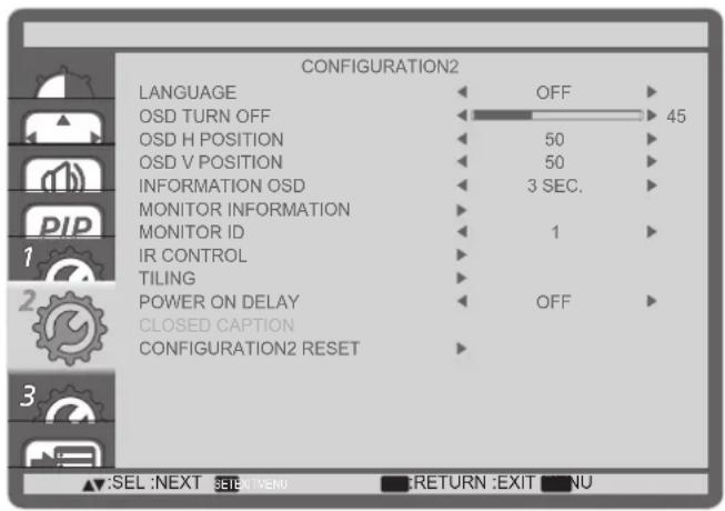
| Item Description | |
| LANGUAGE Select the language used in the OSD menu.The options are: {ENGLISH} / {DEUTSCH} / {FRANÇAIS ITALIANO ESPAÑOL / {SVENSKA}. 日本語 中文 | |
| OSD TURN OFF | Set the period of time the OSD menu stays on the screen.The options are: {5 ~ 120} seconds. |
| OSD H POSITION | Adjust the horizontal p Set the period of time the OSD menu stays on the screen.The options are: {5 ~ 120} seconds. osition of the OSD menu. |
| OSD V POSITION | Adjust the vertical position of the OSD menu. |
| INFORMATION OSD | Set the period of time the information OSD displayed on the upper right corner of the screen. The information OSD will display when input signal is changed.The information OSD will remain on the screen with {OFF} selection.The options are: {OFF, 3 SEC. ~ 10 SEC.}. |
| MONITOR INFORMATION | Displays the information about your display, including MODEL NAME and SERIAL. |
| MONITOR ID | Set the ID number for controlling the display via the RS232C connection.Each display must have a unique ID number when multiple sets of this display are connected. |
| IR CONTROL | Select the operation mode of the remote control unit when multiple displays are connected via the RS232C connection.{NORMAL}- All displays can be operated normally by the remote control.{LOCK}- Lock the remote control function of this display. To unlock, press and hold the [DISPLAY] button on the remote control for 5 (five) seconds. |
Item Description
TILING With this function you can create a single large-screen matrix (video wall) that consists of up to 25 sets of this display (up to 5-set each at the vertical and horizontal side). This function requires a daisy-chain connection.

Example: 2 x 2 screen matrix (4 displays)
H MONITORS = 2 displays
V MONITORS = 2 displays
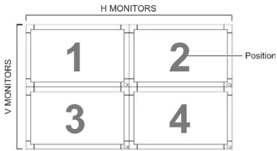
Example: 5 x 5 screen matrix (25 displays)
H MONITORS = 5 displays
V MONITORS = 5 displays

heatmap
H MONITORS | Position | 1 | 2 | 3 | 4 | 5 | | :--- | :--- | :--- | :--- | :--- | :--- | | V MONITORS | 6 | 7 | 8 | 9 | 10 | | H MONITORS | 1112 | 1314 | 15 | | | | H MONITORS | 1617 | 1819 | 20 | | | | H MONITORS | 2122 | 2324 | 25 | | | Position• H MONITORS - Select the number of displays on the horizontal side.
• V MONITORS - Select the number of displays on the vertical side.
- POSITION - Select the position of this display in the screen matrix.
- FRAME COMP. - Choose to turn the frame compensation function on or off. If turned on, the display will adjust the image to compensate for the width of the display bezels in order to accurately display the image.
- ENABLE: Choose to enable or disable the Tiling function. If enabled, the display will apply the settings in {H MONITORS}, {V MONITORS}, {POSITION}, and {FRAME COMP.}.
NOTE: The Tiling function will be disabled when the [ON/OFF] button for PIP is pressed.
| Item Description | |
| POWER ON DELAY | Select the delayed time until the power-on mode is activated after the power is turned on manually or automatically. This setting is useful in hiding start-up messages and powering on the connected devices at different timings.The options are: {OFF}, {2 SEC.}, {4 SEC.}, {6 SEC.}, {8 SEC.}, {10 SEC.}, {20 SEC.}, {30 SEC.}, {40 SEC.}, {50 SEC.}. |
| CLOSED CAPTION | Choose to display or hide captions.NOTE: This item is functional for S-VIDEO or VIDEO input only.{• OFF} - Captions are hidden.{CC1} - Captions are displayed in sync with the primary audio.{CC2} - Information (related to the primary audio) is displayed without sync.{CC3} - Captions are displayed in sync with the secondary audio.{CC4} - Information (related to the secondary audio) is displayed without sync.{TT1 / TT2 / TT3 / TT4} - Four types of information not related to the displayed images are displayed. (For example, news and weather forecast.)NOTE: Check with each supplier of your video software and external video devices in advance whether they are compliant with EIA-608-A. If their video signals are not compliant with it, images may not be displayed correctly. |
| CONFIGURATION2 RESET | Reset all settings in the CONFIGURATION2 menu to factory preset values. |
CONFIGURATION3 menu4.2.7
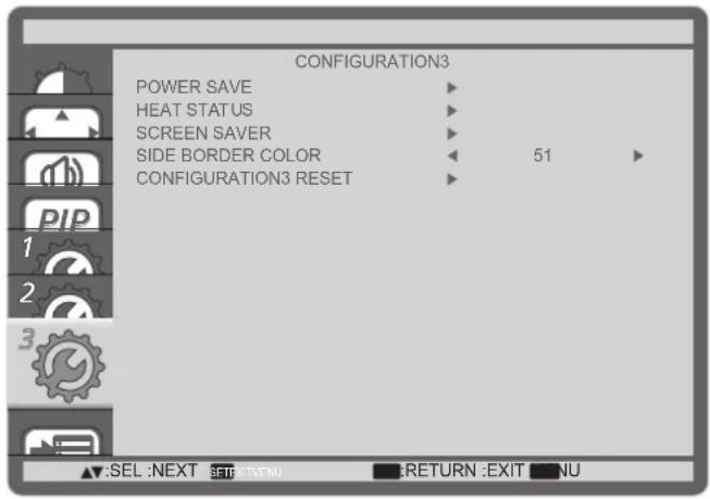
| Item Description | |
| POWER SAVE Set the display to reduce the power automatically. | |
 ·{RGB} - Select {ON} to let the display enter APM mode with no signal detected from the HDMI Graphic mode, HDMI, DVI-D, or VGA inputs after three successive cycles.·{VIDEO} - Select {ON} to let the display enter power saving mode with no signal detected from the HDMI Video mode or YPbPr inputs after three successive cycles. ·{RGB} - Select {ON} to let the display enter APM mode with no signal detected from the HDMI Graphic mode, HDMI, DVI-D, or VGA inputs after three successive cycles.·{VIDEO} - Select {ON} to let the display enter power saving mode with no signal detected from the HDMI Video mode or YPbPr inputs after three successive cycles. | |
| HEAT STATUS This function allows you to check the thermal status of the display at any time. | |
 | |
| SCREEN SAVER | 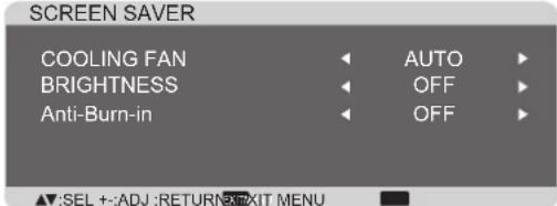 ·{COOLING FAN} - Select {ON} to turn on the cooling fan all the time. Select {AUTO} to turn on/off the cooling fan according to the display's temperature. ·{COOLING FAN} - Select {ON} to turn on the cooling fan all the time. Select {AUTO} to turn on/off the cooling fan according to the display's temperature. |
| SCREEN SAVER | ▲ NOTES:The default {AUTO} option will start running the cooling fan if the temperature of 65°C (152°F) is reached, and will keep running for 30 minutes after cooling down to the temperature of 62°C (144°F).A temperature-warning message will be shown on the screen once the temperature reaches 79°C. All key function except [Power] key will then be disabled.{BRIGHTNESS} - Select {ON} and the brightness of the image will be reduced to an appropriate level, and the Brightness setting in the Picture menu will become unavailable.{Anti-Burn-in} - Choose to enable the panel saving functions to reduce the risk of the “image persistence”. Select the time interval ({10 ~ 900} Seconds / {OFF}) for the display to slightly expand the image size and shift the position of pixels in four directions (up, down, left, or right). |
| SIDE BORDER COLOR | Adjust the brightness of the black areas displayed on both sides of 4:3 images. |
| CONFIGURATION3 RESET | Reset all settings in the CONFIGURATION3 menu to factory preset values. |
ADVANCED OPTION menu4.2.8

| Item Description | |
| INPUT CHANGE | Select the time for input switching as {NORMAL} or {QUICK}.⚠️ NOTE: The selection {QUICK} may cause a slight noise. |
| TERMINAL SETTING | Select the mode to display the HDMI or DVI signal according to their signal format depending on their source device.{•DVI MODE}: Used for DVI-D signal. Select {DVI-PC} when the source device is a PC. Select {DVI-HD} when the source device is a video device.{•HDMI SIGNAL}: Used for HDMI signal. Select {LIMITED} when displaying the signal that uses 16 to 235 levels of 256 levels for each R, G, and B. Select {FULL} when displaying the signal that uses all 256 levels (from level 0 to 255). |
| SCAN CONVERSION | Choose to enable or disable the IP (Interlace to Progressive) conversion function.{PROGRESSIVE}- Enable the IP conversion function (recommended). Once enabled, the interlace input signal will be converted to progressive format for better display quality.{INTERLACE}- Disable the IP function. This mode is suitable for displaying motion pictures, but it increases the chance of image retention. |
| COLOR SYSTEM Selects the Color System depends on your input video format.The options are: {AUTO} / {NTSC} / {PAL} / {SECAM} / {4.43NTSC} / {PAL-60}.▲NOTE: This item is functional for S-VIDEO or VIDEO input only. | |
| SCAN MODE Change the display area of the image.{OVERSCAN}- Display about 95% of the original size of the image. The rest of the areas surrounding the image will be cut off.{UNDERSCAN}- Display the image in its original size.▲NOTE: This item is functional for HDMI-Video timing input only. | |
| SERIAL CONTROL Select the network control port.The options are: {RS-232C} / {LAN}.▲NOTE: If {LAN} is selected, then {RS-232C} will not be activated, even if a cable is attached, and vice versa. | |
| LAN SETTING | Assign {IP ADDRESS}, {SUBNET MASK}, and {DEFAULT GATEWAY} for the display.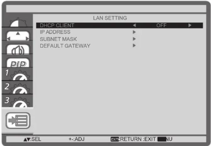 DHCP - Choose to enable or disable the DHCP function. If enabled, the display will be assigned IP address, Subnet mask and Default gateway automatically. If disabled, you will be prompted to enter the following value manually. Finally, press [SET] button to store and save the chosen values. DHCP - Choose to enable or disable the DHCP function. If enabled, the display will be assigned IP address, Subnet mask and Default gateway automatically. If disabled, you will be prompted to enter the following value manually. Finally, press [SET] button to store and save the chosen values. |
| APM Power save setting | {Off} - No signal, direct shutdown. (Default){On} - No signal, enter into Power Save mode. |
| ADVANCED OPTION RESET | Reset all settings in the ADVANCED OPTION menu to factory preset values.Press [1. SET] button to enter the submenu.Press [2] or [▼button to select {YES}, and then press [SET] button to do the reset. |
| FACTORY RESET | Reset all the settings in the OSD menus of {PICTURE}, {SCREEN},{AUDIO}, {PIP}, {CONFIGURATION1}, {CONFIGURATION2},{CONFIGURATION3}, and {ADVANCED OPTION} to factory preset values.Press [1. SET] button to enter the submenu.Press [2] or [▼button to select {YES}, and then press [SET] button to do the reset.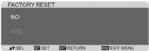 |
VGA Resolution5.1
| Standard Resolution | Active Resolution | Refresh Rate | Pixel Rate | Aspect Ratio | Stand for Mode | |
| H Pixels V | Lines | |||||
| VGA 640 | 480 60 | Hz | 25.175 MHz | 4:3 | Video Graphic Array72 Hz 72 Hz 31.5 M | |
| 75 Hz 75 | Hz 31.5 MHz | |||||
| WVGA 720 | 400 70 Hz | 33.75 MHz | 16:9 | Wide Video Graphic Array | ||
| SVGA 800 | 600 60 | Hz 40 MHz | 4:3 Super VGA | |||
| 75 Hz 75 | Hz 49.5 MHz | |||||
| XGA 1024 | 768 60 | Hz 65 MHz | 4:3 | Extended Graphic Array75 Hz 75 Hz 78.75 | ||
| WXGA | 1280 | 768 | 60 Hz | 79.5 MHz | 5:3 | Wide XGA |
| WXGA | 1280 | 800 | 60 Hz | 79.5 MHz | 16:10 | Wide XGA |
| SXGA | 1280 960 | 60 Hz 108 MHz | 4:3 Super XGA | |||
| SXGA | 1280 | 1024 | 60 Hz | 108 MHz | 5:4 | Super XGA |
| WXGA | 1360 | 768 | 60 Hz | 85.5 MHz | 16:9 | Wide XGA |
| WXGA | 1366 | 768 | 60 Hz | 85.5 MHz | 16:9 | Wide XGA |
| UXGA | 1600 | 1200 | 60 Hz | 162 MHz | 4:3 | Ultra XGA |
| HD1080 | 1920 | 1080 | 60 Hz | 148.5 MHz | 16:9 | HD1080 |
5.2 SDTV Resolution
| Standard Resolution | Active Resolution | Refresh Rate | Pixel Rate | Aspect Ratio | Stand for Mode | |
| H Pixels V | Lines | |||||
| 480i | 720 480 | 29.97 Hz | 13.5 MHz | 4:3 | Modified NTSC Standard | |
| 480p | 59.94 Hz 27 MHz | |||||
| 576i | 720 480 | 25 Hz | 13.5 MHz | 4:3 | Modified PAL Standard | |
| 576p | 50 Hz | 27 MHz | ||||
5.3 HDTV Resolution
| Standard Resolution | Active Resolution | Refresh Rate | Pixel Rate | Aspect Ratio | Stand for Mode | |
| H Pixels V | Lines | |||||
| 720p 128 | 0 720 | 50 Hz | 74.25 MHz | 16:9 | Normally DVB Mode | |
| 60 Hz | ||||||
| 1080i | 1920 | 1080 | 25 Hz | 74.25 MHz | 16:9 | Normally ATSC Mode |
| 30 Hz | ||||||
| 1080p | 1920 | 1080 | 50 Hz | 148.5 MHz | 16:9 | Normally ATSC Mode |
| 60 Hz | ||||||
- The PC text quality is optimum in HD 1080 mode (1920 x 1080, 60Hz).
- Your PC display screen might appear different depending on the manufacturer (and your particular version of Windows).
INPUT MODE
- Check your PC instruction book for information about connecting your PC to a display.
- If a vertical and horizontal frequency-select mode exists, select 60Hz (vertical) and 31.5KHz (horizontal). In some cases, abnormal signals (such as stripes) might appear on the screen when the PC power is turned off (or if the PC is disconnected). If so, press the [INPUT] button to enter the video mode. Also, make sure that the PC is connected.
- When horizontal synchronous signals seem irregular in RGB mode, check PC power saving mode or cable connections.
- The display settings table complies to the IBM/VESA standards, and based on the analog input. The DVI support mode is regarded as same to the PC support mode.
The best timing for the vertical frequency to each mode is 60Hz.
CHAPTER 6: CLEANING AND TROUBLESHOOTING
Cleaning6.1
Caution When Using the Display
- Do not bring your hands, face or objects close to the ventilation holes of the display. The top of the display is usually very hot due to the high temperature of exhaust air being released through the ventilation holes. Burns or personal injuries may occur if any body parts are brought too close. Placing any object near the top of the display could also result in heat related damage to the object as well as the display itself.
- Be sure to disconnect all cables before moving the display. Moving the display with its cables attached may damage the cables and thus cause fire or electric shock.
- Disconnect the power plug from the wall outlet as a safety precaution before carrying out any type of cleaning or maintenance procedure.
Front Panel Cleaning Instructions
- The front of the display has been specially treated. Wipe the surface gently using only a cleaning cloth or a soft, lint-free cloth.
- If the surface becomes dirty, soak a soft, lint-free cloth in a mild detergent solution. Wring the cloth to remove excess liquid. Wipe the surface of the display to remove dirt. Then use a dry cloth of the same type to dry.
Do not scratch or hit the surface of the panel with fingers or hard objects of any kind. - Do not use volatile substances such as insert sprays, solvents and thinners.
Cabinet Cleaning Instructions
• If the cabinet becomes dirty, wipe the cabinet with a soft, dry cloth.
- If the cabinet is extremely dirty, soak a lint-free cloth in a mild detergent solution. Wring the cloth to remove as much moisture as possible. Wipe the cabinet. Use another dry cloth to wipe over until the surface is dry.
- Do not allow any water or detergent to come into contact with the surface of the display. If water or moisture gets inside the unit, operating problems, electrical and shock hazards may result.
Do not scratch or hit the cabinet with fingers or hard objects of any kind.
- Do not use volatile substances such as insert sprays, solvents and thinners on the cabinet.
- Do not place anything made from rubber or PVC near the cabinet for any extended periods of time.
Troubleshooting6.2
| Symptom Possible Cause Remedy | ||
| No picture is displayed The power cord is 1. disconnected.The main power switch on 2. the back of the display is not switched on.The selected input has no 3. connection.The display is in standby 4. mode. | Plug in the power cord.1.Make sure the power switch 2. is switched on.Connect a signal connection to the display. | |
| Interference displayed on the display or audible noise is heard | Caused by surrounding electrical appliances or fluorescent lights. | Move the display to another location to see is the interference is reduced. |
| Color is abnormal The signal cable is not connected properly. | Make sure that the signal cable is attached firmly to the back of the display. | |
| Picture is distorted with abnormal patterns | The signal cable is not 1. connected properly.The input signal is beyond 2. the capabilities of the display. | Make sure that the signal 1. cable is attached firmly.Check the video signal 2. source to see if it is beyond the range of the display. Please verify its specifications with this display's specification section. |
| Display image doesn't fill up the full size of the screen | The zoom mode is not correctly set. | Use the Zoom mode or Custom zoom function in the Screen menu to fine tune display geometry and time frequency parameter. |
| Can hear sound, but no picture | Improperly connected source signal cable. | Make sure that both video inputs and sound inputs are correctly connected. |
CLEANING AND TROUBLESHOOTING
| Can see picture but no sound is heard | Improperly connected source signal cable.Volume is turned all the way down.[3. MUTE] is turned on.No external speaker 4. connected. | 1. Make sure that both video 1. inputs and sound inputs are correctly connected.Press [2. VOL UP] or [VOL DOWN] button to hear sound.Switch MUTE off by using 3. the [MUTE] button.Connect external speakers 4. and adjust the volume to a suitable level. |
| Some picture elements do not light up | Some pixels of the display may not turn on. | This display is manufactured using an extremely high level of precision technology: however, sometimes some pixels of the display may not display. This is not a malfunction. |
| After-Images can still be seen on the display after the display is powered off.(Examples of still pictures include logos, video games, computer images, and images displayed in 4:3 normal mode) | A still picture is displayed for an over extended period of time | Do not allow a still image to be displayed for an extended period of time as this can cause a permanent after-image to remain on the display. |
CHAPTER 7: TECHNICAL SPECIFICATIONS
Display Specifications7.1
| Display PS-46 PS-55 | ||
| Screen Size (Active Area) 46” LCD 55” LCD | ||
| Aspect ratio 16:9 | ||
| Number of pixels 1920 (H) x 1080 (V) | ||
| Pixel pitch 0.53 mm 0.63 mm | ||
| Displayable colors 1073.7M colors | ||
| Brightness (typical) 700 cd/m2 | ||
| Contrast ratio (typical) 4000:1 | ||
| Viewing angle 178 degrees | ||
| In/Out Terminals PS-46 PS | 55 | ||
| Speaker Output | Internal SpeakersExternal Speakers | 10W (L) + 10W (R) [RMS]/8Ω1 Way 1 Speaker System82 dB/W/M/160 Hz ~ 13 KHz | |
| Audio Output | RCA Jack x 2 | 0.5V [rms] (Normal)/ 2 Channel (L+R) | |
| Audio Input | RCA Jack x 23.5 mm Stereo x 1 | 0.5V [rms] (Normal)/ 2 Channel (L+R) | |
| RS232C | D-Sub Jack x 2(9 pin) | TXD + RXD (1:1) | |
| RJ-45 | RJ-45 Jack x 1(8 pin) | 10/100 LAN Port | |
| HDMI Input | HDMI Jack x 1(Type A) (18 pin) | Digital RGB: TMDS (Video + Audio)MAX: Video - 720p, 1080p, 1920 x 1080/60 Hz (WUXGA)Audio - 48 KHz/ 2 Channel (L+R)Supports LPCM only | |
| DVI-D Input | DVI-D jack | Digital RGB: TMDS (Video) | |
| VGA Input | D-Sub Jack x 1(15 pin) | Analog RGB: 0.7V [p-p] (75Ω), H/CS/V: TTL (2.2kΩ),SOG: 1V [p-p] (75Ω)MAX: 720p, 1080p, 1920 x 1080/60 Hz (WUXGA) | |
| DVI-I (DVI & VGA Output) | DVI-I Jack x 1(29 pin) | Digital RGB: TMDS (Video)Analog RGB: 0.7V [p-p] (75Ω), H/CS/V: TTL (2.2kΩ),SOG: 1V [p-p] (75Ω)MAX: 720p, 1080p, 1920 x 1080/60 Hz (WUXGA) | |
| Component Input | BNC Jack x 3 | Y: 1V [p-p] (75Ω), Pb: 0.7V [p-p] (75Ω), Pr: 0.7V [p-p](75Ω)MAX: 480i, 576i, 480p, 576p, 720p, 1080i, 1080p | |
| DisplayPort Input | DisplayPort Jack x 1(20 pin) | Digital RGB: TMDS (Video + Audio)MAX: Video - 720p, 1080p, 1920 x 1080/60 Hz (WUXGA)Audio - 48 KHz/ 2 Channel (L+R)Supports LPCM only | |
TECHNICAL SPECIFICATIONS
| General PS-46 PS-55 | ||
| Power Supply AC 100 ~ 240V, 50 ~ 60Hz AC 100 ~ 240V, 50 ~ 60Hz | ||
| Power Consumption (Max) 250W 310W | ||
| Power Consumption (typ.) 170W 245W | ||
| Power Consumption (Standby & Off) <0.5W (RS232 in active) <0.5W (RS232 in active) | ||
| Dimensions (With Stand) [W x H x D] | 1052.7 x 662.7 x 400 mm 1244.4 x 770.6 x 400 mm | |
| Dimensions (Without Stand) [W x H x D] | 1052.7 x 607.3 x 69 mm 1244.4 x 715.2 x 69 mm | |
| Weight (With Stand) 24.0 Kg 32.6 Kg | ||
| Weight (Without Stand) 22.0 Kg 30.6 Kg | ||
| Gross Weight | 27.5 Kg 36.1 Kg | |
| Environmental Condition | PS-46 PS-55 | ||
| Temperature | Operational | 0 ~ 40°C | |
| Storage | -20 ~ 60°C | ||
| Humidity | Operational | 20 ~ 80% RH (No condensation) | |
| Storage | 5 ~ 95% RH (No condensation) | ||
| Altitude | Operational | 0 ~ 3,000 m | |
| Internal Speaker | PS-46 PS-55 | |
| Type | 1 Way 1 Speaker | |
| Input | 10 W (RMS) | |
| Impedance | 8Ω | |
| Output Sound Pressure | 82 dB/W/M | |
| Frequency Response | 160 Hz ~ 13 KHz | |
NOTE: All specifications are subject to change without prior notice.

- CHAPTER 1: UNPACKING AND INSTALLATION.... 11
- CHAPTER 2: PARTS AND FUNCTIONS ...... 15
- CHAPTER 3: CONNECTING EXTERNAL EQUIPMENT ...... 21
- CHAPTER 4: OSD MENU....26
- TABLE OF CONTENTS
- CHAPTER 5: INPUT MODE 42
- CHAPTER 6: CLEANING AND TROUBLESHOOTING 44
- CHAPTER 7: TECHNICAL SPECIFICATIONS ...... 47
- SAFETY INFORMATION
- Warnings and Precautions
- KNOW THESE SAFETY SYMBOLS
- Read and follow follow these instructions when connecting and using your Public Information Display:
- CE Declaration of Conformity
- Federal Communications Commission (FCC) Notice (U.S. Only)
- Polish Center for Testing and Certification Notice
- Electric, Magnetic and Electronmagnetic Fields ("EMF")
- REGULATORY INFORMATION
- Information for U.K. only
- WARNING - THIS APPLIANCE MUST BE EARTHED.
- How to connect a plug:
- North Europe (Nordic Countries) Information
- End-of-Life Disposal
- Waste Electrical and Electronie Equipment-WEEE
- Attention users in European Union private households
- Attention users in United States:
- End of Life Directives-Recycling
- CHAPTER 1: UNPACKING AND INSTALLATION
- Unpacking1.1.
- Package Contents1.2.
- NOTES:
- Installation Notes
- Installing and Removing Table Stands (optional)1.4.
- To install table stands1.4.1.
- To remove table stands1.4.2.
- Mounting on a Wall1.5.
- Caution:
- Ventilation Requirements for enclosure locating1.5.2.
- CHAPTER 2: PARTS AND FUNCTIONS
- Control Panel
- PARTS AND FUNCTIONS
- Input/Output Terminals
- General functions
- ① [POWER] button
- ② [SMART] button
- ③ [PIP] (Picture In Picture) button
- ④ [CONTRAST] button
- ⑤ [DISPLAY] button
- ⑥ [+]button
- ⑦ [SET] button
- ⑧ [AUTO ADJUST] button
- ⑨ [MUTE] button
- ⑩ [VIDEO SOURCE] button
- ⑪ [AUDIO SOURCE] button
- ⑫ Picture Format button
- ⑬ [BRIGHTNESS] button
- ⑭ [▲button
- ⑮ [MENU] button
- ⑯ [+] button
- ⑰ [EXIT] button
- ⑱ [▼button
- ⑲ [VOL UP] button
- ⑳ [VOL DOWN] button
- Inserting the batteries in the remote control2.3.2
- To install or replace batteries:
- Replace the cover.
- Handling the remote control2.3.3
- Operating range of the remote control2.3.4
- CHAPTER 3: CONNECTING EXTERNAL EQUIPMENT
- Using the Switch Cover
- Connecting External Equipment (DVD/VCR/VCD)
- Using COMPONENT video input
- CONNECTING EXTERNAL EQUIPMENT
- Using HDMI video input
- Connecting a PC
- Using VGA input
- Using DVI input
- Using HDMI input
- Connecting Audio Equipment
- Connecting external speakers
- Connecting an external audio device
- Connecting Multiple Displays in a Daisy-chain Configuration3.5
- Display control connection3.5.1
- Digital video connection3.5.2
- Analog video connection3.5.3
- CHAPTER 4: OSD MENU
- Navigating the OSD Menu4.1
- Navigating the OSD menu using the remote control4.1.1
- Navigating the OSD menu using the display's control buttons4.1.2
- OSD Menu Overview4.2
- Item Description
- PIP RESET Reset al
- INPUT MODE
- CHAPTER 6: CLEANING AND TROUBLESHOOTING
- Cleaning6.1
- Caution When Using the Display
- Front Panel Cleaning Instructions
- Cabinet Cleaning Instructions
- CLEANING AND TROUBLESHOOTING
- CHAPTER 7: TECHNICAL SPECIFICATIONS
- TECHNICAL SPECIFICATIONS
Brand : AG Neovo
Model : PS-46
Category : Screen