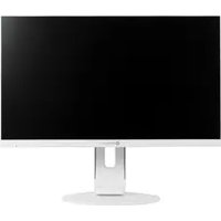
MD-24 - Screen AG Neovo - Free user manual and instructions
Find the device manual for free MD-24 AG Neovo in PDF.


| Product Type | LCD Monitor |
| Screen Size | 23.8" |
| Max. Resolution | FHD 1920 x 1080 |
| Panel Technology | LED-Backlit TFT LCD (IPS Technology) |
| Brightness | 250 cd/m² |
| Contrast Ratio | 20,000,000:1 (DCR) |
| Viewing Angle | 178° / 178° (H/V) |
| Response Time | 5 ms |
| Input Connectors | VGA 15-Pin D-Sub x 1, HDMI 1.4 x 1 |
| Audio | Stereo Audio Jack (3.5 mm) x 1, Internal Speakers 2W x 2 |
| Power Supply | External, DC 12V 2.5A |
| Power Consumption (On Mode) | < 22W |
| Stand Adjustments | Tilt -5° to 23°, Pivot -2.5° to 92.5°, Swivel ±70°, Height 0-110 mm |
| VESA Mounting | 100 x 100 mm |
| Dimensions (with Base) | 540.6 x 498.6 x 249.0 mm |
| Weight (with Base) | 5.7 kg |
| Operating Temperature | 0°C - 40°C |
| Humidity (Operating) | 10% - 85% (non-condensing) |
| Safety & Compliance | FCC Class B, EN60601-1-2, WEEE, Kensington Security Slot |
| Cleaning | Use soft cloth with 50/50 water & isopropyl alcohol; avoid harsh solvents |
| Package Contents | LCD display, stand, screws, power cord, power adapter, D-Sub cable, audio cable, quick start guide, warranty card |
Frequently Asked Questions - MD-24 AG Neovo
User questions about MD-24 AG Neovo
0 question about this device. Answer the ones you know or ask your own.
Ask a new question about this device
Download the instructions for your Screen in PDF format for free! Find your manual MD-24 - AG Neovo and take your electronic device back in hand. On this page are published all the documents necessary for the use of your device. MD-24 by AG Neovo.
USER MANUAL MD-24 AG Neovo
Federal Communications Commission (FCC) Notice (U.S. Only)....4
Waste Electrical and Electronic Equipment-WEEE 5
EMC Information 6
PRECAUTIONS
Notice 9
Cautions When Setting Up 9
Cautions When Using....10
Cleaning and Maintenance....11
Notice for the LCD Display 11
CHAPTER 1: PRODUCT DESCRIPTION
1.1 Package Contents....13
1.2 Installation 14
1.2.1 Installing the Stand....14
1.2.2 Adjusting the Viewing Angle and Height.... 15
1.2.3 Wall Mounting....16
1.3 Control Buttons....17
1.4 Overview ...... 18
1.4.1 Front View 18
1.4.2 Rear View....19
CHAPTER 2: MAKING CONNECTIONS
2.1 Connecting the AC Power 20
2.2 Connecting Input Source Signals 21
2.3 Connecting Audio Devices 22
CHAPTER 3: USING THE LCD DISPLAY
3.1 Turning on the Power 23
3.2 Selecting the Input Source Signal 23
3.3 Adjusting the Volume......24
3.4 Locking the OSD Menu 25
3.5 Using Auto Adjustment Function 25
CHAPTER 4: ON SCREEN DISPLAY MENU
4.1 Using the OSD Menu 26
4.2 OSD Menu Tree 27
CHAPTER 5: ADJUSTING THE LCD DISPLAY
5.1 Luminance Setting....29
5.2 Image Setup Setting....30
5.3 Color Temperature Setting 31
5.4 OSD Setup Setting 32
5.5 Extra Setting....33
TABLE OF CONTENTS
CHAPTER 6: APPENDIX
6.1 Warning Messages....34
6.2 Troubleshooting....35
6.3 Transporting the LCD Display 36
CHAPTER 7: SPECIFICATIONS
7.1 Display Specifications .... 38
7.2 Display Dimensions....39
SAFETY INFORMATION
Federal Communications Commission (FCC) Notice (U.S. Only)

This equipment has been tested and found to comply with the limits for a Class B digital device, pursuant to part 15 of the FCC Rules. These limits are designed to provide reasonable protection against harmful interference in a residential installation. This equipment generates, uses and can radiate radio frequency energy and, if not installed and used in accordance with the instructions, may cause harmful interference to radio communications. However, there is no guarantee that interference will not occur in a particular installation. If this equipment does cause harmful interference to radio or television reception, which can be determined by turning the equipment off and on, the user is encouraged to try to correct the interference by one or more of the following measures:
- Reorient or relocate the receiving antenna.
- Increase the separation between the equipment and receiver.
- Connect the equipment into an outlet on a circuit different from that to which the receiver is connected.
- Consult the dealer or an experienced radio/TV technician for help.

Changes or modifications not expressly approved by the party responsible for compliance could void the user's authority to operate the equipment.
Use only an RF shielded cable that was supplied with the display when connecting this display to a computer device.
To prevent damage which may result in fire or shock hazard, do not expose this appliance to rain or excessive moisture.
THIS CLASS B DIGITAL APPARATUS MEETS ALL REQUIREMENTS OF THE CANADIAN INTERFERENCE-CAUSING EQUIPMENT REGULATIONS.

This device complies with Part 15 of the FCC Rules. Operation is subject to the following two conditions: (1) this device may not cause harmful interference, and (2) this device must accept any interference received, including interference that may cause undesired operation.
Waste Electrical and Electronic Equipment-WEEE
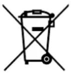

Disposal of Waste Equipment by Users in Private Household in the European Union. This symbol on the product or on its packaging indicates that this product must not be disposed of with your other household waste. Instead, it is your responsibility to dispose of your waste equipment by handing it over to a designated collection point for the recycling of waste electrical and electronic equipment. The separate collection and recycling of your waste equipment at the time of disposal will help to conserve natural resources and ensure that it is recycled in a manner that protects human health and the environment. For more information about where you can drop off your waste equipment for recycling, please contact your local city office your household waste disposal service or the shop where you purchased the product.
EN60601-1-2:2007
| Standard Test Item Standard | ||
| EN60601-1-2:2007 | RAD & CON EN550 | 11(EMI) |
| Harmonic EN61000 | 0-3-2 | |
| Flicker EN61000 | 3-3 | |
| ESD IEC 61000 | 4-2: 2008 | |
| RS IEC 61000 | 4-3: 2006+A1:2007+A2:2010 | |
| EFT IEC 61000 | 4-4: 2012 | |
| Surge IEC 61000 | 4-5: 2005 | |
| CS IEC 61000 | 4-6: 2008 | |
| PFM IEC 61000 | 4-8: 2009 | |
| DIP IEC 61000 | 4-11: 2004 | |
SAFETY INFORMATION
EMC Information
Essential performance of MD-24 and MD-27 is to display images and operate functions normally.
CAUTION
The MD-24 and MD-27 requires special precautions regarding EMC and need to be installed, put into service and used according to the following information.
Do not use any cables other than the cables that provided or specified by us. Using other cables may cause the increase of emission or decrease of immunity.
Do not put any portable and mobile RF communications equipment close to the MD-24 and MD-27. Doing so may affect the MD-24 and MD-27.
The MD-24 and MD-27 should not be used adjacent to or stacked with other equipment. If adjacent or stacked use is necessary, the equipment or system should be observed to verify normal operation in the configuration in which it will be used.
Anyone who connects additional equipment to the signal input part or signal output parts, configuring a medical system, responsible that the system complies with the requirements of IEC/ EN60601-1-2.
| Guidance and manufacturer's declaration – electromagnetic emissions | ||
| The MD-24 and MD-27 is intended for use in the electromagnetic environment specified below. The customer or the user of the MD-24 and MD-27 should assure that it is used in such an environment. Not Life-supporting Medical Equipment. | ||
| Emissions test Compliance | Electromagnetic environment – guidance | |
| Harmonic emissionsIEC/EN61000-3-2 | Class B | The MD-24 and MD-27 is suitable for use in all establishments, including domestic establishments and those directly connected to the public low-voltage power supply network that supplies buildings used for domestic purposes. |
| Voltage fluctuations / flicker emissionsIEC/EN61000-3-3 | Class B | |
SAFETY INFORMATION
| Guidance and manufacturer's declaration – electromagnetic immunity | |||
| The MD-24 and MD-27 is intended for use in the electromagnetic environment specified below. The customer or the user of The MD-24 and MD-27 should assure that it is used in such an environment.Not Life-supporting Medical Equipment. | |||
| Immunity test IEC | EN60601test level | Compliance level E | electromagnetic environment –guidance |
| Electrostaticdischarge (ESD)IEC/EN61000-4-2 | ±6kV contact±8kV air | ±6kV contact±8kV air | Floors should be wood, concrete or ceramic tile. If floors are covered with synthetic material, the relative humidity should be at least 30%. |
| Electrical fast transient / burstIEC/EN61000-4-4 | ±2kV for powersupply lines±1kV for input/output lines | ±2kV for powersupply lines±1kV for input/output lines | Mains power quality should be that of a typical commercial or hospital environment. |
| SurgeIEC/EN61000-4-5 | ±1kV line(s) to line(s)±2kV line(s) to earth | ±1kV line(s) to line(s)±2kV line(s) to earth | Mains power quality should be that of a typical commercial or hospital environment. |
| Voltage fluctuations / flicker emissionsIEC/EN61000-3-3 | <5% UT (>95% dip in UT) for 0.5 cycle40% UT (60% dip in UT) for 5 cycles70% UT (30% dip in UT) for 25 cycles<5% UT (>95% dip in UT) for 5 sec. | <5% UT (>95% dip in UT) for 0.5 cycle40% UT (60% dip in UT) for 5 cycles70% UT (30% dip in UT) for 25 cycles<5% UT (>95% dip in UT) for 5 sec. | Mains power quality should be that of a typical commercial or hospital environment. If the user of the MD-24 and MD-27 requires continued operation during power mains interruptions, it is recommended that the MD-24 and MD-27 be powered from an uninterruptible power supply or a battery. |
| Power frequency(50/60Hz) magnetic fieldIEC/EN61000-4-8 | 3A/m 3A/m | Power frequency magnetic fields should be at levels characteristic of a typical location in a typical commercial or hospital environment. | |
| NOTE: UT is the a.c. mains voltage prior to application of the test level. | |||
Mains power quality should be that of a typical commercial or hospital environment. If the user of the MD-24, MD-27 requires continued operation during power mains interruptions, it is recommended that the MD-24 MD-27 be powered from an uninterruptible power supply or a battery.
ESD declaration statement
There are flicker disturbance on the screen during the test, but auto recover after the test. This permissive loss of performance is specified by the manufacturer, and this phenomena will be put as a clear statement in the User's Manual to avoid misunderstanding.
DIP declaration statement
The EUT power off during the test, but self- recover after the test. This permissive loss of performance is specified by the manufacturer, and this phenomena will be put as a clear statement in the User's Manual to avoid misunderstanding.
SAFETY INFORMATION
| Recommended separation distances between portable and mobile RF communications equipment and the MD-24 and MD-27 | |||
| The MD-24 and MD-27 is intended for use in an electromagnetic environment in which radiated RF disturbances are controlled. The customer or the user of the MD-24 and MD-27 can help prevent electromagnetic interference by maintaining a minimum distance between portable and mobile RF communications equipment (transmitters) and the MD-24 and MD-27 as recommended below, according to the maximum output power of the communications equipment. | |||
| Rated maximum output power of transmitter (W) | Separation distance according to frequency of transmitter (m) | ||
| 150kHz to 80MHzd = 1.2 √P | 80MHz to 800MHzd = 1.2 √P | 800MHz to 2.5GHzd = 2.3 √P | |
| 0.01 0.12 0.12 0.23 | |||
| 0.1 0.38 0.38 0.73 | |||
| 1 1.2 1.2 2.3 | |||
| 10 3.8 3.8 7.3 | |||
| 100 12 12 23 | |||
| For transmitters rated at a maximum output power not listed above, the recommended separation distance “d” in meters (m) can be estimated using the equation applicable to the frequency of the transmitter, where “P” is the maximum output power rating of the transmitter in watts (W) according to the transmitter manufacturer.NOTE 1 At 80 MHz and 800 MHz, the separation distance for the higher frequency range applies.NOTE 2 These guidelines may not apply in all situations. Electromagnetic propagation is affected by absorption and reflection from structures, objects and people. | |||
| Cable length | |
| Power Cord : Accessory 1.8 | m |
PRECAUTIONS
PRECAUTIONS


Symbols used in this manual
 | This icon indicates the existence of a potential hazard that could result in personal injury or damage to the product. |  | ISO 7010-M002: Follow instructions for use |
 | This icon indicates important operating and servicing information. |  | This icon indicates complies with the 93/42/EEC, EN60601-1, EN 60601-1-2 of related European standards. |
Notice
- Read this User Manual carefully before using the LCD display and keep it for future reference.
- The product specifications and other information provided in this User Manual are for reference only. All information is subject to change without notice. Updated content can be downloaded from our web site at displays.agneovo.com.
• To register online, go to displays.agneovo.com. - To protect your rights as a consumer, do not remove any stickers from the LCD display. Doing so may affect the determination of the warranty period.
Cautions When Setting Up
 | Do not place the LCD display near heat sources, such as a heater, exhaust vent, or in direct sunlight. |
 | Do not cover or block the ventilation holes in the housing. |
 | Place the LCD display on a stable area. Do not place the LCD display where it may subject to vibration or shock. |
 | Place the LCD display in a well-ventilated area. |
 | Do not place the LCD display outdoors. |
 | Do not place the LCD display in a dusty or humid environment. |
 | Do not spill liquid or insert sharp objects into the LCD display through the ventilation holes. Doing so may cause accidental fire, electric shock or damage the LCD display. |
Cautions When Using
 | Use only the power cord supplied with the LCD display. |
 | The power outlet should be installed near the LCD display and be easily accessible. |
 | If an extension cord is used with the LCD display, ensure that the total current consumption plugged into the power outlet does not exceed the ampere rating. |
 | Do not allow anything to rest on the power cord. Do not place the LCD display where the power cord may be stepped on. |
 | If the LCD display will not be used for an indefinite period of time, unplug the power cord from the power outlet. |
 | To disconnect the power cord, grasp and pull by the plug head. Do not tug on the cord; doing so may cause fire or electric shock.The mains plug or appliance coupler is used as the disconnect device, the disconnect device shall remain readily operable. Always completely disconnect the power cord set from your product whenever you are working or cleaning on it. Do not make connections while the power is on, because a sudden rush of power can damage sensitive electronic components. |
 | Do not unplug or touch the power cord with wet hands. |


WARNING:
Unplug the power cord from the power outlet and refer to qualified service personnel under the following conditions:
- When the power cord is damaged.
- If the LCD display has been dropped or the housing has been damaged.
- If the LCD display emits smoke or a distinct odor.

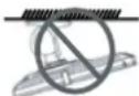
WARNING:
Ceiling mount or mount on any other horizontal surface overhead are not advisable.
Installation in contravention of the instructions may result in undesirable consequences, particularly hurting people and damaging property. Users who have already mounted the display on the ceiling or any other horizontal surface overhead are strongly advised to contact AG Neovo for consultations and solutions to help ensure a most pleasurable and fulfilling display experience.
Cleaning and Maintenance
Disconnect this equipment from any AC outlet before cleaning. Do not use liquid or spray detergents for cleaning. Use a damp cloth. Keeping to clean your monitor by monthly.

Use a soft cloth to clean the LCD display periodically. The screen surface may be cleaned using a soft clean cloth moistened with 50/50 mixture of water and isopropyl alcohol. Never use strong solvents such as thinner, benzene, or abrasive cleaners, since these will damage the cabinet. As a safety precaution, always unplug the monitor before cleaning it.

Do not rub or tap the surface with sharpor abrasive items such as a pen or screwdriver. This may result in scratching the surface.

Do not attempt to service the LCD display yourself, refer to qualified service personnel. Opening or removing the covers may expose you to dangerous voltage or other risks.
Notice for the LCD Display
In order to maintain the stable luminous performance, it is recommended to use low brightness setting.
Due to the lifespan of the lamp, it is normal that the brightness quality of the LCD display may decrease with time.
When static images are displayed for long periods of time, the image may cause an imprint on the LCD display. This is called image retention or burn-in.
To prevent image retention, do any of the following:
- Set the LCD display to turn off after a few minutes of being idle.
- Use a screen saver that has moving graphics or a blank white image.
- Switch desktop backgrounds regularly.
- Adjust the LCD display to low brightness settings.
- Turn off the LCD display when the system is not in use.
Things to do when the LCD display shows image retention:
- Turn off the LCD display for extended periods of time. It can be several hours or several days.
- Use a screen saver and run it for extended periods of time.
- Use a black and white image and run it for extended periods of time.
Notice for the LCD Display
The intended use of the MD-24, MD-27 is to serve as a LCD monitor for integration with the hospital system. It is designed for general purpose for adults using at hospital environment, continuous operation. For displaying and viewing of images for reference. The use of this device does not require any direct contact with patients.
Accessory equipment connected to the analog and digital interfaces must be in compliance with the respective nationally harmonized IEC standards (i.e. IEC 60950 for data processing equipment, IEC 60065 for video equipment, IEC 61010-1 for laboratory equipment, and IEC 60601-1 for medical equipment.) Furthermore all configurations shall comply with the system standard IEC 60601-1-1. Everybody who connects additional equipment to the signal input part or signal output part configures a medical system, and is therefore, responsible that the system complies with the requirements of the system standard IEC 60601-1-1. The unit is for exclusive interconnection with IEC 60601-1 certified equipment in the patient environment and IEC 60XXX certified equipment outside of the patient environment. If in doubt, consult the technical services department or your local representative.
Grounding reliability can only be achieved when the equipment is connected to an equivalent receptacle marked “Hospital Only” or “Hospital Grade”.
Use a power cord that matches the voltage of the power outlet, which has been approved and complies with the safety standard of your particular country.
The single device output analog signals through ADC element (Analog DigitalConvert) conversion to become a digital signal and the video signal is via Video Decorder conversion. It has become the same digital signal, these signals via Scaler IC as zoom in or out action and digital image processing, then through the cable line transmission LVDS signals to one of the LCD module. The last by the clock controller (Timing Controller, TCON), the clock signal is transmitted to the drive IC on the panel and turn on Backlight for LCD module light source by Scaler control.
WARNING: No protection against the ingress of water : IPX0
WARNING: Do not modify this equipment without authorization of the manufacturer. Installation and OSD adjusting should only be carried by manufacturer trained and authorized personnel.
WARNING: To avoid risk of electric shock, this equipment must only be connected to a supply mains with protective earth.
CAUTION: This adapter Manufacturer/model is a forming part of the medical device.
♦ Power by class I power supply.
◆ Adapter manufacturer/model:
ADAPTER TECH: ATM065-P120/ATM065T-P120
Input/output: 100-240V\~50-60Hz, 12V(---) 5A.
EDAC TECH:EM10681G
Input/output: 100-240V\~50-60Hz, 12V(---) 4.16A.
WARNING: Use suitable mounting apparatus to avoid risk of injury.
WARNING: The equipment not suitable for use in the presence of a flammable anesthetic mixture with air or with oxygen or nitrous: Not AP or APG Category
CAUTION: No applied part.
Make sure the user not to contact medical device and the patient at the same time.
CHAPTER 1: PRODUCT DESCRIPTION
1.1 Package Contents
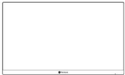
When unpacking, check if the following items are included in the package. If any of them is missing or damaged, contact your dealer.

natural_image
Blank white image with a small icon in the bottom-right corner (no text or symbols)MD-24 MD-27
natural_image
Blank whiteboard with a small logo at the bottom right corner (no text or symbols on the board)LCD display

natural_image
Simple line drawing of a vertical cylindrical object with a flat base and a rectangular top (no text or symbols)


natural_image
Line drawing of a rectangular electronic device with a coiled cable and connector (no text or symbols)Stand Stand screws Power cord Power adapter

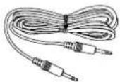


D-Sub (VGA) cable Audio cable Quick start guide Warranty card
Note:
- Use only the supplied power cord and power adapter.
- The above pictures are for reference only. Actual items may vary upon shipment.
PRODUCT DESCRIPTION
1.2 Installation
1.2.1 Installing the Stand
- Place the LCD display with the screen side down on a cushioned surface.
- Attach the stand to the LCD display.
a. Align and attach the stand to the rear of the LCD display.
b. Use the screws to secure the stand.
- Rotate the stand 90° clockwise. Then set the LCD display up in an upright position.

natural_image
Technical illustration of a device's internal components before and after assembly, showing a disassembly or reassembly (no text or symbols present)PRODUCT DESCRIPTION
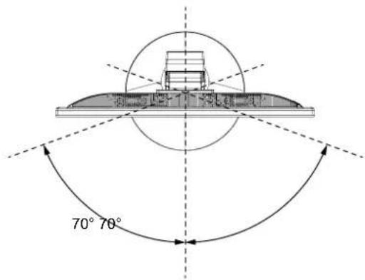
1.2.2 Adjusting the Viewing Angle and Height
For optimal viewing, it is recommended to look at the full face of the screen, then adjust the screen of the LCD display angle and height according to your preference.
Hold the stand so that the screen does not topple when you make the adjustment.
You are able to adjust the screen angle and height as below:
Tilt angle: Pivot angle:


Note: Before making the adjustment, make sure to adjust the height to the highest position, and then tilt the screen 90°.
Swivel angle: Height adjustment:

PRODUCT DESCRIPTION
1.2.3 Wall Mounting
To wall mount the LCD display, do the following steps:
1. Remove the stand.
Please refer to page 36.
2. Wall mount the LCD display.
Screw the mounting bracket to the VESA holes at the rear of the LCD display.

MD-24 MD-27
Note: Take measures to prevent the LCD display from falling down and lessen possible injury and damage
to the display in case of earthquakes or other disasters.
- Use only the 100 x 100 mm wall mount kit recommended by AG Neovo. All AG Neovo wall mount kits comply with VESA standard.
- Secure the LCD display on a solid wall strong enough to bear its weight.
- It is suggested to wall mount the LCD display without tilting it facing downward.

natural_image
Technical diagram showing a mechanical assembly with a ruler and clamp, no visible text or symbols1.3 Control Buttons

1 [+] AUTO/SOURCE/EXIT
- Call out the Source quick menu. Then press the + button repeatedly to switch the input source. Refer to page 23.
- For VGA input signal, press and hold the button to perform auto adjustment. Refer to page 25.
- During OSD menu, close the OSD menu or exit a submenu.
- During volume adjustment or Eco mode selection, close the respective quick menu.
2 [∧] Up
- Call out the Volume quick menu. Then press the / button to adjust the volume level. Refer to page 24.
- For HDMI input signal, you can configure the audio input source. Refer to page 24.
- During OSD menu, scroll through the menu options, select an option, and adjust the settings.
3 [V] Down
- Call out the Eco Mode quick menu. Then press the button to select the desired setting.
- During OSD menu, scroll through the menu options, select an option, and adjust the settings.
4 [MENU/ENTER
- Call out the OSD menu when OSD menu is off.
- During OSD menu, confirm the selection or enter a submenu.
5 [⏻] Power
Turn the LCD display on. Press it again to turn the LCD display off. Refer to page 23.
6 Power indicator
Indicate the operating status of the LCD display:
- Lights blue when the LCD display is turned on.
- Blinks blue when the LCD display is in standby mode.
- Lights off when the LCD display is turned off.
PRODUCT DESCRIPTION
1.4 Overview
1.4.1 Front View

MD-24 MD-27
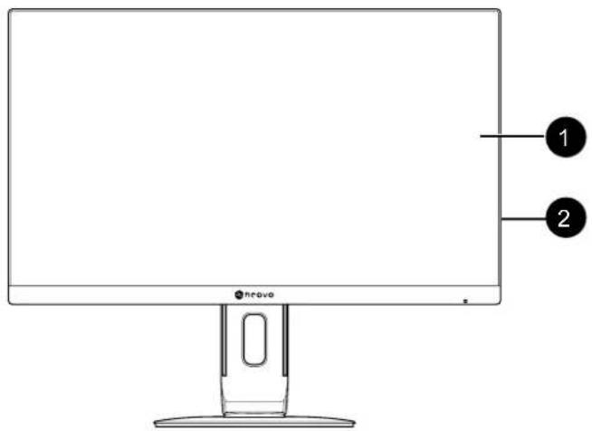
1 Display screen
2 Control buttons
Press the button to perform its function. For more information about each button, refer to page 17.
1.4.2 Rear View
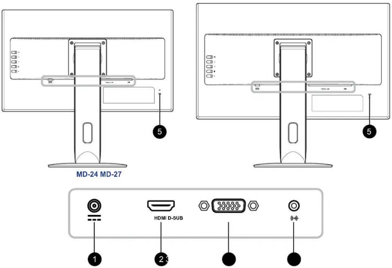
1 DC Power Input
Use to connect the power adapter.
2 HDMI connector
Use to connect an HDMI cable for digital input signal.
3 D-SUB (VGA) connector
Use to connect a D-Sub (VGA) cable for analogue input signal.
4 Audio port
Use to connect an audio cable for audio input.
5 Kensington lock socket
Use to physically lock the system to prevent theft.
The locking device is sold separately. To purchase, contact your retailer.
CHAPTER 2: MAKING CONNECTIONS

CAUTION:
Make sure that the LCD display is not connected to the power outlet before making any connections. Connecting cables while the power is ON may cause possible electric shock or personal injury.
2.1 Connecting the AC Power
- Connect the power cord to the power adapter.
- Connect the power adapter to the DC power input at the rear of the LCD display.
- Connect the power cord plug to a power outlet or a power supply.

natural_image
Pure electrical circuit lines without any symbols
CAUTION:
When unplugging the power cord, hold the power cord by the plug head. Never pull by the cord.
2.2 Connecting Input Source Signals
Input source signals can be connected with either of the following cables:

• VGA
Connect one end of a D-Sub (VGA) cable to the D-SUB (VGA) connector of the LCD display and the other end to the VGA connector of the computer.
• HDMI
Connect one end of an HDMI cable to the HDMI connector of the LCD display and the other end to the HDMI connector of the computer.
MAKING CONNECTIONS
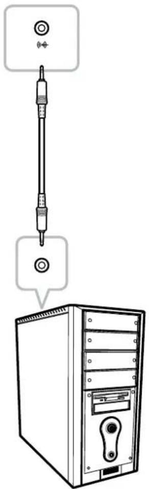
2.3 Connecting Audio Devices
- Connect one end of an audio cable to the audio port at the rear of the LCD display.
- Connect the other end of an audio cable to the audio out port of the computer.
natural_image
Diagram showing a computer tower with a screwdriver inserted, connected to a wall-mounted tower (no text or symbols present)CHAPTER 3: USING THE LCD DISPLAY
3.1 Turning on the Power
- Plug the power cord to a power outlet or power supply.
- Pressthe ⏻ button to turn the LCD display on.

When the LCD display is turned on, press the ⏻ button to turn off the LCD display.
Note: The LCD display still consumes power as long as the power cord is connected to the power outlet. Disconnect the power cord to completely cut off power.
3.2 Selecting the Input Source Signal
- Press the ➕ button to call out the Source quick menu.

- Press the + button repeatedly to switch the input source.
3.3 Adjusting the Volume
- Press the button to call out the Volume quick menu.
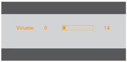
- Press the /or Button to adjust the volume.
Note:
- During volume or menu setting adjustment, press and hold the Button to change the values continuously.
- For HDMI input signal, the Audio Source option will appear on the screen when you press the button.

To configure the audio input source, press the ☐ button to select Audio Source. Then use the ⌘ button to select the desired setting (Line in/Digital).
3.4 Locking the OSD Menu
To lock the OSD menu, press and hold the ⏱ button while the LCD display is off, and then press the ⏻ button to turn the LCD display on.

To unlock the OSD menu, press and hold the ⏻ button while the LCD display is off, and then press the ⏻ button to turn the LCD display on.
3.5 Using Auto Adjustment Function
Press and hold the button to perform auto adjustment. This function automatically tunes the LCD display to its optimal setting, including horizontal position, vertical position, clock, and phase. When auto adjustment is initiated, the below message is displayed on the screen.
Auto Configure Please wait
When the message disappears, this indicates the auto adjustment is completed.
Note:
- During auto adjustment, the screen will slightly shake for a few seconds.
- It is recommended to use the auto adjustment function when using the LCD display for the first time or after a resolution or frequency change.
CHAPTER 4: ON SCREEN DISPLAY MENU
4.1 Using the OSD Menu
- Press the ☐ button to call out the OSD window.

- Press the ∧ or ∨ button to select a menu and press the ⊗ button to enter the selected menu.

The selected menu icon appears on the left panel and the text of the selected menu option turns orange.
- Press the ∧ or ∨ button to select an option and press the ≡ button to enter its submenu.
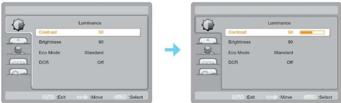
The text of the selected menu option or submenu turns orange.
- Press the /or Button to adjust the settings.
- To exit the submenu, press the + button.
- To close the OSD window, press the + button twice.
Note: When settings are modified, all changes are saved when the user does the following:
• Proceeds to another menu
- Exits the OSD menu
• Waits for the OSD menu to disappear
ON SCREEN DISPLAY MENU
4.2 OSD Menu Tree
| Main Menu Sub menu Reference | |||
Luminance  | Contrast Refer to page 29. | ||
| Brightness | |||
| Eco Mode Text | |||
| Internet | |||
| Game | |||
| Movie | |||
| Sports | |||
| Standard | |||
| DCR Off | |||
| On | |||
Image Setup  | Clock Refer to page 30. | ||
| Phase | |||
| H. Position | |||
| V. Position | |||
| Image Ratio Wide | |||
| 4:3 | |||
Color Temp.  | Color Temp. Warm Refer to page 31. | ||
| Red | |||
| Green | |||
| Blue | |||
ON SCREEN DISPLAY MENU
| Main Menu Submenu Reference | |||
| OSD Setup (OD) | H. Position Refer to page 32. | ||
| V. Position | |||
| Timeout | |||
| Language English | |||
| Spanish | |||
| French | |||
| Portuguese | |||
| Russian | |||
| Simplified Chinese | |||
| Traditional Chinese | |||
| Korean | |||
| Extra (O) | Input Select Auto Refer to page 33. | ||
| HDMI | |||
| D-SUB | |||
| DDC/CI On | |||
| Off | |||
| Reset Yes | |||
| No | |||
| Information | |||
Note: Availability of some menu items depend on the input source signal and current setting. If the menu is not available, it is disabled and grayed out.
CHAPTER 5: ADJUSTING THE LCD DISPLAY
5.1 Luminance Setting
- Press the ☐ button to call out the OSD window.
- Press the ∧ or ∨ button to select and press the button to enter the Luminance menu.


- Press the ∧ or ∨ button to select an option and press the ≡ button to enter its submenu.
| Item Function | Operation Range | ||
| Contrast Adjusts | the difference between the black level and the white level. | Press the ▲ or ▼Mton to adjust the value. | 0 to 100 |
| Brightness Adjusts | the luminance of the screen image. | ||
| Eco Mode | Chooses a predefined picture setting. | Press the ▲ or ▼Mton to select the setting. | Text Internet Game Movie Sports Standard |
| DCR (Dynamic Contrast Ratio) | Activates DCR. This feature provides automatic adjustment of picture brightness and contrast at high speed and dynamic contrast range, such as when watching movies. DCR is suitable for indoor viewing. | On Off |
ADJUSTING THE LCD DISPLAY
5.2 Image Setup Setting
- Press the button to call out the OSD window.
- Press the ∧ or ∨ button to select and press the button to enter the Image Setup menu.


- Press the or button to select an option and press the button to enter its submenu.
| Item Function Operation Range | |||
| Clock Adjusts the | frequency timing to synchronise with the video signal. Note: This menu option is only available if the input source is VGA. | Press the ▲ or ▼ button to adjust the value. | 0 to 100 |
| Phase | Adjusts the phase timing to synchronise with the video signal. Note: This menu option is only available if the input source is VGA. | ||
| H. Position (Horizontal Position) | Moves the screen image to the left or right. Note: This menu option is only available if the input source is VGA. | ||
| V. Position (Vertical Position) | Moves the screen image up or down. Note: This menu option is only available if the input source is VGA. | ||
| Image Ratio | Selects the aspect ratio of the screen image. | Press the ▲ or ▼ button to select the setting. | Wide 4:3 |
| OVER DRIVER* | Enhances the monitor response time. | Press the ▲ or ▼ button on the control panel or the remote control to select the setting. | ON OFF |
*may vary by models
ADJUSTING THE LCD DISPLAY
5.3 Color Temperature Setting
- Press the button to call out the OSD window.
- Press the ∧ or ∨ button to select and press the button to enter the Color Temp. menu.


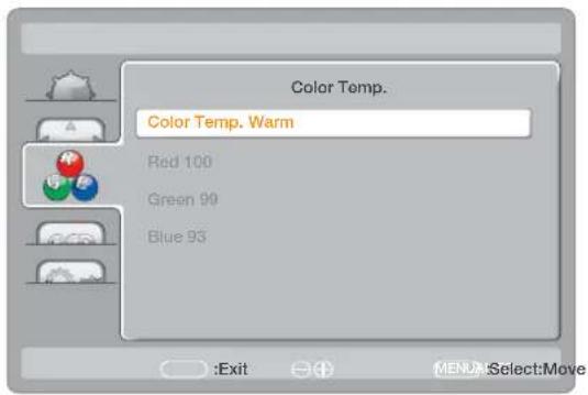
- Press the or button to select an option and press the button to enter its submenu.
| Item Function Operation Range | ||
| Color Temp. (Color Temperature) | Provides several color adjustment settings. | Press the ◀ or ▶ button to select the setting. |
If the Color Temp. setting is set to User, you can customize the color temperature by adjusting the red, green, or blue setting according to your preference. a. Select User and press the 📊button.b. Press the ∧ or ∨ button to select the color you want to adjust. Then press the ≡ button to enter its submenu.c. Press the ∧ or ∨ button to adjust the value (0 ~ 100). a. Select User and press the 📊button.b. Press the ∧ or ∨ button to select the color you want to adjust. Then press the ≡ button to enter its submenu.c. Press the ∧ or ∨ button to adjust the value (0 ~ 100). | ||
ADJUSTING THE LCD DISPLAY
5.4 OSD Setup Setting
- Press the ☐ button to call out the OSD window.
- Press the ∧ or ∨ button to select and press the button to enter the OSD Setup menu.


- Press the or button to select an option and press the button to enter its submenu.
| Item Function Operation Range | |||
| H. Position (Horizontal Position) | Moves the OSD window to the left or right of the screen. | Press theArbutton to adjust the value. | 0 to 100 (increment by 5) |
| V. Position (Vertical Position) | Moves the OSD window up or down the screen. | ||
| Timeout | Sets the length of time (in seconds) the OSD screen is displayed. When the time elapses, the OSD screen is automatically inactivated. | 5 to 100 (increment by 5) | |
| Language | Choose the language used for OSD menus. | Press theArbutton to select the setting. | English Spanish French Portuguese Russian Simplified Chinese Traditional Chinese Korean |
ADJUSTING THE LCD DISPLAY
5.5 Extra Setting
- Press the ☐ button to call out the OSD window.
- Press the ∧ or √ button to select and press the button to enter the Extra menu.

- Press the ∧ or ∨ button to select an option and press the ≡ button to enter its submenu.
| Item Function Operation Range | |||
| Input Select Switches the input source when two input signals are connected. | Press the A or M ton to select the setting. | AutoHDMID-SUB | |
| DDC/CI Activates | the DDC/CI protocol to allow users to configure the monitor by a software using a VGA cable. | OnOff | |
| Reset Resets all | your customized settings to the factory defaults. | YesNo | |
| Information | Displays the information of the input source such as Resolution, Horizontal Frequency, and Vertical Frequency. | - | - |
CHAPTER 6: APPENDIX
6.1 Warning Messages
When any of these warning messages appear, check the following items.
| Warning Message Cause Solution | ||
 | The resolution or the refresh rate of the graphics card of the computer is set too high. | √ Change the resolution or the refresh rate of the graphics card. |
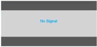 | The LCD display cannot detect the input source signal. | √ Check if the input source is turned ON.√ Check if the signal cable is properly connected.√ Check if any pin inside the cable connector is twisted or broken. |
6.2 Troubleshooting
| Problems Possible | Cause and Solution |
| No picture.·LED indicator is OFF. | ·Check if the LCD display is turned ON.·Check if the power adapter is properly connected to the LCD display.·Check if the power cord is plugged into the power outlet. |
| ·LED indicator is blue.·Check if the computer is turned ON.·Check if the computer is in standby mode, move the mouse or press any key to wake up the computer. | |
| Image position is incorrect. | ·For VGA input, adjust the H. Position and V. Position settings in Image Setup (💡) menu (refer to page 30). |
| The displayed texts are blurry. | ·For VGA input, do the following:√Press and hold the button to auto-adjust the display (refer to page 25).√Adjust the Clock and Phase settings in Image Setup (💡) menu (refer to page 30). |
| Red, blue, green, white dots appear on the screen. | ·There are millions of micro transistors inside the LCD display. It is normal for a few transistors to be damaged and to produce spots. This is acceptable and is not considered a failure. |
| No audio output.·Check if the volume is set to 0 (refer to page 24).·For VGA input, check the audio setting of the computer. | |
| Dew formed on the LCD display. | ·This normally happens when the LCD display is moved from a cold room to a hot room temperature. Do not turn ON the LCD display, wait for the dew condensation to disappear. |
| Faint shadows from a static image appear on the screen. | ·Turn off the LCD display for extended periods of time.·Use a screen saver or a black and white image and run it for extended periods of time. |
APPENDIX
6.3 Transporting the LCD Display
To transport the LCD display for repair or shipment, place the display in its original packaging box.
1. Remove the stand.
a. Place the LCD display with the screen side down on a cushioned surface.
b. Rotate the stand 90^ counter-clockwise. Then remove the screws securing the stand to the LCD display.
c. Remove the stand.

natural_image
Diagram showing a device's internal structure before and after assembly, with no visible text or symbols.- Put the LCD display inside its original plastic. Then place the LCD display with the screen side down on the foam cushion.
- Put all other contents on their designated area (if necessary).
- Close and tape the box.
APPENDIX

natural_image
Technical line drawing showing a 3D mechanical assembly and its open box, with no visible text or symbols.Note:
- It is recommended to use the original packaging box.
- When repacking, carefully place the LCD display in its box and protect the glass panel from touching any object.
CHAPTER 7: SPECIFICATIONS
7.1 Display Specifications
| MD-24 MD-27 | |||
| Panel Panel Type LED | -Backlit TFT LCD (IPS Technology) | LED-Backlit TFT LCD (VA Technology) | |
| Panel Size 23.8" 27.0" | |||
| Max. Resolution FHD 1920 x | 1080 FHD 1920 x 1080 | ||
| Pixel Pitch 0.275 mm 0.311 mm | |||
| Brightness 250 cd/m | 2 | 300 cd/m2 | |
| Contrast Ratio 20,000,000:1 | (DCR) 20,000,000:1 (DCR) | ||
| Viewing Angle (H/V) | 178°/178° | 178°/178° | |
| Display Colour | 16.7M | 16.7M | |
| Response Time | 5 ms | 5 ms | |
| Frequency (H/V) | H Freq. | 30 kHz-85 kHz | 30 kHz-85 kHz |
| V Freq. | 45 Hz-76 Hz | 45 Hz-76 Hz | |
| Input VGA 15-Pin D-Sub x 1 | 15-Pin D-Sub x 1 | ||
| HDMI | 1.4 x 1 | ||
| Audio | Audio In | Stereo Audio Jack (3.5 mm) x 1 | Stereo Audio Jack (3.5 mm) x 1 |
| Internal Speakers | 2W x 2 | 2W x 2 | |
| Power | Power Supply | External | External |
| Power Requirements | DC 12V, 2.5A | DC 12V, 2.5A | |
| On Mode | < 22W (On) | < 25W (On) | |
| Stand-by Mode | < 0.5W | < 0.5W | |
| Off Mode | < 0.5W | < 0.5W | |
| Operating Conditions | Temperature | 0°C-40°C (32°F-104°F) | 0°C-40°C (32°F-104°F) |
| Humidity | 10%-85% (non-condensing) | 10%-85% (non-condensing) | |
| Storage Conditions | Temperature | -25°C-55°C (-13°F-131°F) | -25°C-55°C (-13°F-131°F) |
| Humidity | 5%-93% (non-condensing) | 5%-93% (non-condensing) | |
| Mounting | VESA FPMPMI | Yes (100 x 100 mm) | Yes (100 x 100 mm) |
| Stand | Tilt | -5° to 23° | -5° to 23° |
| Pivot | -2.5° to 92.5° | -2.5° to 92.5° | |
| Swivel | ± 70° | ± 70° | |
| Height Adjustment | 0-110 mm | 0-110 mm | |
| Security | Kensington Security Slot | Yes | Yes |
| Dimensions | Product with Base(W x H x D) | 540.6 x 498.6 x 249.0 mm(21.3" x 19.6" x 9.8") | 611.9 x 518.7 x 249.0 mm(24.1" x 20.4" x 9.8") |
| Packaging(W x H x D) | 632.0 x 417.0 x 282.0 mm(24.9" x 16.4" x 11.1") | 715.0 x 450.0 x 305.0 mm(28.1" x 17.7" x 12.0") | |
| Weight | Product with Base | 5.7 kg (12.5 lb) | 6.6 kg (14.5 lb) |
| Packaging 7.8 kg (17.1 lb) | 8.9 kg (19.6 lb) | ||
Note:
All specifications are subject to change without prior notice.
7.2 Display Dimensions
MD-24

MD-27

AG Neovo
Company Address: 5F-1, No. 3-1, Park Street, Nangang District, Taipei, 11503, Taiwan.

- PRECAUTIONS
- CHAPTER 1: PRODUCT DESCRIPTION
- CHAPTER 2: MAKING CONNECTIONS
- CHAPTER 3: USING THE LCD DISPLAY
- CHAPTER 4: ON SCREEN DISPLAY MENU
- CHAPTER 5: ADJUSTING THE LCD DISPLAY
- TABLE OF CONTENTS
- CHAPTER 6: APPENDIX
- CHAPTER 7: SPECIFICATIONS
- SAFETY INFORMATION
- Federal Communications Commission (FCC) Notice (U.S. Only)
- Waste Electrical and Electronic Equipment-WEEE
- EMC Information
- CAUTION
- ESD declaration statement
- DIP declaration statement
- Notice
- WARNING:
- Cleaning and Maintenance
- Notice for the LCD Display
- Package Contents
- Note:
- PRODUCT DESCRIPTION
- Installation
- Installing the Stand
- Adjusting the Viewing Angle and Height
- Wall Mounting
- Remove the stand.
- Wall mount the LCD display.
- Control Buttons
- [+] AUTO/SOURCE/EXIT
- [∧] Up
- [V] Down
- [MENU/ENTER
- [⏻] Power
- Power indicator
- Overview
- Front View
- Rear View
- DC Power Input
- HDMI connector
- D-SUB (VGA) connector
- Audio port
- Kensington lock socket
- CAUTION:
- Connecting the AC Power
- Connecting Input Source Signals
- • VGA
- • HDMI
- MAKING CONNECTIONS
- Connecting Audio Devices
- Turning on the Power
- Selecting the Input Source Signal
- Adjusting the Volume
- Locking the OSD Menu
- Using Auto Adjustment Function
- Using the OSD Menu
- ON SCREEN DISPLAY MENU
- OSD Menu Tree
- Luminance Setting
- ADJUSTING THE LCD DISPLAY
- Image Setup Setting
- Color Temperature Setting
- OSD Setup Setting
- Extra Setting
- Warning Messages
- Troubleshooting
- APPENDIX
- Transporting the LCD Display
- Display Specifications
- Display Dimensions
Brand : AG Neovo
Model : MD-24
Category : Screen