
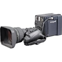
ICD-49 - Camera Ikegami - Free user manual and instructions
Find the device manual for free ICD-49 Ikegami in PDF.


| Product type | Black and white surveillance camera |
| Brand | Ikegami |
| Model | ICD-49 |
| Sensor | 1/2 inch CCD, interline transfer type |
| Effective pixels | 752 (H) × 582 (V), approx. 440,000 pixels |
| Horizontal resolution | 560 lines |
| Minimum illumination | 0.01 lux (F1.4, halogen lamp 2856K) |
| Signal-to-noise ratio | 50 dB or more (AGC off, DETAILS off) |
| Scanning system | 2:1 interlace, 625 lines/50 Hz (CCIR) |
| Synchronization | INT, line lock, GENLOCK (VBS/VS/BBS) |
| Video output | 1.0 Vp-p / 75 Ω, BNC connector |
| Lens mount | CS mount (C mount adapter supplied) |
| Functions | AES, electronic shutter 1/50 ~ 1/100000 s, BLC (ON/OFF/SPOT), AGC (LOW/MID/HIGH/HYP-AGC), camera identification (16 characters), OSD, RS-485 |
| Power supply | 24 V AC ±10% 50 Hz / 12 V DC (10.5 ~ 15 V) or 230 V AC ±10% 50 Hz |
| Power consumption | Approx. 310 mA (24 V AC), 320 mA (12 V DC), 30 mA (230 V AC) |
| Dimensions (W × H × D) | 62 × 55 × 118 mm (excluding protrusions) |
| Weight | Approx. 430 g (24 V AC/12 V DC), 860 g (230 V AC) |
| Operating temperature | -10 °C to +50 °C, humidity ≤90% non-condensing |
| Connectors | Video output BNC, GENLOCK input BNC, lens 4-pin, RS-485 5-pin terminal block, power supply 2-pin terminal block |
| Supplied accessories | Instruction manual, C mount adapter, lens connector plug |
Frequently Asked Questions - ICD-49 Ikegami
User questions about ICD-49 Ikegami
0 question about this device. Answer the ones you know or ask your own.
Ask a new question about this device
Download the instructions for your Camera in PDF format for free! Find your manual ICD-49 - Ikegami and take your electronic device back in hand. On this page are published all the documents necessary for the use of your device. ICD-49 by Ikegami.
USER MANUAL ICD-49 Ikegami
WARNING — TO PREVENT FIRE OR ELECTRIC SHOCK, DO NOT
EXPOSED THIS APPLIANCE TO
RAIN OR MOISTURE.
Ikegami
Ikegami Tsushinki Co., Ltd.
Thank you very much for your wise choice of the Ikegami B/W Camera. Please carefully read this Instruction Manual to keep your camera at full capacity.
Contents
Page
- Handling precautions ...... E-1
- General E-1
- Features ...... E-1
- Names of Parts and their functions ...... E-2
- Setting E-5
5-1. User setting E-5
5-2. Setting switches and their functions ...... E-5
5-3. User setting menus ...... E-5
- Communication Command ...... E-6
6-1. Communicating conditions ...... E-6
6-2. Command format ...... E-6
6-3. Communication flow E-7
6-4. Communication command ...... E-8
6-5. Table of OSD display character codes ...... E-9
- Specifications ...... E-10
- Warranty and after-sale service ...... E-12
- Appearance View
- Setup Menu
Instructions for Disposal of Electric and Electronic Equipment in Private Household

natural_image
Symbol of a trash bin crossed out by two diagonal lines (no text or numbers present)Disposal of used Electric and Electronic Equipment (Applicable in the European Union and other European countries with separate collection systems)
This symbol on the product, or in the related documents in the package, indicates that this product shall not be treated as normal household waste. Instead, it should be taken to a proper applicable collection point or depot for the recycling of electric and electronic equipment.
By ensuring this product is disposed of correctly, you will help prevent possible negative consequences for the environment and human health, which could otherwise be caused by inappropriate waste handling of this product. The recycling of materials will help to conserve natural resources.
For more detailed information about recycling of this product, please contact your local city authority, your household waste disposal service or the place where you purchased the product.
1. Handling precautions
(1) Do not open the case of camera and never touch inside, where precision parts are assembled. A trouble or accident may result.
(2) Do not install the unit where it is exposed to water splash, high humidity and heavy dust. Internal parts may be damaged.
(3) Be very careful not to drop or shock the camera.
(4) Never touch the CCD surface.
2. General
This is a B/W camera of high sensitivity, high resolution and high picture quality using a 1/2 inch CCD having high sensitivity to near-infrared ray.
It has a high resolution of 560 horizontal lines (CCIR), minimum illumination of 0.01 lux, and a smear level of -120 dB, and is equipped with such functions as line lock, automatic electronic shutter, backlight compensation, two-way automatic iris, etc. It is a high utility video camera for monitoring the outdoor scene and as a night-vision camera in combination with near-infrared ray projector.
Moreover, since it is endowed with OSD and RS-485 communicating function, a high-grade monitor system architecture is also possible.
3. Features
(1) Compactness
(2) High sensitivity and high resolution
(3) High sensitivity to near-infrared ray
(4) Reduced smear
(5) Backlight compensation (BLC)
(6) Two-way auto iris function
(7) Line lock
(8) AES (Automatic Electronic Shutter)
(9) Flange focal distance adjustment
(10) RS-485 communicating function
4. Names of parts and their functions
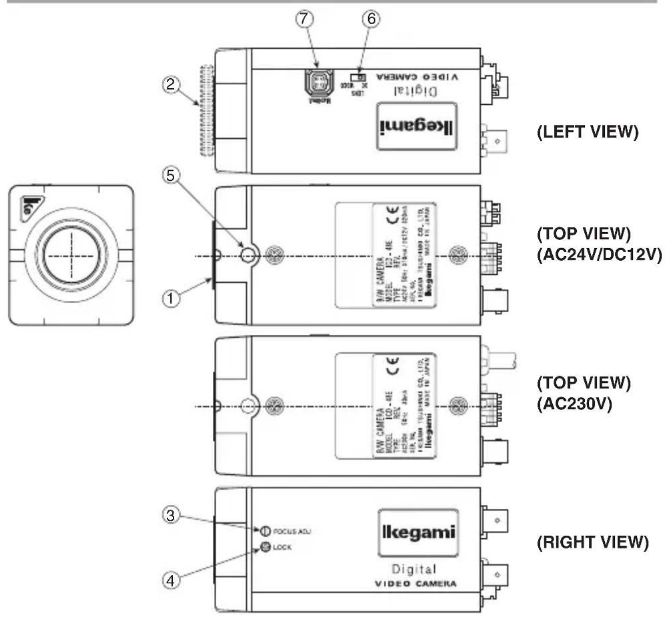
(BACK VIEW)
① Lens mount (CS mount)
Accepts many types of CS mount lenses.
② C mount adaptor (Accessory)
Attached to the lens mount to accept many types of C mount lenses.
③ Flange focal distance adjuster
Used to adjust the flange focal distance depending on the type of lens used. Helpful when the lens' focus ring fails to put into focus.
④ Flange focal distance lock screw
Used to mechanically lock the flange focal distance after fine adjustment of it.
⑤ Holder screw hole
Used to mount the camera onto the camera holder. Effective for general camera tripods.
Note: Be sure to use less than 5.5mm- long setscrew (1/4" – 20 UNC) for mounting the camera to tripods or holder.
⑥ Lens selector switch
Used to choose between the video iris and the DC iris depending on the type of auto iris lens used.
⑦ Auto iris lens connector
Specifically used to connect the auto iris lens. Use the connector plug that is attached to the camera.
- For the video type auto iris lens
Set the lens selector switch to VIDEO position.
— Connector cable leads —
- Red (power)
- Not used
- White (video)
- Black (shielded)
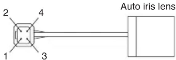
* Dress the tip of the green lead to prevent a short-circuit.
- For the DC type auto iris lens
Set the lens selector switch to DC position.
— Connector cable leads —
- Damping coil (-)
- Damping coil (+)
- Driving coil (+)
- Driving coil (-)
* Connect the leads as shown above.
Refer also to the instructions of the lens.
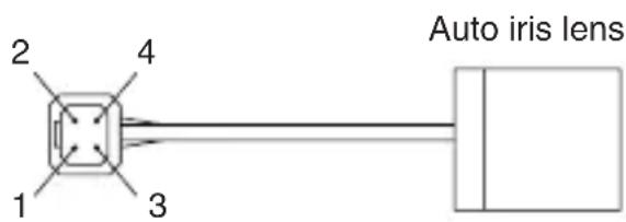
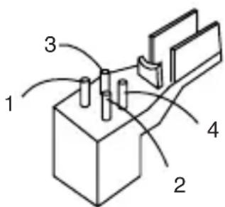
Numbers of connector pins
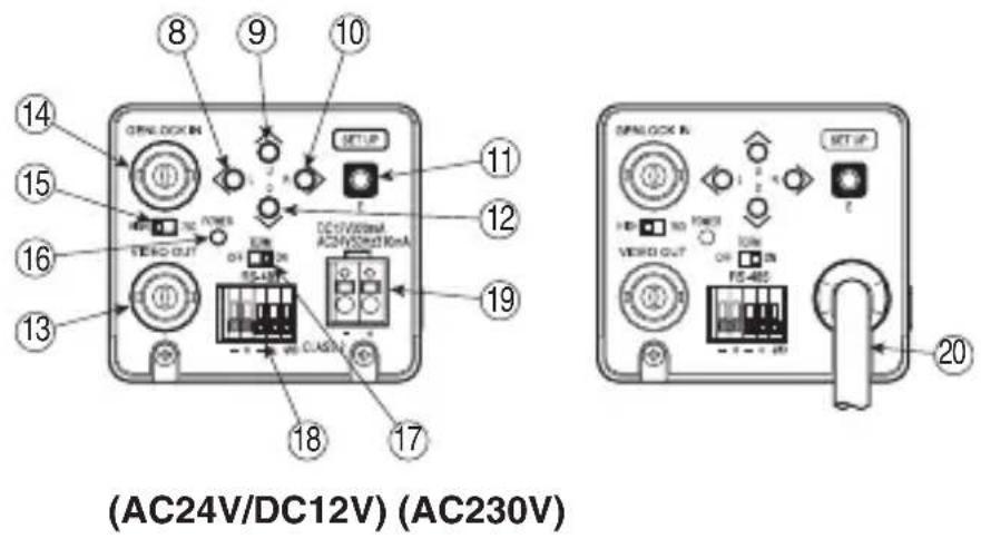
⑧ - ⑫ Camera setting function switches
Use them by referring to each operation item.
⑬ Video output terminal
Used to give out the video signal. Connect this to the video input terminal of a monitor, switcher etc. (To be terminated with 75-ohm impedance.)
⑭ External sync signal input terminal
Used to receive the GENLOCK (general lock) signal. For external synchronization, input VBS or BBS signal.
⑮ External sync signal 75-ohm termination switch
Set to HIGH position when the GENLOCK signal is looped with T-shaped connector. Usually, set at 75-OHM position.
⑯ Power indicator
Green LED lights up when power is supplied to the camera.
⑰ Terminal switch for RS-485
In RS-485 communication control, turn this switch to ON side for one-to-one control, and turn it to OFF side for daisy-chain connection. (For use in daisy-chain connection, turn ON the terminal switch by terminal connection equipment.)
⑱ RS-485 connection terminal block
Used for RS-485 connection.
⑲ AC24V/DC12V power input terminal
Input the power of AC21.6\~26.4V or DC10.5\~15V.
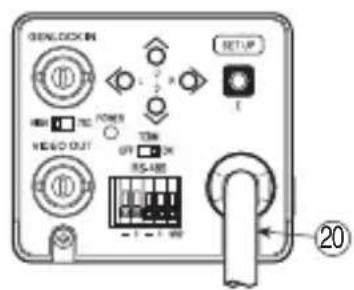
⑳ AC 230V power cable
Used to supply AC 230V power. AC 196-264V is acceptable.
Note: The camera has no power switch. Just plug in the power cable and the camera gets started. To turn off the camera, just unplug the cable.
The socket-outlet shall be installed near the equipment and shall be easily accessible.
5. Setting
5-1. User setting
On this camera, user can make settings of picture quality, synchronization, identification etc. by himself or herself.
The setup menu is formed in a tree view, and the picture sharpness, synchronization, ID and others can be set up by on-screen characters. (See the setup tree given in the end of this manual.)
5-2. Setting switches and their functions
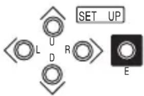
On the back of the camera there are the pushbutton switches and display as shown at the left.
UP switch (U): Setting item selection (up)
DOWN switch (D): Setting item selection (down)
RIGHT switch (R): Setting change and setting item selection (right)
LEFT switch (L): Setting change and setting item selection (left)
ENTER (E): Setting mode call on/off, setting entry
* To enter into the setup mode, keep pressing the E button.
5-3. User setting menus
(1) CAMERA ID Up to 16 characters can be accepted and displayed.
Switching on and off the CAMERA ID function and presetting ID code characters.
(2)SHUTTER Setting of high-speed electronic shutter
Selection of high-speed shutter, display of the screen at VARIABLE mode
(3)LIGHT CONT. Selection of AES or auto iris lens
Setting of back-light compensation as sub-menu
(4)GAIN Selection of AGC, HYP-AGC and fix
(5)SYNC Selection of synchronization system (INT, LL)
(It is impossible to select LL when the power is not synchronous.)
GENLOCK is selected automatically.
(GENLOCK is not displayed without external sync signal.)
It is possible to adjust the phase on sub-menu.
(6)MENU LOCK Setting procedure is locked. (Unlocking: U→R→D→L→U→D→E)
- Setting Indications and functions common on the setting menu
(1) EXIT Ending (Saving) the setting mode and returning to the regular display.
(2)CANCEL Recalling the previously saved settings.
(3)RESET Recalling the factory-settings.
(4)RET Returning to the preceding setting menu.
Select one of these indications and press the E switch.
6. Communication Command
6-1. Communicating conditions
(1) Baud rate : 9600 bps
(2) Data length : 8 bits
(3) Parity : None
(4) Stop bit : 1 bit
6-2. Command format
| 1 | SOH (01h) |
| 2 | Receiving model ID *1 |
| 3 | Receiving sub ID *2 |
| 4 | T ransmitting model ID *3 |
| 5 | Optional bit function *4 |
| 6 | T ransmitting sub ID *5 |
| 7 | Reservation (80 h) |
| 8 | STX (02h) |
| 9 | Command (Variable length) |
| n | |
| n+1 | ETX (03h) |
| n+2 | BCC (Exclusive-OR of receiving model ID to ETX) |
4th to 7th bytes can be omitted.
To the commands omitted of transmitting ID and transmitting sub ID, response is given from camera in the setting as follow:
Transmitting model ID omitted → No response from camera
Transmitting sub ID omitted → Response is given from camera by transmitting sub ID = 30 h.
*1 Transmitting model ID ICD-48E...43h
*2 Transmitting sub ID ICD-48E...Camera No. + 30h (30h \~ FFh)
Set the camera No. by "RS-485 ID" items in the special menu for setup. Camera can not be operated unless the settings of "Transmitting sub ID" and "RS-485 ID" are identical.
Ex. Camera No. 1 = 31h
Camera No. 15 = 3Fh
*3 Transmitting model ID Set the transmitting model ID. (20h \~ 7Dh) Keyboard ID (2Dh) etc.
*4 Optional bit function
| Bit Settings |
| 7 Regular 1 |
| 6 Backup |
| 5 Backup |
| 4 Backup |
| 3 Backup |
| 2 Backup |
| 1 Backup |
| 0 Request for ACK/NAK response (0: No, 1: Yes) |
*5 Transmitting sub ID Set the transmitting sub ID. (30h \~ FFh)
6-3. Communication flow
Operating machine ICD-48E
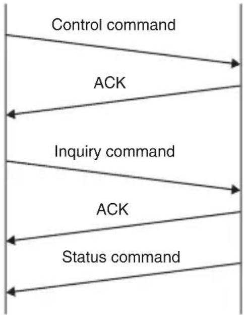
flowchart
graph TD
    A["Control command"] --> B["ACK"]
    B --> C["Inquiry command"]
    C --> D["ACK"]
    D --> E["Status command"]
6-4. Communication command
| Command | Function Remarks | ||||||
| 1 | 2 | 3 | 4 | 5 | 6 | ||
| a | ? | Inquiries by type of camera | *1 | ||||
| b D | at Camera | ID display ON/OFF(0:Off, 1:On) | |||||
| c | x | 1 | x 2 y | 1 | Setting of camera ID display positionxx: Horizontal position (09 ~ 3Fh)yy: Vertical position (09 h ~ 3Dh) | ||
| d | Pos Str1 Str2 Str3 Str4 | Setting of camera ID display charactersPos: Setting head character position(0h ~ Fh)Str: Character code (20h ~ FFh) | Character code can be designated up to maximum 16 characters. | ||||
| g D | at Setting high-speed shutter speed0:Off, 1:1/60, 2:1/125, 3:250, 4:1/500,5:1/1000, 6:1/2000, 7:1/4000, 8:1/10000,9:Variable, A:1/100000 | ||||||
| h D | at LENS/AES mode (0:LENS, 1:AES) | ||||||
| i Dat Setting of backlight compensation mode(0:Off, 1:On, 2:SPOT) | |||||||
| j | Dat1 Dat2 | Setting of backlight compensation level(40h~BFh) | |||||
| l Dat Gain setting | 0:LOW, 1:MID, 2:HIGH,3:AGC, 4:HYP-AGC | ||||||
| o Dat Sync. mode setting (0:INT, 1:LL) | |||||||
| p | Cor Fin1 Fin2 | V-phase setting in LL modeCor: LL COARSE(0:0°, 1:90°, 2:180°, 3:270°)Fin: LL FINE (00h ~ FFh) | |||||
| q | Pha1 Pha2 | Setting gain lock H-phase (00h~FFh) | |||||
| u | Dat1 Dat2 | Detail level setting (00h~0Fh) | |||||
| v | Dat1 Dat2 | Pedestal level setting (00h~0Fh) | |||||
| w | Sw Lock | Setting of camera body switch input permission/prohibitionSw: Switch input (0: prohibit, 1: permit)Lock: Setup lock (0: OFF, 1: ON) | |||||
| x Dat Storage cancellation and resetting of setting(0: store, 1: cancel, 2: reset) | |||||||
| ? | Cod | Inquiry of setting status | *2 | ||||
| 80 | Dat1 Dat2 Dat3 | Variable shutter speed setting000h (1/50) ~ 1FFh (1/100000) | |||||
| 82 | Dat1 Dat2 | DC iris level setting (00h~1Fh) | |||||
| 83 x1 x2 y1 y2 | Setting of spot photometric area coordinatesxx: abscissa informationyy: ordinate information | *3 | |||||
Blank : Space or omittable
*1 Information of the type and software version of camera and is given.
Ex. Inquiry about the type and version of camera for ICD-48E Version 1.00A a? → ICD-48PV1.00A
*2 Response to the inquiry about the setting status is given in the format identical to that of each setup expansion command.
Ex. Inquiry about the setting of high-speed shutter speed in OFF setting ? g → g0
*3 Spot photometric area coordinates is designated by information of the following settings.
However, these settings should be in such combination that the ordinate and abscissa the right end and the bottom should be maximum within Fh.
x1 : Ordinate at left end in photometric area (0 \~ Fh)
x2 : Width of photometric area (0 \~ Fh)
y1 : Abscissa at the top in photometric area (0 \~ Fh)
y2 : Height of in photometric area (0 \~ Fh)
6-5. Table of OSD display character codes
| 0 | 1 | 2 | 3 | 4 | 5 | 6 | 7 | |
| 0 | S | P | ||||||
| 1 | ! | 1 | ||||||
| 2 | “ | 2 | ||||||
| 3 | # | 3 | ||||||
| 4 | $ | 4 | ||||||
| 5 | % | 5 | ||||||
| 6 | & | 6 | ||||||
| 7 | ‘ | 7 | ||||||
| 8 | ( | 8 | ||||||
| 9 | ) | 9 | ||||||
| A | * | : | J | Z | j | z | ||
| B | + | ↑ | K | ↑ | ||||
| C | → | , | ← | L | ¥ | l | ↘ | |
| D | ← | - | ↓ | M | ] | m | ↙ | |
| E | ↑ | . | → | N | ^ | n | ↖ | |
| F | ↓ | / | O | _ | o |
0
7. Specifications
(1) Imaging device: 1/2 inch, IT-CCD
(2) Effective pixels: 752(H) x 582(V), about 440,000 pixels
(3) Scanning system: 2:1 interlace, as per CCIR system
(4) Scanning system: 625 lines at 50 Hz
(5) Synchronization system: INT, LINE LOCK, GENLOCK
(6) GENLOCK input: VBS or VS; 1.0 Vp-p/75 ohms (High impedance selectable)
BBS; 0.45 Vp-p/75 ohms (High impedance selectable)
(7) Video output: VS; 1.0 Vp-p/75 ohms
(8) Horizontal resolution: 560 TV lines
(9) S/N ratio: 50 dB/rms or more
(AGC OFF, DETAIL OFF, weighting ON)
(10) Minimum illumination: 0.01 lux/F1.4 (AGC ON)
(Color temp.: 2856K, Light source: Halogen lamp)
(11) Backlight compensation function: ON/OFF switchable
(12) AES function: ON/OFF switchable
(AES range: About 1 : 2000)
(13) High-speed electronic shutter: Make selection among 1/50\~1/100,000 sec., 9-STEP and VARIABLE.
In the case of "VARIABLE", it can be set within the range of 1/50\~1/100,000 sec.
(14) AGC (Automatic gain control): ON (AGC, HYPER AGC)/OFF (LOW, MID, HIGH) switchable
(15) Auto iris function: Compatible with video iris and DC iris (selectable) (With DC iris level adjuster)
(16) Camera ID function: Provided (One line, 16 characters)
(17) Local setting functions: Selectable and adjustable with on-screen display using 5 control buttons; Camera ID, AES/electronic shutter, BLC ON/OFF/SPOT selection and level adjustment, DC iris level, INT/LL, external sync frequency phase adjustment, DETAIL level, AGC ON/OFF, PED. level, menu lock selectable.
(18) RS-485 communicating function: Provided
Control item:
Settable items include local setup function and RS-485 function ID.
(19) Lens mount: CS/C mount (with C mount adaptor)
(20) Flange focal distance adjuster: Provided
(21) Power supply: AC 24V ±10%, 50 Hz/ DC 12V (10.5-15V)
AC 230V ±15%, 50 Hz
(22) Power consumption: AC230V: Approx. 30mA
AC24V: Approx. 310mA
DC12V: Approx. 320mA
(23) Ambient temp./humidity -10°C to +50°C/Within 30\~90%RH
for operation: (No dew condensation)
(24) Camera mount: 1/4"-20UNC
(Attachable on top and bottom.)
(25) External dimensions: 62(W) x 55(H) x 118(D) mm (No projections included)
(W x H x D)
(26) Weight: AC24V/DC12V: Approx. 430 g
AC230V: Approx. 860 g
(27) I/O connectors: • VIDEO OUT: BNC
• GENLOCK IN: BNC
- LENS: 4-pin
(Applicable plug: E4-191J-150 or equivalent)
• RS-485 communicating: 5 pin push-in terminal
• AC 24V/DC 12V input: 2 pin push-in terminal
(28) Accessories: • Instruction manual 1
- C mount adaptor 1
- Lens connector plug 1
(E4-191J-150 or equivalent)
* The specifications and appearance may be subject to change without prior notice.
8. Warranty and after-sale service
A warranty accompanies this product. Read and fill out the warranty card that you have received at your dealer. Keep this card in a safe place.
- Please consult Ikegami Electronics (Europe) GmbH or your dealer for full warranty information. Your dealer will repair or replace free of charge within the warranty period according to the warranty coverage.
- For repairs after the expiration of the warranty period, consult your dealer or sales representative. It will first be judged whether the trouble is repairable or not. Charged servicing will then be made upon the request of user.
- Before you ask for servicing, take trouble of reading the Instruction Manual. If the unit still fails, take note of the model number, date of purchase, problem etc. in detail, and inform your dealer or sales representative.
- If you have questions about the after-sale service, contact your dealer or sales representative.
* We suggest you ask for preventive inspection earlier.
natural_image
Simple line drawing of a trash bin with two crossed lines indicating no waste or prohibition (no text or symbols)Used to give out the video signal. Connect this to the video input terminal of a monitor, switcher etc. (To be terminated with 75-ohm impedance.)
natural_image
Symbol of a trash bin crossed out by two diagonal lines (no text or numbers present)* The specifications and appearance may be subject to change without prior notice.
natural_image
Symbol of a trash bin crossed out by two crossed lines (no text or numbers present)(CA 24 V/CC 12 V)
(230 V CA)
37 Brook Avenue, Maywood, New Jersey 07607, U.S.A.
Phone: (201) 368-9171, FAX 201-569-1626
Ikegami Electronics (Europe) GmbH
Ikegami Strasse 1, 41460 Neuss 1, F.R. Germany
TEL. 02131-123-0/FAX 02131-102820
■ Ikegami Electronics (Europe) GmbH U.K. Branch
Unit E1 Cologne Court Brooklands Close,
Windmill Road Sunbury-on-Thames Middlesex TW16 7EB, UK
TEL. 01932-769700/FAX 01-92-769710
- Contents
- Instructions for Disposal of Electric and Electronic Equipment in Private Household
- Disposal of used Electric and Electronic Equipment (Applicable in the European Union and other European countries with separate collection systems)
- Handling precautions
- General
- Features
- Names of parts and their functions
- Setting
- 5-1. User setting
- 5-2. Setting switches and their functions
- 5-3. User setting menus
- Communication Command
- 6-1. Communicating conditions
- 6-2. Command format
- 6-3. Communication flow
- Specifications
- Warranty and after-sale service
Brand : Ikegami
Model : ICD-49
Category : Camera