CP 2048 - Remote control RGBlink - Free user manual and instructions
Find the device manual for free CP 2048 RGBlink in PDF.


User questions about CP 2048 RGBlink
0 question about this device. Answer the ones you know or ask your own.
Ask a new question about this device
Download the instructions for your Remote control in PDF format for free! Find your manual CP 2048 - RGBlink and take your electronic device back in hand. On this page are published all the documents necessary for the use of your device. CP 2048 by RGBlink.
USER MANUAL CP 2048 RGBlink
natural_image
Front view of a control panel with buttons, a display screen, and a rotary knob (no visible text or symbols)USER MANUAL
RGBlink
Arcle No: RGB-RD-UM-CP 2048 E001 Revision No: V1.0
CONTENTS
CONTENTS 2
Declaraons 3
FCC/Warranty 3
Operators Safety Summary 4
Installaon Safety Summary......4
Chapter 1 Your Product....6
1.1 In the Box....6
1.2 Product Overview....7
1.2.1 Back Panel 8
1.2.2 Top Panel 9
1.2.3 Dimension 13
Chapter 2 Using Your Product....14
2.1 CP 2048 Control VENUS X3....14
2.1.1 Connection 14
2.1.2 Select Output Port 15
2.1.3 Size&Posion 16
2.1.4 Add Layer 17
2.1.5 Save&Load 18
2.1.6 Logo Capture & Load 19
2.1.7 EDID Management 20
2.1.8 System Mode....21
2.2 CP 2048 Control VSP 5360....24
2.2.1 Connection 24
2.2.2 Edit the Input Signal 25
2.2.3 Output Resoluon Setng 26
2.2.4 Switch the Signal 26
2.2.5 Scale 27
2.2.6 Logo Capture & Load 27
2.2.7 Save&Load 28
2.2.8 EDID Management 30
2.2.9 System Mode....31
Chapter 3 Ordering Codes .... 34
3.1 Product 34
Chapter 4 Contact Us....35
Chapter 5 Appendix....36
5.1 Terms & Denions 36
5.2 Revision History....41
Thank you for choosing our product!
This User Manual is designed to show you how to use this video processor quickly and make use of all the features. Please read all direcons and instrucons carefully before using this product.
Declarations
FCC/Warranty
Federal Communicaons Commission (FCC) Statement
This equipment has been tested and found to comply with the limits for a class A digital device, pursuant to Part 15 of the FCC rules. These limits are designed to provide reasonable protecon against harmful interference when the equipment is operated in a commercial environment. This equipment generates, uses, and can radiate radio frequency energy and, if not installed and used in accordance with the instrucon manual, may cause harmful interference to radio communicaons. Operaon of this equipment in a residential area may cause harmful interference, in which case the user will be responsible for correcng any interference.
Guarantee and Compensaon
RGBlink provides a guarantee relang to perfect manufacturing as part of the legally spulated terms of guarantee. On receipt, the purchaser must immediately inspect all delivered goods for damage incurred during transport, as well as for material and manufacturing faults. RGBlink must be informed immediately in wring of any complains.
The period of guarantee begins on the date of transfer of risks, in the case of special systems and soware on the date of commissioning, at latest 30 days aer the transfer of risks. In the event of jused noce of compliant, RGBlink can repair the fault or provide a replacement at its own discretion within an appropriate period. If this measure proves to be impossible or unsuccessful, the purchaser can demand a reducon in the purchase price or cancellaon of the contract. All other claims, in parcular those relang to compensaon for direct or indirect damage, and also damage aributed to the operaon of soware as well as to other service provided by RGBlink, being a component of the system or independent service, will be deemed invalid provided the damage is not proven to be aributed to the absence of properes guaranteed in wring or due to the intent or gross negligence or part of RGBlink. If the purchaser or a third party carries out modicaons or repairs on goods delivered by RGBlink, or if the goods are handled incorrectly, in parcular if the systems are commissioned operated incorrectly or if, aer the transfer of risks, the goods are subject to inuences not agreed upon in the contract, all guarantee claims of the purchaser will be rendered invalid. Not included in the guarantee coverage are system failures which are aributed to programs or special electronic circuitry provided by the purchaser, e.g. interfaces. Normal wear as well as normal maintenance are not subject to the guarantee provided by RGBlink either.
The environmental conditions as well as the servicing and maintenance regulaons specified in this manual must be complied with by the customer.
Operators Safety Summary
The general safety informaon in this summary is for operang personnel.
Do Not Remove Covers or Panels
There are no user-serviceable parts within the unit. Removal of the top cover will expose dangerous voltages. To avoid personal injury, do not remove the top cover. Do not operate the unit without the cover installed.
Power Source
This product is intended to operate from a power source that will not apply more than 230 volts rms between the supply conductors or between both supply conductor and ground. A protective ground connecon by way of grounding conductor in the power cord is essenal for safe operaon.
Grounding the Product
This product is grounded through the grounding conductor of the power cord. To avoid electrical shock, plug the power cord into a properly wired receptacle before connecng to the product input or output terminals. A protecve-ground conneccon by way of the grounding conductor in the power cord is essenal for safe operaon.
Use the Proper Power Cord
Use only the power cord and connector specied for your product. Use only a power cord that is in good condition. Refer cord and connector changes to qualified service personnel.
Use the Proper Fuse
To avoid re hazard, use only the fuse having identical type, voltage rang, and current rang characteristics. Refer fuse replacement to qualified service personnel.
Do Not Operate in Explosive Atmospheres
To avoid explosion, do not operate this product in an explosive atmosphere.
Installaon Safety Summary
Safety Precauons
For all CP 2048 processor installaon procedures, please observe the following important safety and handling rules to avoid damage to yourself and the equipment.
To protect users from electric shock, ensure that the chassis connects to earth via the ground wire provided in the AC power Cord.
The AC Socket-outlet should be installed near the equipment and be easily accessible.
Unpacking and Inspecon
Before opening CP 2048 processor shipping box, inspect it for damage. If you nd any damage, nofy the shipping carrier immediately for all claims adjustments. As you open the box, compare its contents against the packing slip. If you nd any shortages, contact your sales representave.
Once you have removed all the components from their packaging and checked that all the listed components are present, visually inspect the system to ensure there was no damage during shipping. If there is damage, nofy the shipping carrier immediately for all claims adjustments.
Site Preparaon
The environment in which you install your CP 2048 should be clean, properly lit, free from stac, and have adequate power, venlaon, and space for all components.
1.1 In the Box
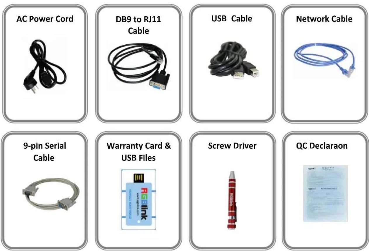
Note:
AC Power Cable supplied as standard according to desnaon market. USB is contained on the Warranty/Registraon Card. Please keep.
1.2 Product Overview
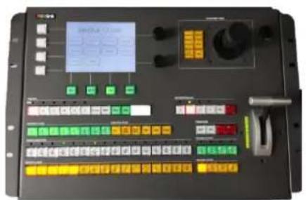
CP 2048 control mixer is the latest full funcon mixer enabling the user remote control of the input selecon, transion eects, and picture control of the RGBlink seamless switcher series. This allows the CP 2048 to be placed in control booth with operator who can manage all video control and mixing funcons, and safety keeping the video switcher and scaler with other control systems in the equipment rack.
The CP 2048 and seamless switcher can be simultaneously connected and controlled via TCP/IP, RS232 and USB connecons for exibility in system integraon. This allows for comprehensive picture controls, mul layers, and more than 24 digital eects utilizing the integrated T-bar and rotary knobs along with the 3D moon joysck.
Features
Input selecon control for Program and Preview outputs
Comprehensive picture controls
Transion eects, selecon buons, rotary buon and T-bar
Ethernet control and monitoring
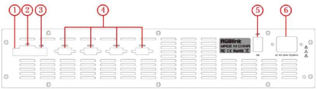
1.2.1 Back Panel
text_image
1 2 3 4 5 6 RGB/Link MODE IN CHINA RC CE RoHS GB AC 88-20Hz 50/HDHzControl Connectors
| 1 | DIP SwitchSwitch downward to be “ON” state, it works normally. Switch upward to be “OFF” state, it is updang. |
| 2 | RJ45 – EthernetConnect to an isolated network. Used for communicaons with devices. |
| 3 | USB-B – USBConnect to an isolated communicaon. Used for communicaons with devices. |
| 4 | DB9 – RS232Used for communicaons with devices. |
Power Connecon
| 5 | Power SwitchIlluminated power switch. |
| 6 | IEC – Power InputMain power input AC 85-264V Max 65W. |
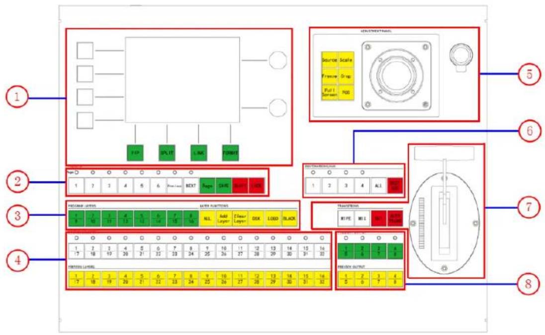
1.2.2 Top Panel
text_image
Diagram of an industrial control panel with labeled components and functional blocks, including input/output ports, display, and control panels.| Panel Instrucon | |||
| 1 | Touch Screen Menu Secon | 5 | Joysck Secon |
| 2 | Presets Secon | 6 | Desnaons/AUX |
| 3 | Layer Funcons Secon | 7 | Transion Secon |
| 4 | Source Selecon | 8 | Output Control Secon |
Touch Screen Menu Secon
| 1 | Touch ScreenFour ways to access a funcon or a menu:--Push a buon on the Touch Screen.--Push theSokeyadjacent to label.--UseNAVto move the highlight, then useADJ.--Touch a line to move the highlight, then useADJ. |
| SokeysSokey labels (when present) appear on the Touch Screen. | |
| NAVMove the highlight up and down, or adjust the labeled parameter. | |
| ADJAdjust the highlighted parameter. | |
| PIPPreview mode. | |
| SPLITStandard mode. | |
| LINKLink mode. | |
| FORMATOutput format selecon buon. |
Presets Secon
| 2 | 1/2/3/4/5/6Preset to recall a controller setup “a “Preset”) to Preview. Each button represents a single “look”. |
| PreviousJump to the previous valid preset. | |
| NEXTJump to the next valid preset. | |
| PagePush the buon, buon 1~6 LED light will be on, and select the page. | |
| SAVEPush the buon, buon 1~6 LED light will be on, and save the preset. | |
| SHIFTCP 2048 V1.0 can not support this funcon. | |
| LOCKLock front panel buon. |
Layer Funcons Secon
| 3 | Program LayersLayer 1 to layer 16. |
| ALLSelect all layers. | |
| Add LayerAdd the layer. | |
| Clear LayerClear the layer. | |
| DSKDSK setup. | |
| LOGOLOGO setup. | |
| BLACKBlack out. |
Source Selecon
| 4 | Source SeleconEach buon is an input that can be assigned to a PIP or Aux desnaon. |
| Green LEDsSolid: Source is on Program, associated desnaon is enabled.Blinking: Split is O. Layer is on Program, opposite layer on Preview. | |
| Preview LayersSolid: Source is on Preview, layer is not acve for modicaon.Blinking: Source is on Preview, blinking layer is acve for modicaon. |
Joysck Secon
| 5 | SourceAdjust source within PIP or layer. |
| ScaleAdjust the size of layers within PIP. | |
| FreezeFreeze the acve layer on Program. | |
| CropCrop boundaries of layer. | |
| SourceTake acve layer to full screen. | |
| Full ScreenAdjust the edges and posion of layers with PIP. | |
| JoysckAdjust the selected PIP. X-Axis (le/right). Y-Axis (up/down). Z-Axis (size). Z-Axis also adjusts value of highlighted parameter on Touch Screen. | |
| InterfaceConnect to low voltage “Scrip” light. |
Desnaons/AUX
| 6 | 1/2/3/4Push 1~4 to program IP to corresponding controlled device. |
| ALLPush to select all desnaons. Double-punch to turn all o. | |
| DEST/AUXPush to select two or more desnaons simultaneously. |
Transion Secon
| 7 | WIPESelect WIPE as the current transion type. |
| MIXSelect MIX as the current transion type. | |
| CUTInstantly cut images from Preview to Program. | |
| WIPE and MIX eects can be assigned on a per desnaon basis, and performed simultaneously. | |
| AUTO TRANSTransion automacally from Preview to Program. Use Eects Menu to set transion parameters. | |
| T-BarManually transion sources to/from Program, based on current transion type. |
Output Control Secon
| 8 | Program/Preview OutputSelect any combinaon of layers on Preview.Blinking: Layer is selected and acve for adjustment.Solid: Layer is selected on Preview, but is not acve for adjustment. |
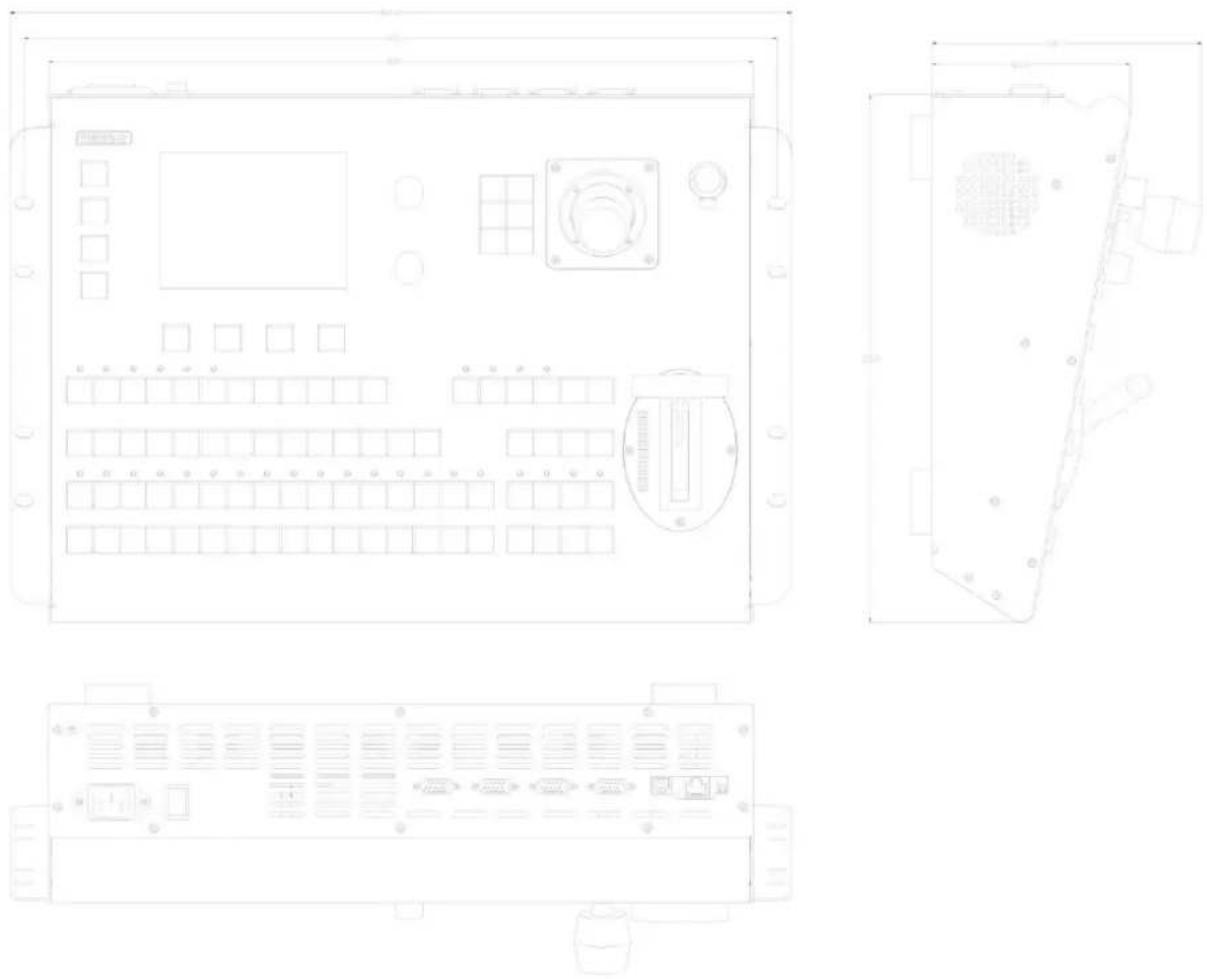
1.2.3 Dimension
Following is the dimension of CP 2048 for your reference:
2.1 CP 2048 Control VENUS X3
2.1.1 Connecon
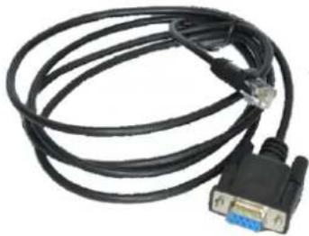
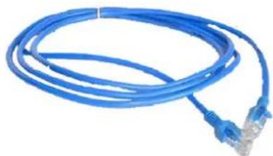
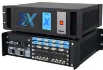
Connect CP 2048 and VENUS X3 by series cable (RS232) or Ethernet cable (RJ45).
text_image
Control panel interface with digital display and labeled buttons, showing various function keys and color-coded indicatorsCP 2048
natural_image
Coiled black cable with a white VGA port and blue connector (no text or symbols visible)Series Cable (RS232)
natural_image
Blue network cable with two connectors, no text or symbols visibleEthernet Cable (RJ45)
natural_image
Front view of a black server rack with multiple ports and a digital display (no visible text or symbols)VENUS X3
(1) Connect CP 2048 and VENUS X3 by Ethernet cable.
Step 1: Open VENUS X3 network funcon and check IP address, the steps are as follow:
Menu→System→Ethernet Setup→Network→On
Menu→System→Ethernet Setup→IP Address→192.168.0.100
Step 2: Connect CP 2048 and VENUS X3 by Ethernet cable (LAN port).
Step 3: Set CP 2048 IP address.
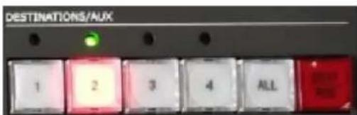
① Touch any number buon (1-4) shown as below "Device No.1-4" or select by "REMOTE" in the touch panel menu:
text_image
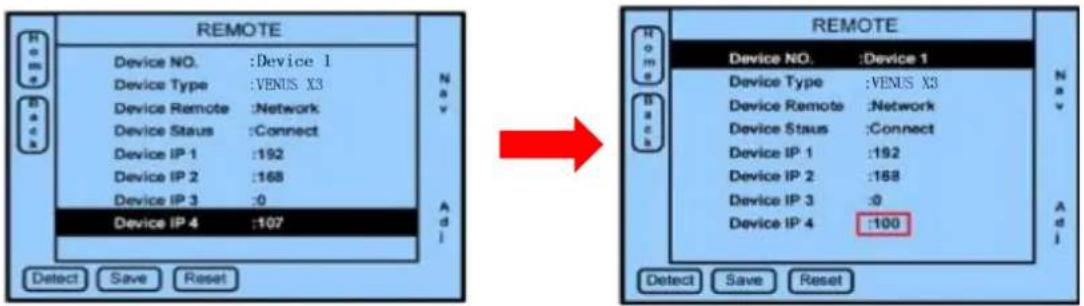
DESTINATIONS/AUX 1 2 3 4 ALL② Set up the same IP address of CP 2048 with VENUS X3: Device IP: 192.168.0.100.
text_image
REMOTE Device NO. :Device 1 Device Type :VENUS X3 Device Remote :Network Device Staus :Connect Device IP 1 :192 Device IP 2 :168 Device IP 3 :0 Device IP 4 :107 Add Detect Save Reset REMOTE Device NO. :Device 1 Device Type :VENUS X3 Device Remote :Network Device Staus :Connect Device IP 1 :192 Device IP 2 :168 Device IP 3 :0 Device IP 4 :100 Add Detect Save Reset(2) Use series port to connect CP 2048 and VENUS X3.
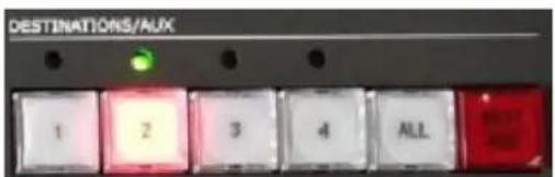
Step 1: Touch any number button (1-4) as below picture or by selecting "REMOTE" in touch menu to select the Device.
text_image
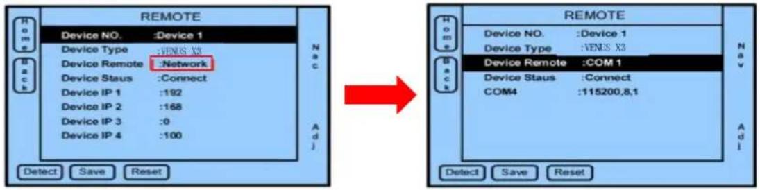
DESTINATIONS/ALIX 1 2 3 4 ALLStep 2: Change to VENUS X3 connec ng CP 2048 com port like COM1 in "NETWORK" under "Device Remote" menu, the step is as below gure 2.
text_image
REMOTE Device NO. :Device 1 Device Type :Venus X3 Device Remote :Network Device Staus :Connect Device IP 1 :192 Device IP 2 :168 Device IP 3 :0 Device IP 4 :100 Detect Save Reset ARMEN ARMEN Device NO. :Device 1 Device Type :Venus X3 Device Remote :COM 1 Device Staus :Connect COM4 :115200,8,1 ARMEN ARMEN ARMEN ARMEN ARMEN ARMEN ARMEN ARMEN ARMEN ARMEN ARMEN ARMEN ARMEN ARMEN(Figure 1)
(Figure 2)
Aer being setng up, touch the number buon (1-4) again, the CP 2048 will be automacally connected and sync.
Note: If CP 2048 display shows "Device Unconnected", please check if the previous setup, Ethernet cable or series port conneccon is correct or not.
2.1.2 Select Output Port
text_image
PROGRAM OUTPUT 1/5 2/6 3/7 4/8 Output: 1、2、3、4 PREVIEW OUTPUT 1/5 2/6 3/7 4/8 Output: 5、6、7、8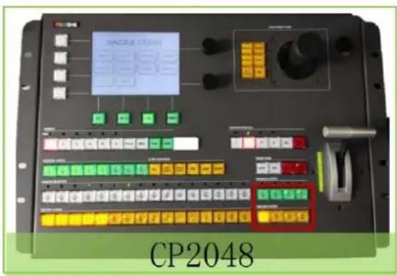
text_image
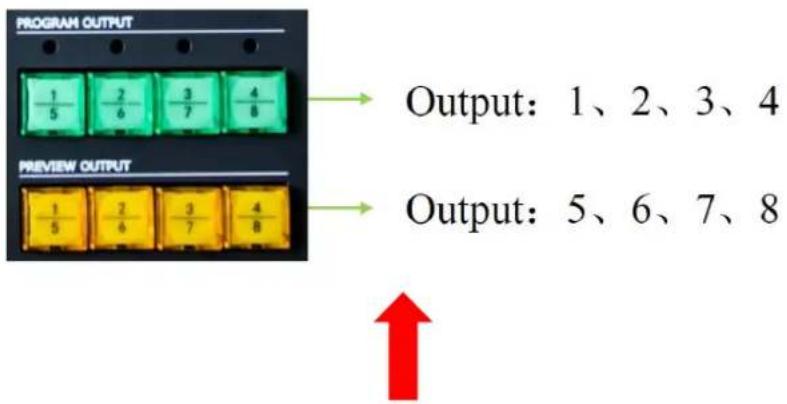
CP2048(1) The two lines buons are respectively referred to 8 output (two output cards) in VENUS X3.
(2) Select the corresponding number buon in CP 2048 for the output.
Note: The output will be changed to the followings under Preview Mode.
First Row: Output1, 3, 5, 7 (Program)
Second Row: Output2, 4, 6, 8 (Preview)
2.1.3 Size&Posion
text_image
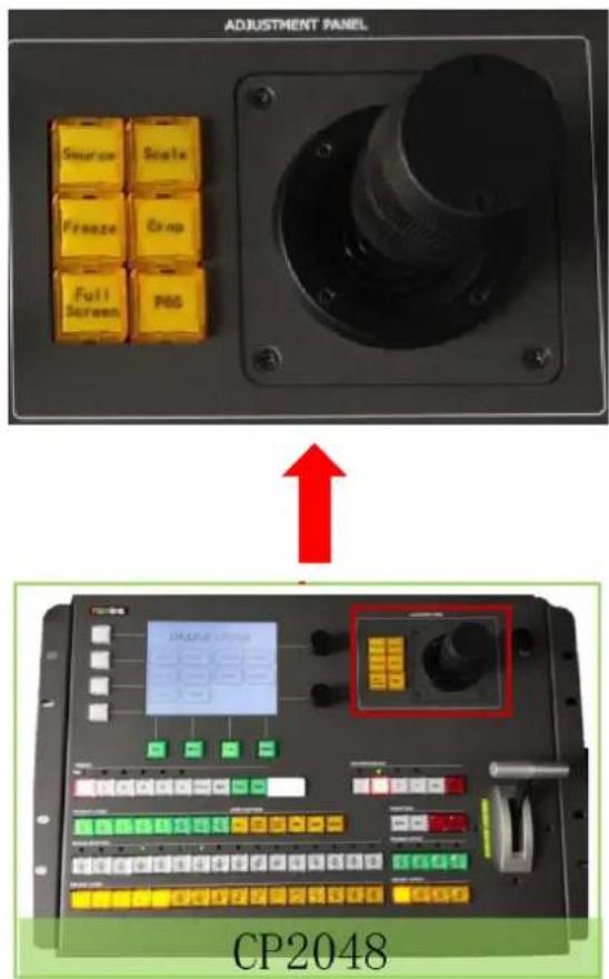
ADJUSTMENT PANEL Source Scale Freeze Crop Full Screen POS CP2048Change size or posion by the joysck and rotaon.
(1) Push "Scale" buon then change size by Joysck. When the joysck is turned to right or le,
the size will be zoomed or scaled horizontally. When the joysck is turn to up and down, the size will be zoomed or scaled vercally.
(2) Push the POS buon, then change the posion by joysck. When the joysck is turn to right or le, the X posion will be changed. When the joysck is turn to up and down, the Y posion will be changed.
(3) Push the CROP buon, the joystick can change the crop size and posion, when the joysck is turn to right or le, the size will be zoomed or scaled horizontally. When the joysck is turn to up and down, the size will be zoomed or scaled vercally.
(4) FREEZE: Select the current image to touch or release the Freeze buon.
(5) FULL SCREEN: Select the current image to set full screen.
2.1.4 Add Layer
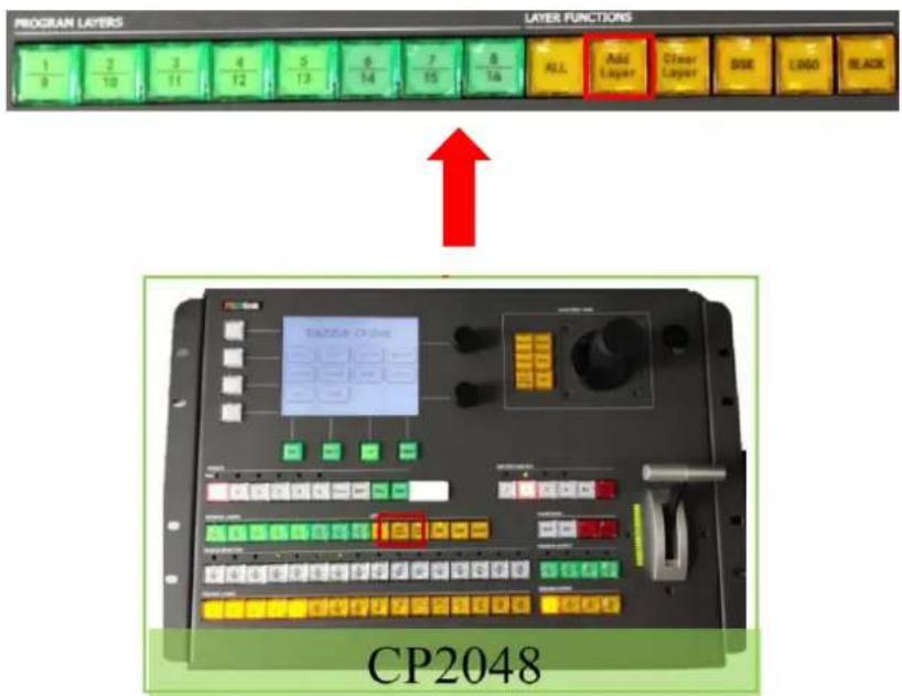
(1) Click [Add Layer] buon to add layer (Click Clear Layer button to clear layer).
text_image
PROGRAM LAYERS 1 2 3 4 5 6 7 8 9 10 11 12 13 14 15 16 LAYER FUNCTIONS ALL Add Layer Other Layer DISI LOGO BLACK CP2048(2) 16 buons are correspondingly for the 16 layers of VENUS X3, click the number buons to open the layers.
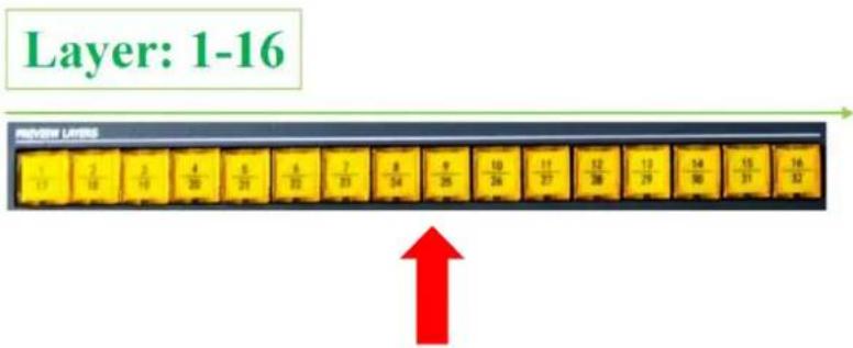
text_image
Layer: 1-16 REVIEW LINES 1/17 2/18 3/19 4/20 5/21 6/22 7/23 8/24 9/25 10/26 11/27 12/28 13/29 14/30 15/31 16/32 ↑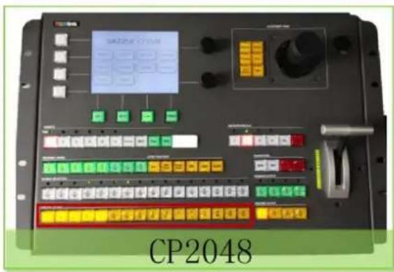
text_image
CP2048(3) 16 number buons correspondingly refer to 16 inputs of VENUS X3, click number buon to select the input.
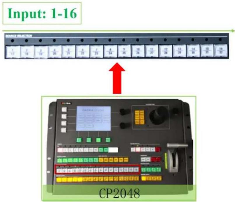
text_image
Input: 1-16 SOURCE SELECTION CP20482.1.5 Save&Load
text_image
PRESSETS Page 1 2 3 4 5 6 Previous NEXT Page SAVE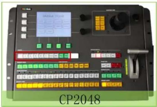
text_image
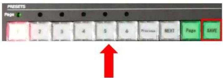
CP2048(1) Touch [SAVE] buon, the bank will be saved (6 Page×6 Bank).
(2) Load: Click the number buon to load the bank.
2.1.6 Logo Capture & Load
Select the layer and signal, push the [LOGO] button as below picture, the button will be ashing.
(1) View the display and select "Freeze" to freeze the LOGO image.
(2) Select "LOGO Capture" and select the number (1-10) to save the LOGO.
(3) Click rotaon to view if LOGO Capture is ok or not.
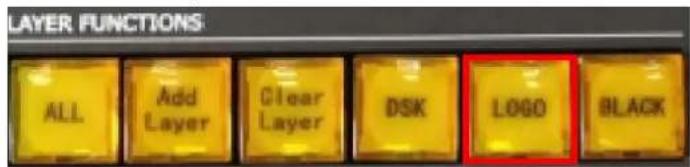
text_image
LAYER FUNCTIONS ALL Add Layer Clear Layer DSK LOGO BLACK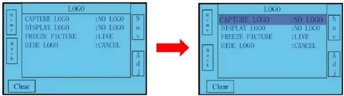
text_image
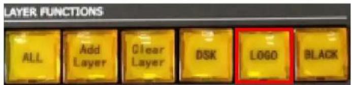
LOGO CAPTURE LOGO :NO LOGO DISPLAY LOGO :NO LOGO FREEZE PICTURE :LIVE HIDE LOGO :CANCEL N a v A d j Clear LOGO CAPTURE LOGO :NO LOGO DISPLAY LOGO :NO LOGO FREEZE PICTURE :LIVE HIDE LOGO :CANCEL N a v A d j ClearSelect the layer and signal, push the [LOGO] buon shown as below picture and the buon is ashing. View the monitor, select LOGO Display buon to select the saved logo (1-10), click rotaon to load the LOGO.
text_image
LAYER FUNCTIONS ALL Add Layer Clear Layer DSK LOGO BLACK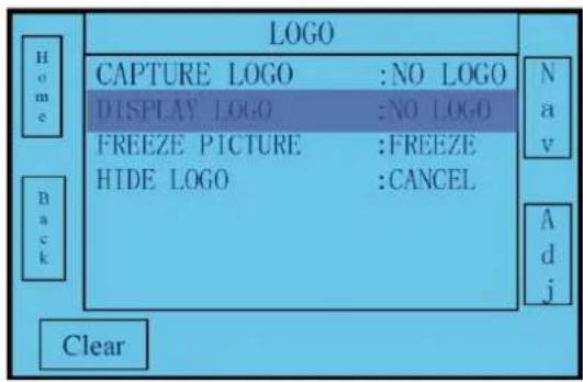
text_image
LOGO CAPTURE LOGO :NO LOGO DISPLAY LOGO :NO LOGO FREEZE PICTURE :FREEZE HIDE LOGO :CANCEL Home Back Clear Nav Adj2.1.7 EDID Management
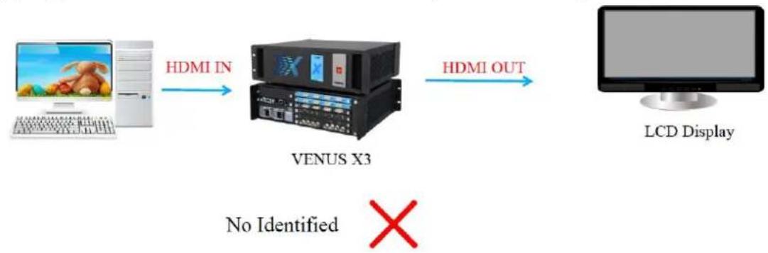
EDID Feature:
(1) Copy the rear-end device to the VENUS X3 HDMI input to realize recognition.
flowchart
graph LR
    A["Computer"] -->|HDMI IN| B["VENUS X3"]
    B -->|HDMI OUT| C["LCD Display"]
    D["No Identified"] -->|X| B
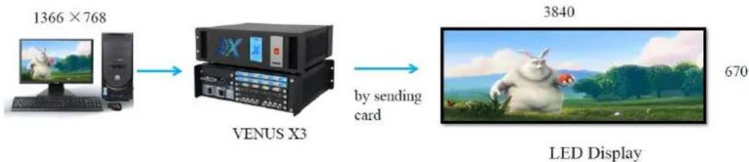
(2) Customized EDID can set higher resolution to realize pixel by pixel input.
flowchart
graph LR
    A["1366 × 768"] --> B["VENUS X3"]
    B --> C["LED Display"]
    style A fill:#f9f,stroke:#333
    style B fill:#ccf,stroke:#333
    style C fill:#cfc,stroke:#333
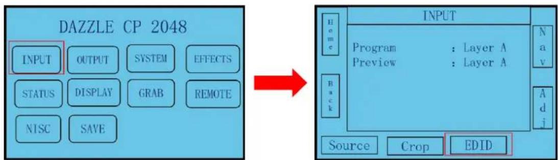
VENUS X3 can solve the two issue by EDID Management as below steps:
(1) Click [INPUT], and nd the [EDID] in boom right and click to enter EDID.
flowchart
graph LR
    A["INPUT"] --> B["OUTPUT"]
    B --> C["SYSTEM"]
    C --> D["EFFECTS"]
    E["STATUS"] --> F["DISPLAY"]
    F --> G["GRAB"]
    G --> H["REMOTE"]
    I["NTSC"] --> J["SAVE"]

    K["INPUT"] --> L["Program : Layer A"]
    L --> M["Preview : Layer A"]
    M --> N["Back"]
    N --> O["Source"]
    N --> P["Crop"]
    N --> Q["EDID"]
(2) For compatible issue, select to be changed signal format of source le and terminal port, click "Write" to change EDID
(3) For pixel by pixel output, click "Custom" in the bottom right, enter to customized resolution
page and click "Write" to change EDID.
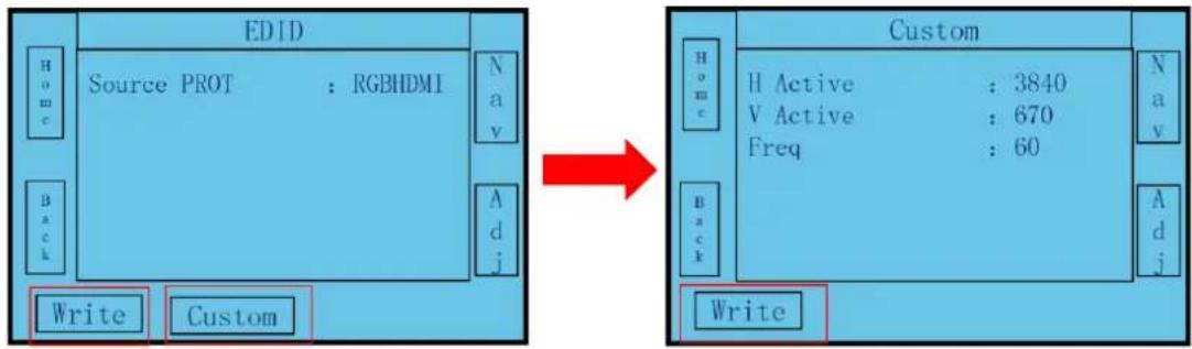
flowchart
graph LR
    subgraph EDID
        A["Source PROT : RGBHDMI"] --> B["Write"]
        C["Custom"] --> D["Write"]
    end

    subgraph Custom
        E["H Active : 3840"] --> F["Code: V Active : 670"]
        G["Freq : 60"] --> H["Code: N a v"]
        I["Write"] --> J["Code: A d j"]
    end
2.1.8 System Mode
Preview Mode, Standard Mode and Link Mode are supported when control VENUS X3.
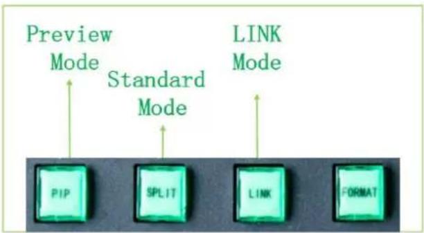
text_image
Preview Mode Standard Mode LINK Mode PIP SPLIT LINK FORMATPreview Mode
Click [PIP], make operaon as below noces:
(1) Shown as Figure 1 and click [YES].
(2) Shown as Figure 2, aer seng up the screen parameter, click [Please to set advance and save].
(3) Shown as Figure 3, aer seng up the screen parameter, click [Save to page 1_Bank 1] to enter to preview mode.
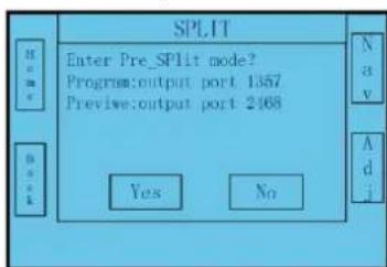
text_image
SPLIT Enter Pre_Split mode? Program:output port 1357 Preview:output port 2468 Yes No N a v A d i(Figure 1)
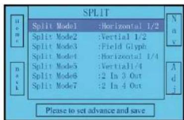
text_image
SPLIT Split Model :Horizontal 1/2 Split Mode2 :Vertical 1/2 Split Mode3 :Field Glyph Split Mode4 :Horizontal 1/4 Split Mode5 :Vertical1/4 Split Mode6 :2 In 3 Out Split Mode7 :2 In 4 Out Please to set advance and save(Figure 2)

text_image
HORIZONTAL 1/2 Total Width : 3840 Total Height : 1080 First Width : 1920 Save to page 1_Bank 1(Figure 3)
For preview mode, the bank-edit step is as below:
(1) Select output in [PREVIEW OUTPUT].
(2) Select layer in [SOURCE SELECTION].
(3) Select input source in [PREVIEW LAYERS].
(4) Edit the bank by the rotaon buon.
(5) Switch Bank to Program output by T-bar or [AUTO TRANS]. (Each output can be 4 layers at
maximum).

flowchart
graph LR
    A["Preview"] -->|By_T-bar_or["AUTO TRANS"]| B["PROGRAM"]
Standard Mode
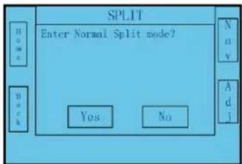
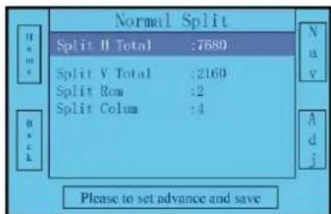
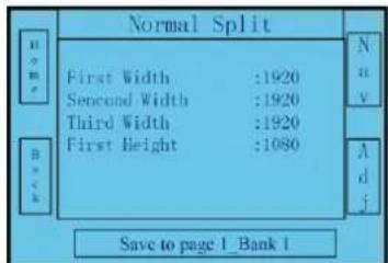
Click [SPLIT], make operaon as below noces:
(1) Shown as Figure 1, click [YES].
(2) Shown as Figure 2, select split mode and click [Please to set advance and save].
(3) Shown as Figure 3, set up the screen parameter and click [Save to page 1_Bank 1] to enter to standard mode.
text_image
SPLIT Enter Normal Split mode? Yes No N o v A d j(Figure 1)
text_image
Normal Split Split H Total :7680 Split V Total :2160 Split Row :2 Split Column :4 Please to set advance and save(Figure 2)
text_image
Normal Split First Width :1920 Second Width :1920 Third Width :1920 First Height :1080 Save to page 1_Bank 1(Figure 3)
For standard mode, the bank-edit step is below:
(1) Select output in [PREVIEW OUTPUT].
(2) Select layer in [SOURCE SELECTION].
(3) Select input source in [PREVIEW LAYERS].
(4) Edit the bank by rotaon.

natural_image
Collage of colorful balloons, beach photo, landscape photo, and waterfall (no text or symbols)LED Screen
Link Mode
(1) Connect output 6 and 8 to any other input (1-16) by two DVI cables independently.
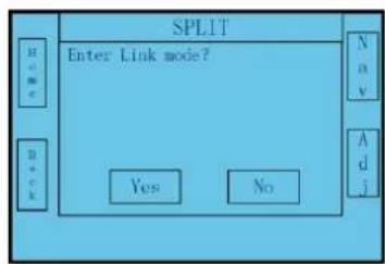
(2) Click [LINK] buon to make operaon according to the note in screen:
A. As shown in Figure (1), click [YES].
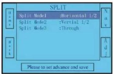
B. As shown in Figure (2), select split mode and click [Please to set advance and save].
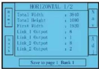
C. As shown in Figure (3), set screen parameter by rotaon buon and click [Save to page 1_Bank 1] to enter to the LINK Mode.
text_image
SPL1T Enter Link mode? Yes No N a v A d j(Figure 1)
text_image
SPLIT Split Mode1 :Horizontal 1/2 Split Mode2 :Vertical 1/2 Split Mode3 :Through Please to set advance and save(Figure 2)
text_image
HORIZONTAL 1/2 Total Width : 3840 Total Height : 1080 First Width : 1920 Link_1 Output : 6 Link_1 Output : 1 Link_2 Output : 8 Link_2 Output : 2 Save to page 1_Bank 1(Figure 3)
For Link Mode, the bank edit steps as below:
(1) Select output in [PREVIEW OUTPUT].
(2) Select layer in [SOURCE SELECTION].
(3) Select input source in [PREVIEW LAYERS].
(4) Edit the bank by rotaon buon.
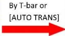
(5) Switch then bank to the LED screen by T-bar or [AUTO TRANS] (5 layers at maximum).

natural_image
Collage of colorful images including a child playing with a ball, an airplane on a beach, a water feature, and an X series logo (no text or symbols in the main visual elements)PREVIEW

natural_image
Collage of colorful images including a child playing with toys, a horse on a beach, an X series logo, and a waterfall (no text or symbols)PROGRAM
2.2 CP 2048 Control VSP 5360
2.2.1 Connecon
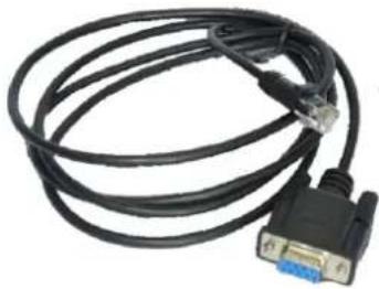
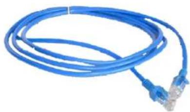
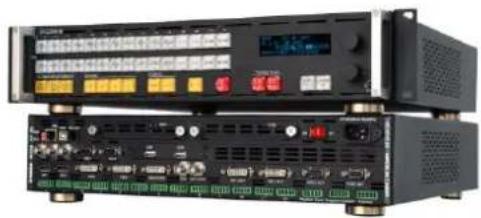
Connect CP 2048 and VSP 5360 by series cable (RS232) or Ethernet cable (RJ45).
text_image
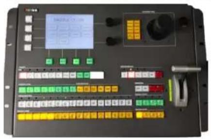
Control panel interface with digital display and multiple function buttons, including a numeric keypad and color-coded function blocksCP 2048
natural_image
Coiled black cable with a V2D port and blue connector (no text or symbols visible)Series Cable (RS232)
natural_image
Blue network cable with two Ethernet ports, no text or symbols visibleEthernet Cable (RJ45)
natural_image
Front view of a black electronic device with multiple ports and control panels (no visible text or labels)VENUS X3
(1) Connect CP 2048 and VSP 5360 by Ethernet cable.
Step 1: Open VSP 5360 network funcon and check IP address, the steps are as follow:
Menu→System→Ethernet Setup→Network→On
Menu→System→Ethernet Setup→IP Address→192.168.0.100
Step 2: Connect CP 2048 and VENUS X3 by Ethernet cable (LAN port).
Step 3: Set CP 2048 IP address.
① Touch any number button (1-4) shown as below "Device No.1-4" or select by "REMOTE" in the touch panel menu:
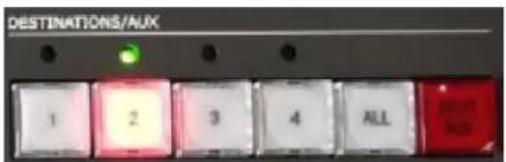
text_image
DESTINATIONS/AUX 1 2 3 4 ALL② Set up same IP address of CP 2048 with VENUS X3: Device IP: 192.168.0.100.
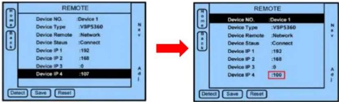
text_image
REMOTE Device NO. :Device 1 Device Type :VSP5360 Device Remote :Network Device Staus :Connect Device IP 1 :192 Device IP 2 :168 Device IP 3 :0 Device IP 4 :107 Add Detect Save Reset REMOTE Device NO. :Device 1 Device Type :VSP5360 Device Remote :Network Device Staus :Connect Device IP 1 :192 Device IP 2 :168 Device IP 3 :0 Device IP 4 :100 Add Detect Save Reset(2) Use series port to connect CP 2048 and VSP 5360.
Step 1: Touch any number button (1-4) as below picture or by selecting "REMOTE" in touch menu to select the Device.
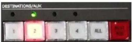
text_image
DESTINATIONS/AUX 1 2 3 4 ALLStep 2: Change to VSP 5360 connec ng CP 2048 com port like COM1 in "NETWORK" under "Device Remote" Menu, the step is as below gure 2.
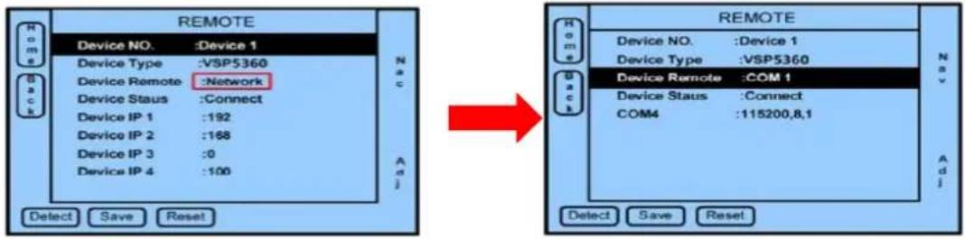
(Figure 1)
(Figure 2)
Aer being setng up, push the number buon (1-4) again, the CP 2048 will be automacally connected and sync.
Note: If CP 2048 display shows "Device Unconnected", please check if the previous setup, Ethernet cable or series port conneccon is correct or not.
2.2.2 Edit the Input Signal
Way 1:
Push the buons on [PREVIEW LAYERS] buon, or through the INPUT opons in the main menu (Figure 1), then enter to the SOURCE sengs (Figure 2) the 4 layers can be edited, user can select the signal source from buon 1\~16 in PREVIEW area. For example, set DVI1 to layer 1, VGA2 to layer 2, DVI1 to layer 3, CV2 to layer 4 (Figure 3).
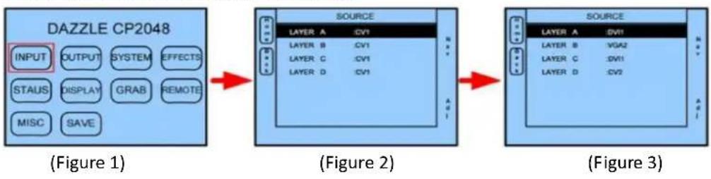
flowchart
graph LR
    A["DAZZLE CP2048"] --> B["(Figure 1)"]
    B --> C["(Figure 2)"]
    C --> D["(Figure 3)"]
Way 2:
Click the buons as follows, the buon lights, push the [Add Layer] or [Clear Layer] key to add or delete the layer.
(1) In Standard Mode, open layer A, layer B and layer C, which corresponding to buon 1, 2 and 3 in [PROGRAM LAYERS] area.
(2) In the three screen mode, open layer A, layer B, layer C and layer D, which corresponding to buon 1, 2, 3 and 4 in [PROGRAM LAYERS] area.

text_image
PROGRAM LAYERS LAYER FUNCTIONS 1/9 2/10 3/11 4/12 5/13 6/14 7/15 8/16 ALL Add Layer Clear Layer DSK LOGO BLACK2.2.3 Output Resoluon Seng
Push buon [FORMAT], or the OUTPUT opon in the main menu, and enter to the output format menus, turn the rotary knob to select the resoluon according to actual need.
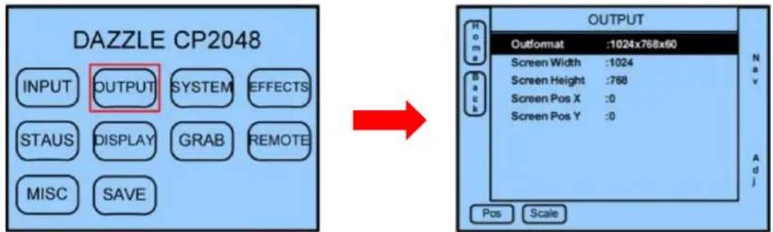
text_image
DAZZLE CP2048 INPUT OUTPUT SYSTEM EFFECTS STATUS DISPLAY GRAB REMOTE MISC SAVE OUTPUT Home Back OUTPUT Outformat :1024x768x60 Screen Width :1024 Screen Height :768 Screen Pos X :0 Screen Pos Y :0 Pos Scale Nav Adj(Figure 1)
(Figure 2)
2.2.4 Switch the Signal
(1) WIPE will acve the layers switch with plus transion dened.
(2) MIX will acve fade in fade out
(3) CUT will switch the layers from the top one to the boom one without delay.
(4) AUTO TRANS will take the preview to the program output via WIPE or MIX.
(5) User can also use T-BAR to do the transition via fade in fade out, and can overlay layers via stopping in a parcular posion. LED bar shows the fusion percentage.
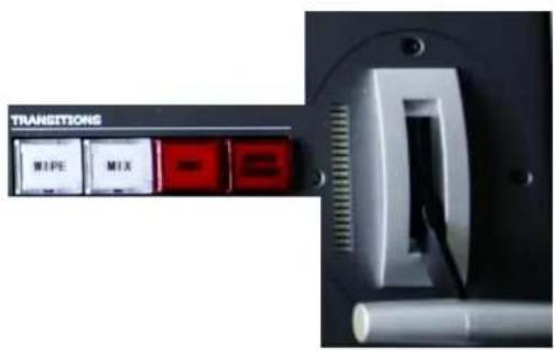
text_image
TRANSITIONS WIPE MIX2.2.5 Scale
Work with this part of buons and the joysck as the picture, user can set display windows size, posion and zoom in operaon easily via set up the parameters: Width, Height, X for start point of horizontal coordinate, Y for start point of vercal coordinate.
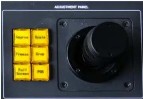
text_image
ADJUSTMENT PANEL Source Scale Freeze Crop Full Screen POS(1) Push "Scale" buon then change size by Joysck. When the joysck is turn to right or le, the size will be zoomed or scaled horizontally. When the joystick is turn to up and down, the size will be zoomed or scaled vercally.
(2) Push the POS buon, then change the posion by joysck. When the joysck is turn to right or le, the X posion will be changed. When the joysck is turn to up and down, the Y posion will be changed.
(3) Push the CROP buon, the joysck can change the crop size and position, when the joysck is turn to right or le, the size will be zoomed or scaled horizontally. When the joysck is turn to up and down, the size will be zoomed or scaled vertically.
(4) FREEZE: Select the current image to touch or release the Freeze button.
(5) FULL SCREEN: Select the current image to set full screen.
2.2.6 Logo Capture & Load
Select the layer and signal, push the [LOGO] button as below picture, the button will be ashing.
(1) Select the signal that to be the LOGO.
(2) View the display and select "Freeze" to freeze the LOGO image.
(3) Crop the LOGO image.
(4) Select "LOGO Capture" and select the LOGO 1 or LOGO 2 to save the LOGO.
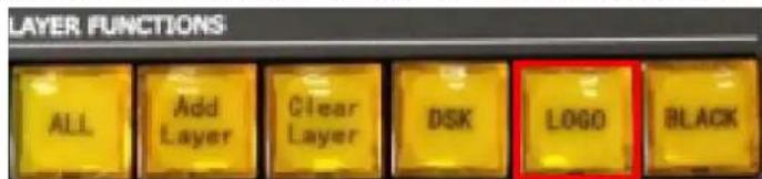
text_image
LAYER FUNCTIONS ALL Add Layer Clear Layer DSK(LOGO BLACK)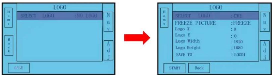
text_image
LOGO SELECT LOGO :NO LOGO Nav A j GRAD LOGO SELECT LOGO :CV1 FREEZE PICTURE :FREEZE Logo X :0 Logo Y :0 Logo Width :1920 Logo Height :1080 SAVE TO :LOC01 START BackSelect the layer and signal, push the [LOGO] buon shown as below picture and the buon is ashing. Turn the rotary knob, and display "LOGO1" or "LOGO2" on the monitor, click rotation to load the LOGO.

text_image
PROGRAM LAYERS LAYER FUNCTIONS 1/9 2/10 3/11 4/12 5/13 6/14 7/15 8/16 ALL Add Layer Clear Layer BSK LOGO BLACK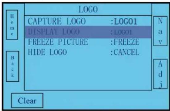
text_image
LOGO CAPTURE LOGO :LOG01 DISPLAY LOGO :LOG01 FREEZE PICTURE :FREEZE HIDE LOGO :CANCEL Home Back Clear Nav AdjNote:
(1) In Standard Mode, user can capture and load LOGO in Layer A, B, C and D. User can crop the LOGO. When load the LOGO, it will full screen automacally.
(2) In 3 Screen Preview Mode, the LOGO can be captured only in Layer C. User can scale and crop the LOGO. When load the LOGO, it will display in the adjusted size.
In Standard Mode

natural_image
Woman in traditional attire standing on a wooden bridge surrounded by dense green foliage (no text or symbols visible)Before capture

natural_image
Woman in traditional attire sitting on a bench outdoors with greenery background (no visible text or symbols)Aer crop and capture
In 3 Screen Preview Mode

natural_image
Woman in traditional attire standing on a wooden bridge surrounded by dense green trees under a blue sky (no text or symbols visible)Before capture

natural_image
Night scene at dusk with illuminated city skyline and river, inset shows a person in green (no visible text or symbols)Aer crop and capture
2.2.7 Save&Load
(1) There are 6 pages memory, and each page has 6 conguraons, so in total there will be max 36 conguraons. Comment use each page for one external device, and it will be convenience to acve the control when there are more external video devices in connected. Push Page and
select the page number which will be used to save, and push SAVE buon to be ready to save the conguraons, and push buon 1 to 6, will save the current conguraons to the acve page memory separately.
(2) User can push Page buon and select the page number which will be used to load, and load the memory number under the page. Also can use Next to view the dened memory.

text_image
PRESETS Page 1 2 3 4 5 6 Previous NEXT Page SAVEStandard Mode
Edit the scene in preview mode before saving, as saving parameters is only for the scene on Program. Then output to the Program by the T-bar or [AUTO TRANS], click [SAVE], and save to the corresponding page and conguraons. As shown in the gure below:

text_image
By T-bar or [AUTO TRANS] X SERIES PROGRAMPush the buon that will load, the program and preview will display the loaded scene. As shown in the gure below:

natural_image
Two side-by-side images: one showing a child playing with a ball, the other showing a child in a beach with a bucket; both lack text or symbols.3 Screen Preview Mode
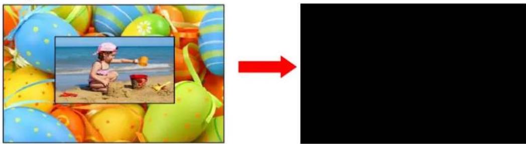
Edit the scene in preview mode before saving, as saving parameters is only for the scene on Program. Then click [SAVE], and save to the corresponding page and conguraons. As shown in the gure below:
natural_image
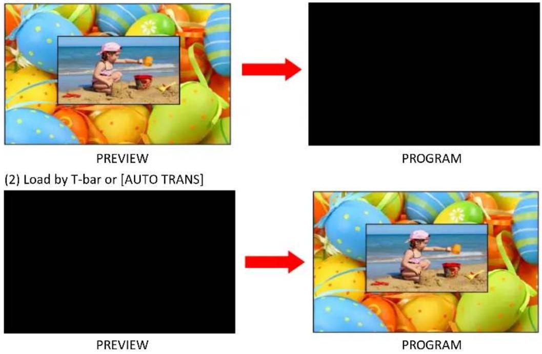
Illustration of a child playing on a beach with a red arrow pointing to the right (no text or symbols)Note: In 3 Screen Preview Mode, user do not need to output the scene to the Program. Push the buon that will load, the scene will display on the preview, check the parameter, then output to the Program by T-bar or [AUTO TRANS], as show in the gure below:
(1) Load
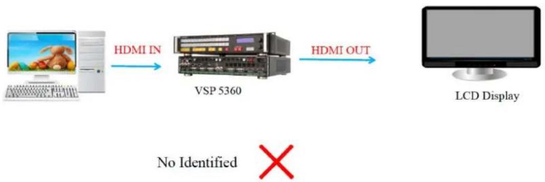
2.2.8 EDID Management
EDID Feature:
(1) Copy the rear-end device to the VSP 5360 HDMI input to realize recognition.
(2) Customized EDID can set higher resolution to realize pixel by pixel input.
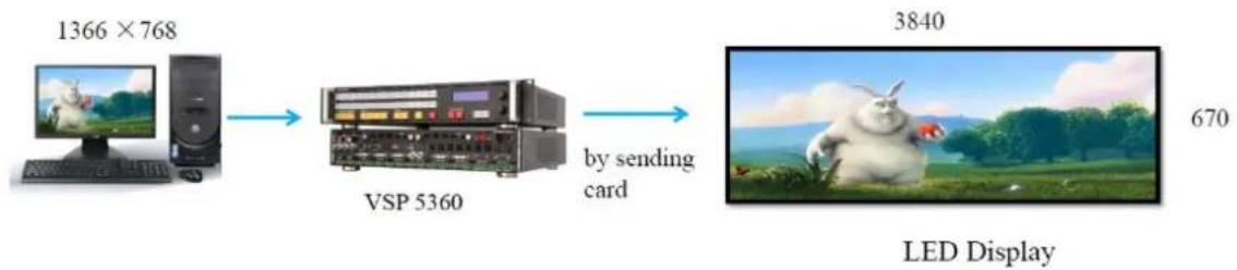
flowchart
graph LR
    A["Computer 1366 × 768"] --> B["VSP 5360"]
    B --> C["LED Display"]
    D["by sending card"] --> C
VSP 5360 can solve the two issue by EDID Management as below steps:
(1) Click [INPUT], and nd the [EDID] in boom right and click to enter EDID.
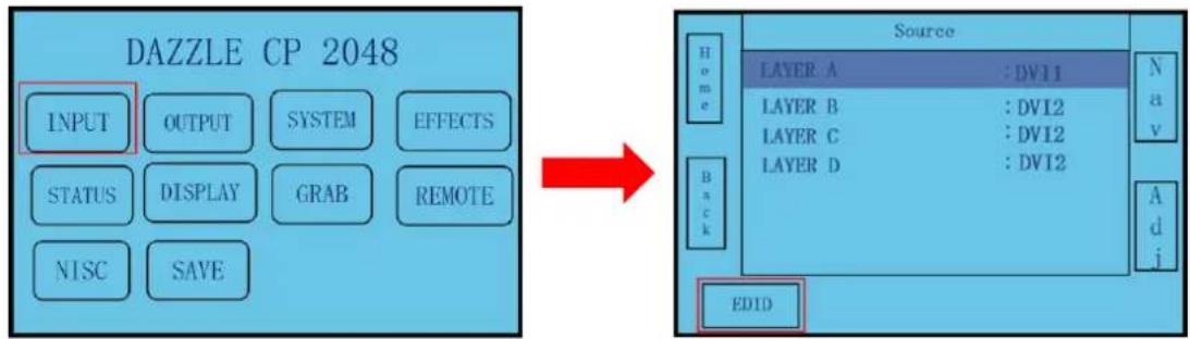
flowchart
graph LR
    A["INPUT"] --> B["OUTPUT"]
    B --> C["SYSTEM"]
    C --> D["EFFECTS"]
    E["STATUS"] --> F["DISPLAY"]
    F --> G["GRAB"]
    G --> H["REMOTE"]
    I["NISC"] --> J["SAVE"]

    K["EDID"] --> L["Source"]
    L --> M["Layer A : DV11"]
    L --> N["Layer B : DV12"]
    L --> O["Layer C : DV12"]
    L --> P["Layer D : DV12"]
    L --> Q["Back"]
    L --> R["Home"]
    L --> S["Nav"]
    L --> T["Adj"]
(2) For compatible issue, select to be changed signal format of source le and terminal port, click "Write" to change EDID.
(3) For pixel by pixel output, click "Custom" in the bottom right, enter to customized resolution page and click "Write" to change EDID.
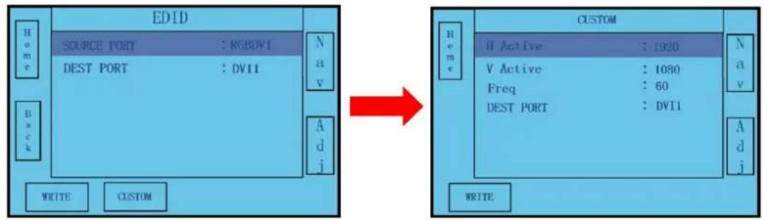
flowchart
graph LR
    subgraph EDID
        A["EDID"] --> B["SOURCE PORT : RGBDV1"]
        A --> C["DEST PORT : DV11"]
        D["WRITE"] --> E["CUSTOM"]
        F["Nav"] --> G["Adj"]
        H["Back"] --> I["Write"]
    end

    subgraph CUSTOM
        J["CUSTOM"] --> K["Hive: II Active : 1920"]
        J --> L["VActive: 1080"]
        J --> M["Freq: 60"]
        J --> N["DEST PORT: DV11"]
        O["Write"] --> P["Custom"]
        Q["Nav"] --> R["Adj"]
        S["Back"] --> T["Write"]
2.2.9 System Mode
3 Screen Preview Mode
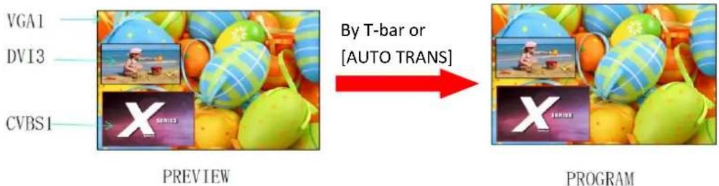
Select [SYSTEM] in the main menu of CP 2048, then select <3 Screen Preview Mode>. In 3 Screen Preview Mode, it can realize seamless switching between 3 channels. Select Layer 1, Layer 2 and Layer 3 in [PROGRAM LAYER] area, then select the signal in [PREVIEW LAYERS], and output it to the LED screen by T-bar or [AUTO TRANS]. Layer A and Layer D support DVI3/SDI/LOGO output, and layer B and layer C, any signal.
For example, to display the DVI3, VGA1, CVBS1 on preview monitor.
(1) Select Layer 3, and select [VGA1] in [PREVIEW LAYERS] area, the [VGA1] light is on.
(2) Select Layer 1, and select [DVI3] in [PREVIEW LAYERS] area, the [DVI3] light is on.
(3) Select Layer 2, and select [CVBS1] in [PREVIEW LAYERS] area, the [CVBS1] light is on.
Then the VGA1, DVI3 and CV1 signals are displayed on the preview monitor display.
text_image
VGA1 DVI3 CVBS1 PREVIEW By T-bar or [AUTO TRANS] PROGRAMNote: User can do the scale for any layer, the layer only changed on preview output, but not changed on program output.
(1) Change the Layer

natural_image
Child playing in a sandy beach surrounded by colorful striped play balls (no text or symbols visible)
text_image
PROGRAM(2) By T-bar

natural_image
Game preview featuring colorful egg-themed blocks and a small inset image of a character on a beach (no text or symbols)
natural_image
Colorful beach toys with a child playing in the ocean, surrounded by colorful balloons (no text or symbols on the toys themselves)Standard Mode
Select [SYSTEM] in the main menu of CP 2048, then select
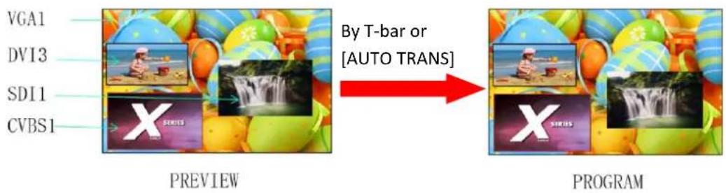
For example, to display the DVI3, VGA1, CVBS1 and SDI1 on preview monitor.
(1) Select Layer 3, and select [VGA1] in [PREVIEW LAYERS] area, the [VGA1] light is on.
(2) Select Layer 1, and select [DVI3] in [PREVIEW LAYERS] area, the [DVI3] light is on.
(3) Select Layer 2, and select [CVBS1] in [PREVIEW LAYERS] area, the [CVBS1] light is on.
(4) Select Layer 4, and select [SDI1] in [PREVIEW LAYERS] area, the [SDI1] light is on.
Then the VGA1, DVI3, CVBS1 and SDI1 signals are displayed on the preview monitor display.
flowchart
graph LR
    A["VGA1"] --> B["PREVIEW"]
    C["DVI3"] --> B
    D["SDI1"] --> B
    E["CVBS1"] --> B
    B --> F["PROGRAM"]
    style A fill:#f9f,stroke:#333
    style C fill:#f9f,stroke:#333
    style D fill:#f9f,stroke:#333
    style E fill:#f9f,stroke:#333
    style F fill:#ccf,stroke:#333
Note: User can do the scale for any layer, the layer only changed on preview output, but not changed on program output.

natural_image
Collage of colorful balloons and a waterfall image with no visible text or symbolsPREVIEW

natural_image
Collage of colorful balloons and a waterfall image, no visible text or symbolsPROGRAM
3.1 Product
200-2048-01-0 CP 2048
text_image
Offices Beijing Branch Office Shanghai Branch Office Xiamen Head Office Shenzhen Region Sales & Support Centre Web www.rgblink.comPhone
+86-592-577-1197
Sales
sales@rgblink.com
Support
support@rgblink.com
Social Media

@RGBLINK

/rgblink

+rgblink

/rgblink

rgblink
5.1 Terms & Denions
The following terms and denions are used throughout this guide.
- "ASCII": American Standard for Informaon Interchange. The standard code consists of 7-bit coded characters (8 bits including parity check) used to exchange informaon between data processing systems, data communicaon systems, and associated equipment. The ASCII set contains control characters and graphic characters.
- “Aspect rao”: The relationship of the horizontal dimension to the vercal dimension of an image. In viewing screens, standard TV is 4:3, or 1.33:1; HDTV is 16:9, or 1.78:1. Somemes the “:1” is implicit, making TV = 1.33 and HDTV = 1.78.
● "AV": Audio visual, or audio video. - A "Background" is an unscaled source, typically originang from a computer. A background source appears at the system's lowest priority — visually in back of all other sources.
- "Baudrate": Named of J.M.E. Baudot, the inventor of the Baudot telegraph code. The number of the electrical oscillaons per second, called baud rate. Related to, but not the same as, transfer rate in bits per second (bps).
- "Blackburst": The video waveform without the video elements. It includes the vercal sync, horizontal sync, and the chroma burst informaon. Blackburst is used to synchronize video equipment to align the video output. One signal is normally used to set up an enre video system or facility. Somemes it is called House sync.
- "BNC": Bayonet Neill-Concelman. A cable connector used extensively in television and named for its inventors. A cylindrical bayonet connector that operates with a twist-locking moon. To make the conncon, align the two curved grooves in the collar of the male connector with the two projecons on the outside of the female collar, push, and twist. This allows the connector to lock into place without tools.
- "Brightness": Usually refers to the amount or intensity of video light produced on a screen without regard to color. Somemes called "black level.
- "CAT 5": Category 5. Describes the network cabling standard that consists of four unshielded twisted pairs of copper wire terminated by RJ-45 connectors. CAT 5 cabling supports data rates up to 100 Mbps. CAT 5 is based on the EIA/TIA 568 Commercial Building Telecommunicaons Wiring Standard.
- "Color bars": A standard test paern of several basic colors (white, yellow, cyan, green, magenta, red, blue, and black) as a reference for system alignment and tesng. In NTSC video, the most commonly used color bars are the SMPTE standard color bars. In PAL video, the most commonly used color bars are eight full eld bars. In the computer, the most commonly used color bars are two rows of reversed color bars.
- "Color burst": In color TV systems, a burst of subcarrier frequency located on the back porch of the composite video signal. This serves as a color synchronizing signal to establish a frequency and phase reference for the chroma signal. Color burst is 3.58 MHz for NTSC
and 4.43 MHz for PAL.
- "Color temperature": The color quality, expressed in degrees Kelvin(K), of a light source. The higher the color temperature, the bluer the light. The lower the temperature, the redder the light. Benchmark color temperature for the A/V industry include 5000° K, 6500° K, and 9000° K.
- “Contrast rao”: The radio of the high light output level divided by the low light output level. In theory, the contrast radio of the television system should be at least 100:1, if not 300:1. In reality, there are several limitaons. In the CRT, light from adjacent elements contaminate the area of each element. Room ambient light will contaminate the light emied from the CRT. Well-controlled viewing conditions should yield a praccal contrast rao of 30:1 to 50:1.
- "DVI": Digital Visual Interface. The digital video connectivity standard that was developed by DDWG (Digital Display Work Group). This conneccon standard oers two dierent connectors: one with 24 pins that handles digital video signals only, and one with 29 pins that handles both digital and analog video.
- "EDID": Extended Display Idencaon Data – EDID is a data structure used to communicate video display informaon, including nave resoluon and vercal interval refresh rate requirements, to a source device. The source device will then output the opmal video format for the display based on the provided EDID data, ensuring proper video image quality. This communicaon takes place over the DDC – Display Data Channel.
- "Ethernet": A Local Area Network (LAN) standard socially known as IEEE 802.3. Ethernet and other LAN technologies are used for interconnecng computers, printers, workstaons, terminals, servers, etc. within the same building or campus. Ethernet operates over twisted pair and over coaxial cable at speeds starng at 10Mbps. For LAN interconnectivity, Ethernet is physical link and data link protocol reecng the two lowest layers of the OSI Reference Model.
- "Frame": In interlaced video, a frame is one complete picture. A video frame is made up of two elds, or two sets of interlaced lines. In a lm, a frame is one sll picture of a series that makes up a moon picture.
- "Gamma": The light output of a CRT is not linear with respect to the voltage input. The dience between what you should have and what is actually output is known as gamma.
- "HDMI" - High – Denion Mulmedia Interface: An interface used primarily in consumer electronics for the transmission of uncompressed high denion video, up to 8 channels of audio, and control signals, over a single cable. HDMI is the de facto standard for HDTV displays, Blu-ray Disc players, and other HDTV electronics. Introduced in 2003, the HDMI specicaon has gone through several revisions.
- "HDSDI": The high-denition version of SDI specied in SMPTE-292M. This signal standard transmits audio and video with 10 bit depth and 4:2:2 color quanzaon over a single coaxial cable with a data rate of 1.485 Gbit/second. Mulple video resoluons exists including progressive 1280x720 and interlaced 1920x1080 resoluon. Up to 32 audio signals are carried in the ancillary data.
- "JPEG" (Joint photographic Expects Group): Commonly used method of lossy compression for photographic images using a discreet cosine transfer funcon. The degree of compression can be adjusted, allowing a selectable tradeo between storage size and
image quality. JPEG typically achieves 10:1 compression with lile percepble loss in image quality. Produces blocking artifacts.
- “MPEG”: Moon Picture Expect Group. A standard commiee under the auspices of the Internaonal Standards Organizaon working on algorithm standards that allow digital compression, storage and transmission of moving image informaon such as moon video, CD-quality audio, and control data at CD-ROM bandwidth. The MPEG algorithm provides inter-frame compression of video images and can have an eecve compression rate of 100:1 to 200:1.
- "NTSC": The color video standard used in North America and some other parts of the world created by the Naonal Television Standards Commiee in the 1950s. A color signal must be compatible with black-and-white TV sets. NTSC ulizes an interlaced video signals, 525 lines of resoluon with a refresh rate of 60 elds per second (60 Hz). Each frame is comprised of two elds of 262.5 lines each, running at an eecve rate of 30 frames per second.
● "Operator": Refers to the person who uses the system.
- "PAL": Phase Alternate Line. A television standard in which the phase of the color carrier is alternated from line to line. It takes four full pictures (8 elds) for the color-to-horizontal phase relationship to return to the reference point. This alternaon helps cancel out phase errors. For this reason, the hue control is not needed on a PAL TV set. PAL, in many transmission forms, is widely used in Western Europe, Australia, Africa, the Middle East, and Micronesia. PAL uses 625-line, 50-led (25 fps) composite color transmission system.
- "PIP": Picture-in-Picture. A small picture within a larger picture created by scaling down one of the images to make it smaller. Each picture requires a separate video source such as a camera, VCR, or computer. Other forms of PIP displays include Picture-by-Picture (PBP) and Picture-with-Picture (PWP), which are commonly used with 16:9 aspect display devices. PBP and PWP image formats require a separate scaler for each video window.
- "Polarity": The positive and negative orientation of a signal. Polarity usually refers to the direcon or a level with respect to a reference (e.g. positive sync polarity means that sync occurs when the signal is going in the positive direcon).
- "RJ-45": Registered Jack-45. A connector similar to a telephone connector that holds up to eight wires, used for connecng Ethernet devices.
- "RS-232": An Electronic Industries Associaon (EIA) serial digital interface standard specifying the characteriscs of the communicaon path between two devices using either DB-9 or DB-25 connectors. This standard is used for relavely short-range communicaon and does not specify balanced control lines. RS-232 is a serial control standard with a set number of conductors, data rate, word length, and type of connector to be used. The standard species component conncon standards with regard to the computer interface. It is also called RS-232-C, which is the third version of the RS-232 standard, and is functionally identical to the CCITT V.24 standard.
- "Saturaon": Chroma, chroma gain. The intensity of the color, or the extent to which a given color in any image is free from white. The less white in a color, the truer the color or the greater its saturaon. On a display device, the color control adjusts the saturaon. Not to be confused with the brightness, saturaon is the amount of pigment in a color, and not the intensity. Low saturaon is like adding white to the color. For example, a low-saturated
red looks pink.
- "Scaling": A conversion of a video or computer graphic signal from a starng resoluon to a new resoluon. Scaling from one resoluon to another is typically done to optimize the signal for input to an image processor, transmission path or to improve its quality when presented on a parcular display.
- "SDI": Serial Digital Interface. The standard based on a 270 Mbps transfer rate. This is a 10-bit, scrambled, polarity independent interface with common scrambling for both component ITU-R 601 and composite digital video and four channels of (embedded) digital audio.
- "Seamless Switching": A feature found on many video switchers. This feature causes the switcher to wait until the vercal interval to switch. This avoid a glitch (temporary scrambling) which normally is seen when switching between sources.
- "SMPTE": Society of Moon Picture and Television Engineers. A global organizaon, based in the United States, that sets standards for baseband visual communicaons. This includes lm as well as video and television standards.
- "S-Video": A composite video signal separated into the luma ("Y" is for luma, or black and white information; brightness) and the chroma ("C" is an abbreviation for chroma, or color information).
- “Sync”: Synchronizaon. In video, sync is a means of controlling the timing of an event with respect to other events. This is accomplished with ming pulses to insure that each step in a process occurs at the correct me. For example, horizontal sync determines exactly when to begin each horizontal scan line. Vercal sync determines when the image is to be refreshed to start a new eld or frame. There are many other types of sync in video system.(Also known as “sync signal” or “sync pulse.”)
- "TCP/IP": Transmission Control Protocol/Internet Protocol. The communicaon protocol of the Internet. Computers and devices with direct access to the Internet are provided with a copy of the TCP/IP program to allow them to send and receive informaon in an understandable form.
- "USB": Universal Serial Bus. USB was developed by seven PC and telecom industry leaders (Compaq, DEC, IBM, Intel, Microso, NEC, and Northern Telecom). The goal was easy plug-and-play expansion outside the box, requiring no additional circuit cards. Up to 127 external computer devices may be added through a USB hub, which may be conveniently located in a keyboard or monitor. USB devices can be aached or detached without removing computer power. The number of devices being designed for USB connues to grow, from keyboards, mice, and printers to scanners, digital cameras, and ZIP drives.
- "VESA": Video Electronics Standards Associaon. A nonprot number organization dedicated to facilitang and promong personal computer graphics through improved standards for the benet of the end-user. www.vesa.org
- "VGA": Video Graphics Array. Introduced by IBM in 1987, VGA is an analog signal with TTL level separate horizontal and vercal sync. The video outputs to a 15-pin HD connector and has a horizontal scan frequency of 31.5kHz and vercal frequency of 70Hz (Mode 1, 2) and 60Hz (Mode 3). The signal is non-interlaced in modes 1, 2, and 3 and interlaced when using the 8514/A card ( 35.5kHz , 86Hz ) in mode 4. It has a pixel by line resolution of 640× 480 with a color palee of 16 bits and 256,000 colors.
- "YCrCb": Used to describe the color space for interlaced component video.
- "YPbPr": Used to describe the color space for progressive-scan (non-interlaced) component video.
5.2 Revision History
The table below lists the changes to the Video Processor User Manual.
| Format | Time | ECO# | Descripon | Principal |
| V1.0 | 2016-10-08 | 0000# | Release | Vira |