MSP 211 - Audio/video converter RGBlink - Free user manual and instructions
Find the device manual for free MSP 211 RGBlink in PDF.


| Product Type | Audio/Video Converter |
| Brand | RGBlink |
| Model | MSP 211 |
| DVI Input | 1x DVI-I socket; supports HDMI input via adapter (not hot-pluggable) |
| DVI Output | 1x DVI-I socket (shares with HDMI output; not hot-pluggable) |
| HDMI Output | 1x DVI-I socket (shared, compatible with HDMI 1.3) |
| Audio Output | 2x 1/4" balanced analog (48Kbps, 24-bit) |
| Supported Input Resolutions | 480i, 480p, 576i, 576p, 720p@50/60, 1080i@50/59.94/60, 1080p@50/59.94/60, 800x600@60, 1024x768@60/75, 1280x768@60, 1280x1024@60, 1440x900@60, 1400x1200@60, 1600x1200@60, 1680x1050@60 |
| Supported Output Resolutions | Same as input list (DVI output), plus 1080p@50/59.94/60 for HDMI |
| Communication | RS422 via RJ11 to DB9 cable for PC control |
| Power Supply | +12V DC, 1.5A (standard 3.5" interface power module) |
| Working Environment | 0°C to 45°C |
| Storage Environment | 10% to 90% humidity |
| Warranty | 1 year |
| Safety Features | Grounding through power cord; high voltage internal; do not remove covers; keep from damp, magnets, motors, TVs, transformers; avoid liquids and metal fragments |
| Control Software | AVMSP (Windows); supports Chinese/English, firmware upgrade, factory reset, serial settings |
| Firmware Upgrade | Via PC software (MCU and FPGA); requires admin password |
| Indicator LEDs | Red (power), Green (signal input) |
| Dimensions (Approx.) | Not specified |
| Weight (Approx.) | Not specified |
Frequently Asked Questions - MSP 211 RGBlink
User questions about MSP 211 RGBlink
0 question about this device. Answer the ones you know or ask your own.
Ask a new question about this device
Download the instructions for your Audio/video converter in PDF format for free! Find your manual MSP 211 - RGBlink and take your electronic device back in hand. On this page are published all the documents necessary for the use of your device. MSP 211 by RGBlink.
USER MANUAL MSP 211 RGBlink
Mini Video & Audio Converter User Manual
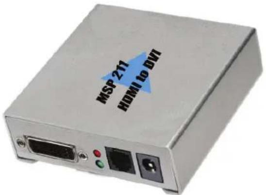
MSP 211 HDMI to DVI
RGBlink Science & Technology Co., Ltd.
The pictures and data in the user manual are consult only, if there is fluctuation, according to the real object please!
Headquarter: S603 Weiye Building Torch Hi-Tech Industrial Development Zone Xiamen, Fujian Province, P.R.C
Shenzhen office: Room A05, Floor 4, Building 24, Industry factory Nanshan Science & Technology Park, Shenzhen, Guangdong Province, P.R.C
Beijing office: No.27, west circle 3, Haidian District, Beijing, P.R.C
Tel: +86-592-5771197
Fax: +86-592-5771202
QQ:505941001
MSN: rgblink@hotmail.com
Skype: rgblink
Email: rgblinksales@gmail.com
File version
| Version | Date | ECO# | Description | principal | |
| 1.0 | 2010/10/19 | 0001 | Release | LISA | |
目录
1.0 Safety.... 1
2.2 Specification/Parameters 2
3.0 Description of button and interface.... 3
3.2 Interface description .... 4
4.0 Communication Software Control Guide 5
4.1 Running software .... 5
5.0 User Quick Start....9
1.0 Safety
 | The proper use of powerThe operating voltage for this product is 12V. This product is only workable under correct power condition, which is already mark on the back panel of the power. |
 | High VoltageThere are many high voltage components inside. |
 | Do not Remove Covers and PanelsDo not remove Covers in any conditions. There are not any spare components inside for maintenance, so do not maintain this product by userrselves, any requirement, please feel free to contact our service engineer. Keep heavy device from power cord. |
 | Grounding the Product and Use the Proper FuseThis product is grounded through the grounding conductor of the power cord. To Avoid electrical shock, plug the power cord into a properly wired receptacle before connecting to the product input or output terminals. |
 | Keep away from Magnet, Motor, TV and Transformer. |
 | Guard Against DampKeep using inside clean and dryness environment, once the device get wet, must remove power cord right now. |
 | Keep away ExploderDo not operate the device inside dangerous and easy explosive gas, which it may make fire, blast or something without expectation. |
 | Keep away Pour Liquid and FragmentIt is forbid to pour liquid, metal fragment or anything else inside this device to avoid fire and other accident. Once that happens, must remove power cord and try to make it clean before power on again. |
2.2 Specification/Parameters
| DVI Input | |
| Number of Inputs | 1 |
| Connector Standard DVI-I socket | |
| Input resolution(Supported Standards) | 480i;480p;576i;576p;720p@50;720p@60;1080i@50;1080i@60;1080p@50;1080p@60;800x600@60Hz1024x768@60Hz;1024x768@75Hz;1280x768@60Hz;1280x1024@60Hz;1440x900@60Hz;1400x1200@60Hz;1600x1200@60Hz;1680x1050x60Hz; |
| HDMI output (Share with DVI output) | |
| Number of Inputs | 1 |
| Connector Standard DVI-I socket | |
| Input resolution(Supported Standards) | 480i;480p;576i;576p;720p@50;720p@60;1080i@50;1080i@59.94;1080i@60;1080p@50; 1080p@59.94;1080p@60;800x600@60Hz;1024x768@60Hz;1024x768@75Hz;1280x768@60Hz;1280x1024@60Hz;1440x900@60Hz;1400x1050@60Hz;1600x1200@60Hz;1680x1050x60Hz; |
| DVI output (Share with HDMI output) | |
| Number of Inputs | 1 |
| Connector Standard DVI-I socket | |
| Input resolution(Supported Standards) | 480i;480p;576i;576p;720p@50;720p@60;1080i@50;1080i@59.94;1080i@60;1024x768@60Hz;1024x768@75Hz;1280x768@60Hz;1280x1024@60Hz;1440x900@60Hz;1400x1050@60Hz;1600x1200@60Hz;1680X1050x60Hz; |
| Audio output | |
| Number of outputs | 2 |
| Connetor Standard 1/4" socket | |
| Audio standard 48Kbps 24bit balance analogue audio | |
| Extras | |
| Communication | RS422 |
| Working Environment | 0°C~45°C |
| Power Supply +12V 3.5" interface power module | |
| Stored Environment 10% | to 90% |
| Product Warranty 1 years | |
3.0 Description of button and interface
3.1 Front panel interface description
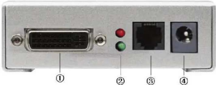
-
DVI input interface. Input the video & graphic signal from computer, DVD player, HDTV media player, DVI signal generator, HDMI signal generator and so on. (For HDMI input, use HDMI to DVI cable. Does not comments to support hot-plugging)
-
LED indicator:
Red Light: power indicator LED, it's on when device has power supply;
Green Light: Green means there is signal input;
-
COM, be used for host computer control. Please check User Quick Start for more detail;
-
Power, This device uses the standard 12V/1.5A power supply.
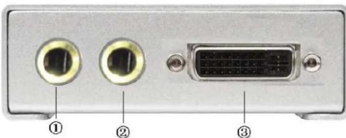
3.2 Back panel interface description
natural_image
Back panel of a computer interface showing two ports with connectors and a DVI port, labeled with numbers ①, ②, and ③ (no text or symbols on the components themselves)1-2. AUDIO output interface, used to access speaker or the audio amplifier system which compatible with 3.1 system. The audio of the HDMI signal will be separated from the video and output through this connector.
- DVI output interface, connect to the monitor or back end DVI device which has DVI interface. (This Connection does not comments to support hot-plugging) The video of the HDMI signal will be separated from the audio and output by this connector.
4.0 Communication Software Control Guide
AVMSP series of mini converter is equipped with user-friendly communication control software.
4.1 Running software
Double-click AVMSP software ; Software interface is as follows:
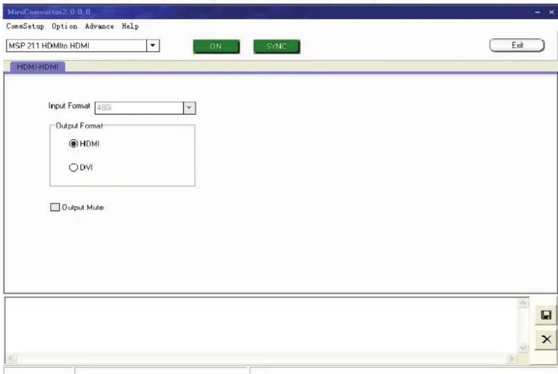
Fig. 4.1 MSP 211 Control Software
- Serial settings
User can set Comm Port and Comm Speed (Baudrate) through "Comm setup". User can select current using serial port by the pull-down arrow. Comm Speed should be 115200.
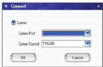
Fig. 4.2 MSP 211 Serial setting
- Language settings
This software supports both Chinese and English; User can switch the language by "language" menu.
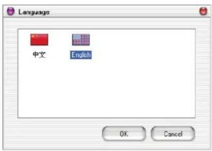
Fig. 4.3 MSP 211 Language settings
- Advance
In the advance menu, send CMD and device SN are only for engineers, Ordinary user do not need to set.
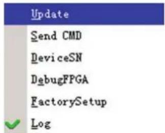
Fig. 4.4 MSP 211 Advance
MSP203 can upgrade MCU and FPGA firmware inside MSP 211, before upgrade user need to key in the password in the "Admin password" dialog.
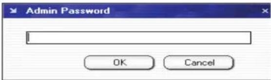
Fig. 4.5 MSP 211 "Admin password"
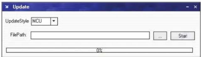
Fig. 4.6 MSP 211 "Update"
Click path button, Find out the updated bin file.
Click "Start" button to update
Click "Log" in the Advance menu, you can find out the log toolbar at the bottom of the software interface. Click "Log" again, the log toolbar will disappear from the software interface. Shown as below picture:
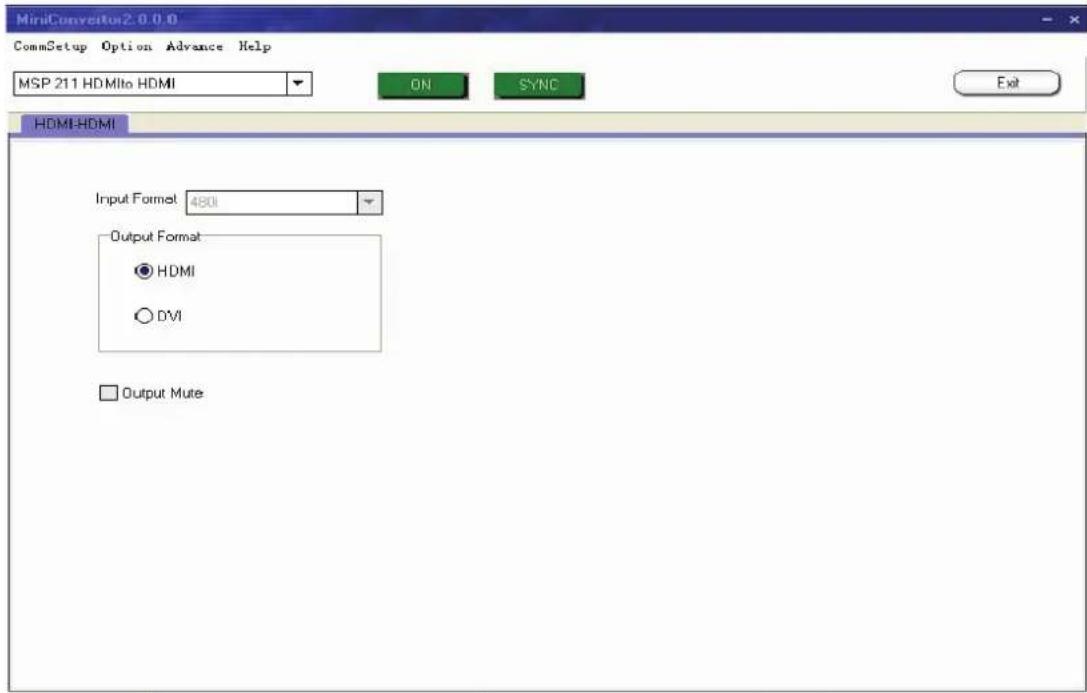
Fig. 4.7 MSP 211 Control Software

Save, User can save current log to specified path to review.

Remove, User can remove the log.
Factory Reset: User can set the status to the factory status.
- About
User can find out the software version and related information in "About" menu.
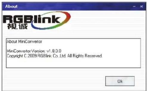
Fig. 4.8 MSP 211 "About"

- How to use
User need to choose current small converter Model in the pull-down firstly.
Shown as below:
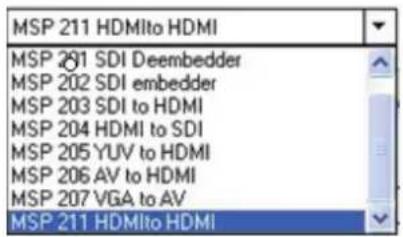
Fig. 4.9 MSP 211 "Choose Model"
ON
Click" on" button to open the serial, The button will become
OFF
when serialis opened. User can click the "Close" button if user want to close the serial.
SYNC
SYNC Click this button can download user config (settings) on software into MSP 211, but could not sync user config inside MSP 211 which by buttons.
Exit
Click this button can exit software.
- Input
The device will automatically read and display the format of DVI input, as follows:

Fig. 4.10 MSP 211 Optional Pictures
- Output
DVI output interface is compatible with HDMI 1.3; HDMI interface is able to embedded audio; If use DVI protocol, audio should go by additional CANNON to play. Select "Output Mute" to make device mute.
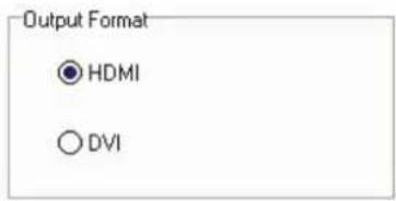
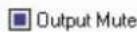
Fig. 4.11 MSP 211 Optional Pictures
5.0 User Quick Start
-
Connect DVI input from source and DVI output to back end device, audio to audio player;
-
Connect one end of the power adapter with the device, the other end into a socket. Plug in, red led light means the device get power, and green on means it got signal input works.
If user wants to change the mini converter output protocol, for example, from DVI to HDMI, should check following steps. Defaultly, the converter output as DVI.
- How does PC software control the device?
When using PC with COM, users can connect the device to PC through cable RJ11 to DB9.
1) Firstly connect the device by cable RJ11 to DB9, another end to PC or laptop if with RS232 connector;
2) Double click the software of AVMSP , seen as follows:
![小型变换器2.00.0 串口设置 选项 高级 帮助 MSP 211 HDMIto HDMI 开 同步 退出 HDMI-HDMI Input Format 480i Output Format ● HDMI ○ DVI ■ Output Mute Com1 Closed [MCU-????] [FPGA-????] [SN-????]](/content/2026/05/950481/images/7d2824dd91fbde515ebcb92e1366498d88ed1242e21e41cda9858130da5dbe33.jpg)
Fig. 5.2 MSP 211 Control Software
① Select current small converter Model as MSP 211 in the pull-down.
② User can set Comm Port and Comm Speed (Baudrate) through "Comm setup". User can select current using serial port by the pull-down arrow. Comm Speed should be 115200.
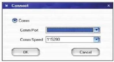
Fig. 5.3 MSP 211 Serial setting
Click" on" button to open the serial, The button will become

Click this button can realize host computer software data sync with MSP
211.
Remark: When user change output format, SYNC should be started to make device operate correctly, and this operation is saved to memory directly, user do not need to do save operation separately.
For other operations, please refer to the fourth part Communication Software Control Guide.
- Mini Video & Audio Converter User Manual
- RGBlink Science & Technology Co., Ltd.
- 目录
- Safety
- Specification/Parameters
- Description of button and interface
- Front panel interface description
- Back panel interface description
- Communication Software Control Guide
- Running software
- - Serial settings
- - Language settings
- - Advance
- - About
- - How to use
- ON
- OFF
- SYNC
- Exit
- - Input
- - Output
- User Quick Start
Brand : RGBlink
Model : MSP 211
Category : Audio/video converter