M2 - Controller RGBlink - Free user manual and instructions
Find the device manual for free M2 RGBlink in PDF.


| Product Type | Video Controller / Switcher |
| Brand | RGBlink |
| Model | M2 |
| Dimensions (W x D x H) | 320 x 200 x 45 mm |
| Weight | 1.5 kg |
| Power Supply | DC 12V, 2A |
| Power Consumption | 15 W |
| Input Video Interfaces | 2x HDMI, 1x VGA |
| Output Video Interfaces | 1x HDMI, 1x VGA |
| Supported Resolutions | Up to 1920x1080 @60Hz |
| Main Functions | Seamless switching, PIP, audio embedding, scaler |
| Control Interface | Front panel buttons, RS-232 |
| Chassis Material | Aluminum alloy |
| Operating Temperature | 0°C to 40°C |
| Storage Temperature | -20°C to 60°C |
| Cleaning | Use a soft dry cloth; avoid liquid cleaners |
| Safety | Class III device, use only with supplied power adapter |
| Spare Parts / Repairability | Contact authorized service center for parts |
| Warranty | 2 years from date of purchase |
Frequently Asked Questions - M2 RGBlink
User questions about M2 RGBlink
0 question about this device. Answer the ones you know or ask your own.
Ask a new question about this device
Download the instructions for your Controller in PDF format for free! Find your manual M2 - RGBlink and take your electronic device back in hand. On this page are published all the documents necessary for the use of your device. M2 by RGBlink.
USER MANUAL M2 RGBlink
natural_image
Line drawing of a portable electronic device with multiple control panels and buttons (no text or symbols)RGBlink
USER MANUAL
Article No: RGB-RD-UM-M2 E003
Revision No: V1.3
CONTENTS
CONTENTS....2
Declarations....4
FCC/Warranty....4
Operators Safety Summary....5
Installation Safety Summary.... 5
Chapter 1 Your Product....1
1.1 In the Box....1
1.2 Product Overview....2
1.2.1 Rear Panel....3
1.2.2 Front Panel....5
1.2.3 Dimension....10
Chapter 2 Installing Your Product.... 11
2.1 Plugging in Signals....11
2.2 Plugging in Main Power.... 11
2.3 Turning on Your Product....11
Chapter 3 Using Your Product....13
3.1 Using the MENU Button....13
3.2 Understanding the MENU Structure.... 14
3.3 Using the Menu....15
3.3.1 Understanding the Display.... 15
3.3.2 Understanding the Main Menu.... 16
3.3.3 Input Menu....16
3.3.4 Output Menu....17
3.3.5 Background Menu.... 18
3.3.6 Advance Menu....18
3.3.7 Language Menu.... 21
3.3.8 System Menu....21
3.3.9 Factory Reset Menu....22
3.4 PST Mode....23
3.4.1 Signal Selection....23
3.4.2 Add or Delete Layer 23
3.4.3 Freeze the Layer....23
3.4.4 Multiview Presets.... 25
3.4.5 Set the Position....25
3.4.6 Scale and Crop the Layer 26
3.4.7 DSK Settings....27
3.4.8 BLEND Settings....29
3.4.9 Mask Settings....30
3.4.10 Transition Settings.... 32
3.4.11 Adjust R,G,B of SDI,VGA,CVBS,USB Input....33
3.5 System Mode 35
3.5.1 Normal....35
3.5.2 4K1K....35
3.5.3 4K2K....41
3.5.4 Matrix....42
3.5.5 Presentation....43
3.6 Switching Layers....45
3.7 Background Picture....47
3.7.1 Input Source....47
3.7.2 Captured Picture....47
3.7.3 Picture file loaded with U Disk 48
3.8 Set the Output Resolution.... 52
3.8.1 Select the Output Resolution.... 52
3.8.2 Custom the Output Resolution....52
3.9 Using Black Out....54
3.10 Saving Views....55
3.11 Recall Saved Settings....56
Chapter 4 Ordering Codes....57
4.1 Product....57
4.2 Options....57
4.2.1 Input Options....57
4.2.2 Accessories....57
Chapter 5 Support....58
5.1 Contact Us....58
Chapter 6 Appendix....59
6.1 Specification....59
6.2 Upgrade....64
6.3 Custom OSD, MASK, LOGO, STILL by XTOQL 66
6.3.1 Installation of XTOOL.... 66
6.3.2 Custom OSD....72
6.3.3 Custom Effect....74
6.3.4 Custom Logo....75
6.3.5 Custom Still....76
6.4 Terms & Definitions....77
6.5 Revision History....81
Thank you for choosing our product!
This User Manual is designed to show you how to use this video processor quickly and make use of all the features. Please read all directions and instructions carefully before using this product.
Declarations
FCC/Warranty
Federal Communications Commission (FCC) Statement
This equipment has been tested and found to comply with the limits for a class A digital device, pursuant to Part 15 of the FCC rules. These limits are designed to provide reasonable protection against harmful interference when the equipment is operated in a commercial environment. This equipment generates, uses, and can radiate radio frequency energy and, if not installed and used in accordance with the instruction manual, may cause harmful interference to radio communications. Operation of this equipment in a residential area may cause harmful interference, in which case the user will be responsible for correcting any interference.
Guarantee and Compensation
RGBlink provides a guarantee relating to perfect manufacturing as part of the legally stipulated terms of guarantee. On receipt, the purchaser must immediately inspect all delivered goods for damage incurred during transport, as well as for material and manufacturing faults. RGBlink must be informed immediately in writing of any complaints.
The period of guarantee begins on the date of transfer of risks, in the case of special systems and software on the date of commissioning, at latest 30 days after the transfer of risks. In the event of justified notice of compliant, RGBlink can repair the fault or provide a replacement at its own discretion within an appropriate period. If this measure proves to be impossible or unsuccessful, the purchaser can demand a reduction in the purchase price or cancellation of the contract. All other claims, in particular those relating to compensation for direct or indirect damage, and also damage attributed to the operation of software as well as to other service provided by RGBlink, being a component of the system or independent service, will be deemed invalid provided the damage is not proven to be attributed to the absence of properties guaranteed in writing or due to the intent or gross negligence or part of RGBlink.
If the purchaser or a third party carries out modifications or repairs on goods delivered by RGBlink, or if the goods are handled incorrectly, in particular if the systems are commissioned operated incorrectly or if, after the transfer of risks, the goods are subject to influences not agreed upon in the contract, all guarantee claims of the purchaser will be rendered invalid. Not included in the guarantee coverage are system failures which are attributed to programs or special electronic circuitry provided by the purchaser, e.g. interfaces. Normal wear as well as normal maintenance are not subject to the guarantee provided by RGBlink either.
The environmental conditions as well as the servicing and maintenance regulations specified in this manual must be complied with by the customer.
Operators Safety Summary
The general safety information in this summary is for operating personnel.
Do Not Remove Covers or Panels
There are no user-serviceable parts within the unit. Removal of the top cover will expose dangerous voltages. To avoid personal injury, do not remove the top cover. Do not operate the unit without the cover installed.
Power Source
This product is intended to operate from a power source that will not apply more than 230 volts rms between the supply conductors or between both supply conductor and ground. A protective ground connection by way of grounding conductor in the power cord is essential for safe operation.
Grounding the Product
This product is grounded through the grounding conductor of the power cord. To avoid electrical shock, plug the power cord into a properly wired receptacle before connecting to the product input or output terminals. A protective-ground connection by way of the grounding conductor in the power cord is essential for safe operation.
Use the Proper Power Cord
Use only the power cord and connector specified for your product. Use only a power cord that is in good condition. Refer cord and connector changes to qualified service personnel.
Use the Proper Fuse
To avoid fire hazard, use only the fuse having identical type, voltage rating, and current rating characteristics. Refer fuse replacement to qualified service personnel.
Do Not Operate in Explosive Atmospheres
To avoid explosion, do not operate this product in an explosive atmosphere.
Installation Safety Summary
Safety Precautions
For all M2 processor installation procedures, please observe the following important safety and handling rules to avoid damage to yourself and the equipment.
To protect users from electric shock, ensure that the chassis connects to earth via the ground wire provided in the AC power Cord.
The AC Socket-outlet should be installed near the equipment and be easily accessible.
Unpacking and Inspection
Before opening M2 processor shipping box, inspect it for damage. If you find any damage, notify the
shipping carrier immediately for all claims adjustments. As you open the box, compare its contents against the packing slip. If you find any shortages, contact your sales representative.
Once you have removed all the components from their packaging and checked that all the listed components are present, visually inspect the system to ensure there was no damage during shipping. If there is damage, notify the shipping carrier immediately for all claims adjustments.
Site Preparation
The environment in which you install your M2 should be clean, properly lit, free from static, and have adequate power, ventilation, and space for all components.
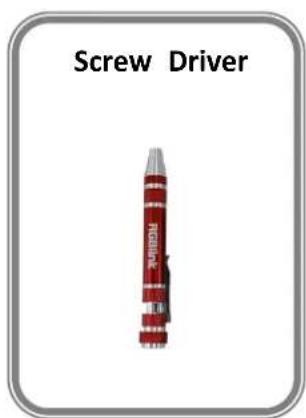
1.1 In the Box
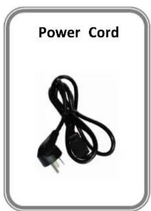
natural_image
Black power cord with a terminal plug, labeled 'Power Cord' above (no other text or symbols)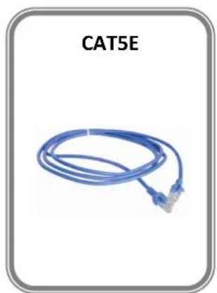
natural_image
Blue cable with connectors, labeled 'CAT5E' above (no other text or symbols)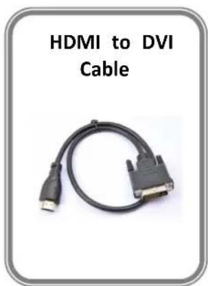
Note:
The USB file contains Warranty/Registration Card.
AC Power Cord supplied as standard according to the destination market.
1.2 Product Overview
All-in-one scaling and mixing just got even better.
Now you choose input options, now you configure output operations, now control transitions from the T-bar, now apply layer masks, now do more.
M2 redefines modern hands-on scaling and mixing for any environment.
Totally modular and flexible in configuration, M2 is packed with standard features to impress and present with ease.
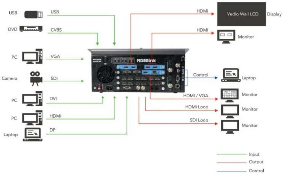
flowchart
graph TD
    A["USB"] -->|USB| B["RGBlink"]
    C["DVD"] -->|CVBS| B
    D["PC"] -->|VGA| B
    E["Camera"] -->|SDI| B
    F["PC"] -->|DVI| B
    G["PC"] -->|HDMI| B
    H["Laptop"] -->|DP| B
    B -->|HDMI| I["Vedio Wall LCD Display"]
    B -->|HDMI / VGA| J["Laptop"]
    B -->|HDMI Loop| K["Laptop"]
    B -->|SDI Loop| L["Laptop"]
    style B fill:#f9f,stroke:#333,stroke-width:2px
    linkStyle 0 stroke:#000,stroke-width:2px
    linkStyle 1 stroke:#000,stroke-width:2px
    linkStyle 2 stroke:#000,stroke-width:2px
    linkStyle 3 stroke:#000,stroke-width:2px
    linkStyle 4 stroke:#000,stroke-width:2px
    linkStyle 5 stroke:#000,stroke-width:2px
    linkStyle 6 stroke:#000,stroke-width:2px
    linkStyle 7 stroke:#000,stroke-width:2px
    linkStyle 8 stroke:#000,stroke-width:2px
    linkStyle 9 stroke:#000,stroke-width:2px
    linkStyle 10 stroke:#000,stroke-width:2px
    linkStyle 11 stroke:#000,stroke-width:2px
    linkStyle 12 stroke:#000,stroke-width:2px
    linkStyle 13 stroke:#000,stroke-width:2px
    linkStyle 14 stroke:#000,stroke-width:2px
    linkStyle 15 stroke:#000,stroke-width:2px
    linkStyle 16 stroke:#000,stroke-width:2px
    linkStyle 17 stroke:#000,stroke-width:2px
    linkStyle 18 stroke:#000,stroke-width:2px
    linkStyle 19 stroke:#000,stroke-width:2px
    linkStyle 20 stroke:#000,stroke-width:2px
M2 System Connection Diagram
1.2.1 Rear Panel
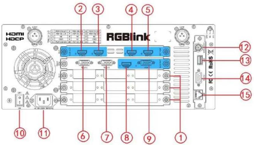
Input Option Slots
| 1 | M2 provides 3 slots to hold 9 single input module options including DVI, USB, CVBS, DP and SDI.DVI-IEach DVI module has one DVI-I input, which can be connected to signals port.VGAEach VGA module has one DB15 input, which can be connected to signals port.HDMIEach HDMI module has one HDMI-A input and one HDMI loop output pc HDMI-A input can be connected to signal from computer. The HDMI loop can be connected to the next M2 or the device with HDMI input port.USBEach USB module has one USB-B input and one USB backup. Access the or mobile hard disk with USB storage function. Support general image and formats.CVSEach CVBS module has one BNC input and one BNC backup. The BNC connected to standard video signal from players and cameras.DPEach DP module has one DP input, which can be connected to signals with port.3G-SDIEach SDI module has one SDI input and one SDI loop output port. The connected to signals from cameras or broadcasting processing device. It alsoconnected to the next M2 or the device with SDI input. |
PGM Output
| 2.3 | HDMIConnect to the display or the LED screen with HDMI connector or patch DVI). |
PST Output
| 4.5 | HDMIConnect to the display with HDMI connector to preset the views. |
PVW Output
| 8 | HDMIConnect to the display with HDMI connector to monitor the signal sources. |
| 9 | VGAConnect to the display or projector which has VGA connector to monitor th sources. (This connector does not support hotplug). |
Control Connectors
| 6.7 | TALLY LightDB15 connectors for Tally light. |
| 12 | GenlockInput signal from the controller or signal generator and other devices. |
| 13 | USBFor custom LOGO, OSD, STILL and MASK saving, and can be loaded. |
| 14 | RS-232For device upgrade. |
| 15 | RJ45For device upgrade. |
Power Connection
| 10 | Power SwitchIlluminated power switch. |
| 11 | Power SocketAC 85-264V, 50/60HZ, MAX 45W, IEC-3 |
1.2.2 Front Panel
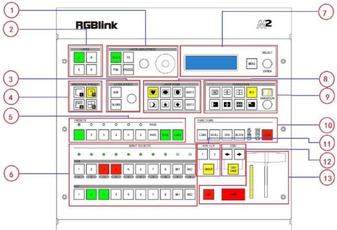
| Panel Instruction | |||
| 1 | Layer adjustment buttons | 8 | MASK buttons |
| 2 | Layer selection buttons | 9 | Transition buttons |
| 3 | Layer effect buttons | 10 | Functions buttons |
| 4 | Multiview presets buttons | 11 | Independent effects switching buttons |
| 5 | Stored presets buttons | 12 | OSD edit buttons |
| 6 | Input source buttons | 13 | Switchers |
| 7 | Menu button and OLED disp | ||
Layer Adjustment Buttons
| 1 | SCALEThis button is used for dimension and crop adjusting. If improper operation can be restored by using RESET.POSThis button is used for position adjusting. If improper operation occurs, it c restored by using RESET.FSScreen parameters setting button. Press the button, its LED light turns on. U choose between full size or screen size.FREEZEFreeze the image or video.Rotary KnobFor dimension and position adjustment and confirmation.Press SCALE button and control the rotary knob to adjust the dimensions.Press POS button and control the rotary knob to adjust the positions.JoystickFor size and position adjustment.Press SCALE and control the joystick to adjust the dimensions.Press POS and control the joystick to adjust the positions. |
Layer Selection Buttons
| 2 | A/B/C/DFor selecting or deleting a layer. The button light is lit when the layer ca off when the layer is deleted, and flashes when the layer can be edited. |
Layer Effect Buttons
| 3 | DSKDSK edit button. User can select a layer and set the parameters for DSK.BLENDBLEND edit button. User can select the layer and set the parameters for ERotary KnobAdjust the alpha of DSK layer.For DSK and BLEND adjustment and confirmation. |
Multiview Presets Buttons
| 4 | Multiview PresetsMultiview mode selection button. The button light is lit when the mode is mainly used for multiview layout settings.1PPIP CENT3P.For 4K2K Mode and Matrix Mode only. |
Stored Presets Buttons
| 5 | SAVESupport 36 saving modes.LOADLoad saved views 1~36.PAGEFor saving or loading, 6 pages in total, and 6 banks for each page.1/2/3/4/5/6These buttons can be used for numeric entry when SAVE or LOAD button |
Input Source Buttons
| 6 | LED IndicatorThe button 1/2/3/4/5/6/7/8 is lit when the signal or background input is ava PGM AreaFor indicating. User cannot change the channel or set the dimension or pos area.BK1/2For indicating. The button is lit when the BK function is enabled.1/2/3/4/5/6/7/8Each button is numbered and can be used as direct numeric entry in settin and dimension.PST AreaFor indicating, the button is lit when PST output signal is in use.For selecting. Press any button to switch the PST signal.For editing.The button light is lit when the channel is in use but cannot be edited;The button light flashes when the channel can be edited;The button light is off when the channel is not selected or available; |
Menu and OLED Display Area
| 7 | MENUCan be used as Return/Exit button.For details, please refer to Understanding the MENU Structure. SELECT/ENTERConfirmation button.OLED DisplayDisplay the current status, menu items and information of the product. |
Layer Mask Buttons
| 8 | Mask Selection Button | |
| Mask selection buttons are shown as follows: | ||
 | Hcart | |
 | Oval | |
 | Round | |
| : Crescent Left: Star: DiamondCUS1/CUS2Mask custom button.Press any mask button, it will enter to the layer mask setting menus. Select set the Mask & PIC Pos X and Y, or set Mask Pos X, Y of Mask or can also load file from U Disk. Refer to Custom EFFECT. | ||
Transition Buttons
| 9 | |
Functions Buttons
| 10 | LOGOEnable or disable the LOGO function. Select “ON”, and user can set the X positions, or load file from U Disk.STILLEnable or disable the STILL function. Select “ON”, and user can set the X positions, or load file from U Disk.OSDEnable or disable the OSD function. Select “ON”, and user can delete thefile from U Disk.BLACKThe button is lit when BLACK function is enabled. BLACK is available fo channel only. Refer to Using Black Out.LOCKLock all buttons on top panel. The button is lit when the buttons on top Press the button again, the button light is off, and the buttons are unlockedIndicatorThe indicator is on when the output format is SD, HD, RGB, 4K1K, 4K2I |
Independent Effects Switching Buttons
| 11 | PGM_OUT1/2 button: Independent effects switching for PGM1 or PGM2.GROUP: Effects switching for PGM1 and PGM2 at the same time.Under the Presentation Group mode, the button is on. PST1 and PST2 can to PGM1 and PGM2 at the same time. |
OSD Edit Buttons
| 12 | OSD←: Subtitle back button.→: Subtitle forward button.OSD TAKESubtitles switch button. |
Switchers
| 13 | CUTSeamless switching. When CUT is used, the transition effect is not displayedTAKESeamless switching with transition effect.T-BARTransition and mix switching. The transition effect can be paused or played pushing T-bar. |
1.2.3 Dimension
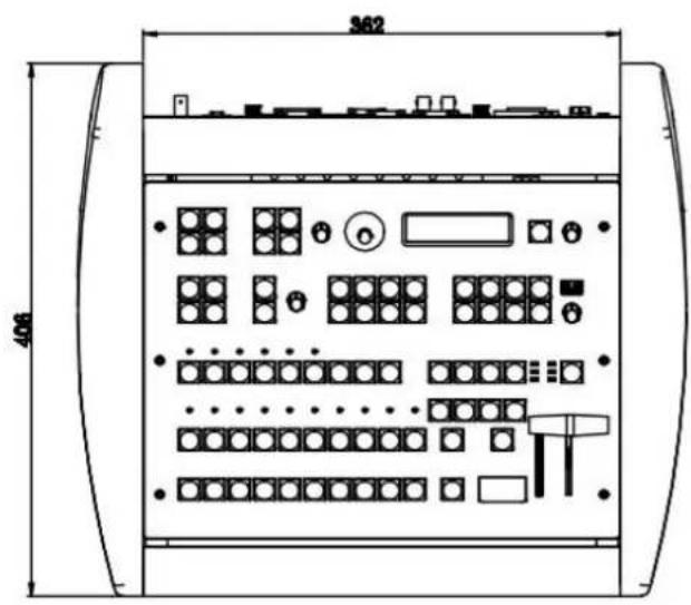
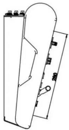
natural_image
Technical line drawing of a mechanical component with dimension annotations (no readable text or symbols)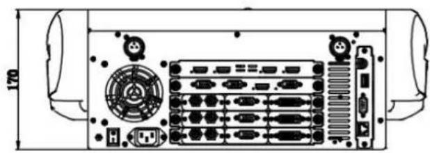
natural_image
Technical line drawing of a server rack with ports and connectors, no text or symbols presentChapter 2 Installing Your Product
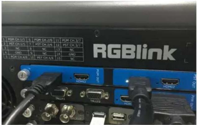
2.1 Plugging in Signals
Connect signals to the product (ensure all devices are powered off first). Tighten connector screws/locks where provided.
2.2 Plugging in Main Power
Connect IEC cable to device and plug into wall socket. Turn on power at wall socket.
2.3 Turning on Your Product
Turn on the power switch on the rear panel.
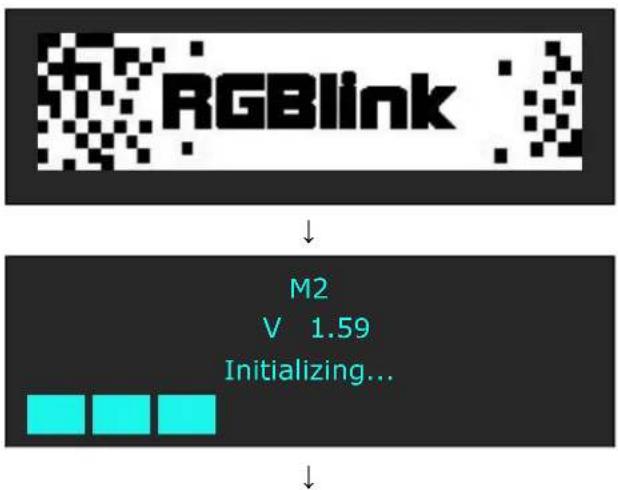
OLED display will show as below, completing initialization before loading the latest settings and input/output configuration.
On delivery, HDMI will be the default input signal, and the output format is 1920x1080x60 by default.
PST Input : HDMI Output Format: 1920×1080@60 System Mode: Normal SN: 0019 Version: 1.59
Chapter 3 Using Your Product
3.1 Using the MENU Button
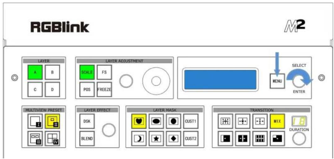
Press the MENU button to display the main menu.
Turn the rotary knob to navigate to the menu item required. If an item is selected, its background turns green. Press the knob to confirm the selection, and set the parameters or check information.
As shown in the figure below:
3.2 Understanding the MENU Structure
The MENU structure is shown in the figure below:
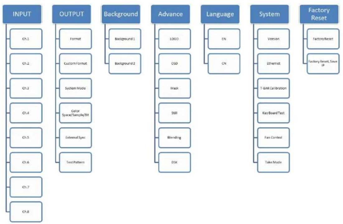
flowchart
graph TD
    A["INPUT"] --> B["Ch.1"]
    A --> C["Ch.2"]
    A --> D["Ch.3"]
    A --> E["Ch.4"]
    A --> F["Ch.5"]
    A --> G["Ch.6"]
    A --> H["Ch.7"]
    A --> I["Ch.8"]
    J["OUTPUT"] --> K["Format"]
    J --> L["Custom Format"]
    J --> M["System Mode"]
    J --> N["Color Space/Sample/Bit"]
    J --> O["External Sync"]
    J --> P["Test Pattern"]
    Q["Background"] --> R["Background 1"]
    Q --> S["Background 2"]
    T["Advance"] --> U["LOGO"]
    T --> V["OSD"]
    T --> W["Mask"]
    T --> X["Still"]
    T --> Y["Blending"]
    T --> Z["DSK"]
    AA["Language"] --> AB["EN"]
    AA --> AC["CN"]
    AD["System"] --> AE["Version"]
    AD --> AF["Ethernet"]
    AD --> AG["T-BAR Calibration"]
    AD --> AH["Key Board Test"]
    AD --> AI["Fan Control"]
    AD --> AJ["Take Mode"]
    AK["Factory Reset"] --> AL["Factory Reset"]
    AK --> AM["Factory Reset, Save IP"]
3.3 Using the Menu
Use the menu system for convenient and intuitive operation. M2 OLED display shows the menu items. The OLED display will show the default state when the menu is not in use, or the operation has timed out. Using the MENU button and rotary knob in the front panel, the OLED display will show the corresponding menus.
3.3.1 Understanding the Display
Turn on the power switch, and the OLED display will show the start-up interface and show the default menu after completing initialization as below:
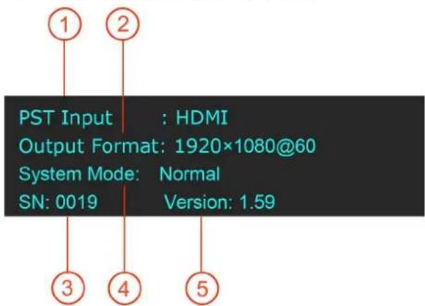
Introduce for the above information:
| 1 | PST InputShow the PST Input signal in use. The related dedicated signal button will |
| 2 | Output FormatShow the output format of the current signal. To configure output resolutionOutput menu. A wide range of resolutions are supported – refer toSpecificIf a # symbol is shown after the resolution, then a custom resolution is b |
| 3 | SNShow the serial number of the product. |
| 4 | System ModeShow the current system mode. |
| 5 | VersionShow the version of the product. |
3.3.2 Understanding the Main Menu
Press the MENU button in the default state and turn the rotary knob, the OLED display will show the main menus as below:
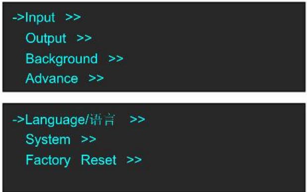
There are 7 menu items in the main menu, and are displayed in 2 pages. Turn the rotary knob, and select any menu above, Press the rotary knob to confirm, the OLED display will show the submenu. Press the MENU button, the OLED display will return to the previous page.
3.3.3 Input Menu
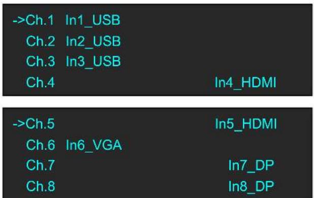
| Ch.1~Ch.8 | Ch.1~Ch.8Select the signal for Ch. 1~Ch. 8. |
| Input FormatShow the input format of Ch. 1~Ch. 8. | |
| Ch.1 Control~Ch.8 ControlIf USB is selected, user can check the information on Input Format, File Number, Play File, Play Mode, Duration of Picture, Order, Play State and USB Upgrade.If HDMI is selected, user can check the information on Input For Name, and set HActive, VActive and Freq.If VGA is selected, user can enable or disable Auto Adjust and Y, Clock and Phase. |
3.3.4 Output Menu
->Format 1920×1080@60
Custom Format >>
System Mode >>
Color Space/Sample/Bit >>
->External Sync >>
Test Pattern >>
| Format | There are 24 kinds of common resolutions. |
| Custom Format | The special display or LED display application may require special settings to meet the requirement--refer to Custom the Output Resolu |
| System Mode | Normal, 4K1K, 4K2K, Matrix, Presentation can be selected. |
| ColorSpace/Sample/Bit | Output PortSelect PST1, PST2, PGM1 or PGM2. |
| DVI/HDMISelect output port as DVI or HDMI. | |
| Bit Depth8 bits and 10 bits are available for DVI;8 bits, 10 bits and 12 bits are available for HDMI. | |
| Color SpaceSelect image or video. | |
| BrightnessBrightness setting, the adjustment range is 0~128. | |
| External Sync | External SyncSelect “ON” or “OFF” will enable or disable external sync function |
| Input FormatShow the input format of external sync. | |
| FormatSet the format of external sync. | |
| Test Pattern | OutputPST or PGM can be selected.Test PatternSelect Color Bar, Solid Color or disable the function.RedRange: 0~255.GreenRange: 0~255.BlueRange: 0~255. |
3.3.5 Background Menu
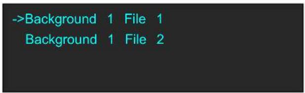
| Background 1/2 | Background 1/2PicturePictureFile 1~14 can be selected.Load from U DiskWhether to load file from U Disk.DeleteDelete the selected fileCapture PictureCapture a picture and save it as File 1~File 50. |
3.3.6 Advance Menu
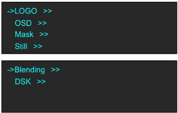
| LOGO | LOGOSelect LOGO 1 or LOGO 2. |
| ON/OFFEnable or disable the LOGO function. | |
| XSet the horizontal position of the LOGO. | |
| YSet the vertical position of the LOGO. | |
| DeleteDelete the selected LOGO. | |
| Load File From U DiskLoad file from U Disk. | |
| OSD | ON/OFFEnable or disable the OSD function. |
| DeleteDelete the OSD. | |
| Load File From U DiskLoad a file from U Disk. | |
| Mask | Mask13 kinds of mode: diamond, round, heart, star, triangle, oval, hexag pentagon, 4 point star, 6 point star, lighting, crescent left and cresce |
| LayerSelect the layer. | |
| ON/OFFEnable or disable the Mask function. | |
| Mask & PIC Pos XSet the horizontal position of mask and picture. | |
| Mask & PIC Pos YSet the vertical position of mask and picture. | |
| Mask Pos XSet the horizontal position of mask. | |
| Mask Pos YSet the vertical position of mask. | |
| PIC Pos XSet the horizontal position of picture. | |
| PIC Pos YSet the vertical position of picture. | |
| Load File From U DiskLoad custom effect image from U Disk. | |
| Still | StillSelect the still. |
| ON/OFFEnable or disable the Still function. | |
| XSet the horizontal position of the still. | |
| YSet the vertical position of the Still. | |
| DeleteDelete the still. | |
| Load File From U DiskLoad a file from U Disk. | |
| Blending | LayerSelect the layer. |
| Blending WidthSet the blending width, the adjustment range is between 1~90. | |
| ON/OFFEnable or disable the Blending function. | |
| DSK | LayerSelect the layer. |
| PresetSelect user, black background, green background, blue background, ro background and white background. | |
| ModeSelect Key In or Key Out. | |
| AlphaThe adjustment range is between 0~128. | |
| Red MinThe adjustment range is between 0~255. | |
| Red MaxThe adjustment range is between 0~255. | |
| Green MinThe adjustment range is between 0~255. | |
| Green MaxThe adjustment range is between 0~255. | |
| Blue MinThe adjustment range is between 0~255. | |
| Blue MaxThe adjustment range is between 0~255. | |
| DSKSelect “ON” or “OFF” to enable or disable DSK function. |
3.3.7 Language Menu
->Language/语言 English
Language/语言 Select Chinese or English.
3.3.8 System Menu
Version >>
Ethernet >>
T-BAR Calibration >>
Key Board Test
Fan Control >>
->Take Mode Swap
| Version | Show the version of COM, PVW MCU, PVW FPGA, PST+PGM PST+PGM FPGA, Optional In 1 MCU, Optional In 1-1 Video, Op 1-2 Video, Optional In 1-3 Video, Optional In 2 MCU, Optional Video, Optional In 2-2 Video, Optional In 2-3 Video, Optional In 3 MCU, Optional In 3-1 Video, Optional In 3-2 Video, Optional In 3-3 Vi |
| Ethernet | Enable or disable the network function. If select “ON”, user can s address, subnet mask and gateway. |
| T-BAR Calibration | Step 1: Press the T-BAR to the top.Step 2: Choose ON.Step 3: Press the T-BAR to the bottom.Step 4: Choose ON. |
| Key Board Test | Enable or disable the LED Light Test function and adjust the key |
| Fan Control | Enable or disable the Auto Speed. Check the current speed and te |
| Take Mode | Swap or Stay can be selected. |
3.3.9 Factory Reset Menu
->Factory Reset >>
Factory Reset, Save IP >>
| Factory Reset | Select “YES” or “NO”. Select “YES” to restore default settings. |
| Factory Reset, Save IP | Select “YES” or “NO”. Select “YES” to restore default settings, but information remains unchanged after reset. |
3.4 PST Mode
M2 can be connected to 2 preview displays with HDMI connectors, and the preview has the functions as below:
3.4.1 Signal Selection
Press any button in Input Sources Area, for example, Press the button [5], the button is lit (yellow), and the signal in PGM monitor will be changed to signal 5.
3.4.2 Add or Delete Layer
Press any button of [A], [B], [C] and [D] in Layer Selection Area to add, delete or change a layer.
When a layer is in use but cannot be edited, the light is lit.
When a layer is selected and can be edited, the light flashes.
When a layer is not in use, the light is off.
Note:
In different system modes, [A]-[D] refers to different layer. Refer to System Mode.
3.4.3 Freeze the Layer
(1) Freeze a PST layer
Press the FREEZE button, and the layer displaying in PST will be frozen. User can use CUT, TAKE or T-BAR to swap the frozen layer to PGM. Press the FREEZE button again, and the frozen layer in PST becomes live again. The FREEZE function does NOT happen to PST and PGM synchronously.
(2) Freeze a PGM layer
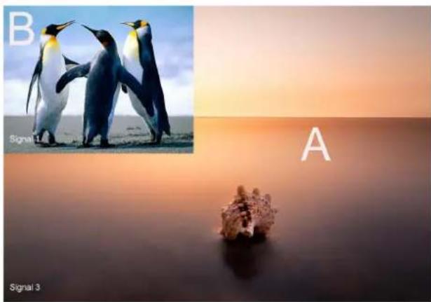
Take PIP (two layers) for example. Follow the steps as below:
- Press the shortcut button to enable multiview (PIP);
- Select the signal source for the background layer and sublayer;
- Use CUT, T-bar or TAKE to swap the PIP to PGM;
natural_image
Composite image showing penguins in two scenes: one at sunset with a rock, the other at sunset with a penguin (no text or symbols)- Press the lit button in PGM area. The layers in PGM are also displayed in PST, synchronously;
- Select layer [A] or [B];
- Press the FREEZE button, the selected layer is frozen in both PST and PGM displays, synchronously;
- Press the FREEZE button again, and the frozen layer will become live.
3.4.4 Multiview Presets
- Press any button in Multiview Presets Area to select multiview layouts, including 1P, PIP CENT, and 3P.
- User can adjust the position, dimension for the selected layer, and set DSK, BLEND and MASK.
3.4.5 Set the Position
-
Press any button of [A]-[D] in Layer Selection Area, the light flashes when the layer is selected and can be edited;
-
Press the POS button in Layer Adjustment Area, and enter to the menus as follows:
->H Pos 120
V Pos 329
Reset >>
Use the rotary knob or joystick to adjust the position of the layer.
Push the joystick to the left or right, the horizontal position will be changed.
Push the joystick up or down, the vertical position will be changed.
If improper operation occurs, it can be restored by using RESET.
3.4.6 Scale and Crop the Layer
- Press any button of [A] to [D] in Layer Selection Area, the light flashes when the layer is selected.
- Press the SCALE button in Layer Adjustment Area, and enter to the menus as follows:
->H Size 1920
V Size 1080
Reset >>
Crop >>
Use the rotary knob or joystick to adjust the size of the layer.
Push the joystick to the left or right, the horizontal size will be changed.
Push the joystick up or down, the vertical size will be changed.
If select
Crop H Pos: Crop the horizontal position.
Crop V Pos: Crop the vertical position.
Crop H Size: Crop the horizontal size.
Crop V Size: Crop the vertical size.
Crop Reset: If improper operation occurs, it can be restored by using RESET.
3.4.7 DSK Settings
- Firstly, enable the multiview function. DSK is used in multiview only.
- Press MENU button, and enter to the menu items. Turn the rotary knob, and select
option in , Press the knob to confirm. (Or Press the DSK button to enter to the DSK menu items)
->Layer Layer 1
Preset Black Background
Mode Key In
Alpha 128
->Red Min 0
Red Max 208
Green Min 0
Green Max 208
->Blue Min 0
Blue Max 208
DSK ON
Layer: Select the target layer for DSK.
Preset: Select user, black background, green background, blue background, red background or white background.
Mode: Select Key In or Key Out.
Alpha: The adjustment range is between 0\~128.
Red Min: The adjustment range is between 0\~255.
Red max: The adjustment range is between 0\~255.
Green Min: The adjustment range is between 0\~255.
Green Max: The adjustment range is between 0\~255.
Blue Min: The adjustment range is between 0\~255.
Blue Max: The adjustment range is between 0\~255.
DSK: Can select enable or disable the DSK function.
Instructions
Key In
To cut out the color selected in [Preset] and other colors remain unchanged. Take Black Background and Blue Background for example, see the effect below:


Key Out
The color selected in [Preset] remains unchanged and other colors are cut out. Take Black Background and Blue Background for example, see the effect below:
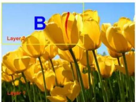

User
In addition, User can select [User] in [Preset], which allows user to custom the color value by setting Red Min, Red Max, Green Min, Green Max, Blue Min and Blue Max values.
Note:
√ DSK applies to the Normal Mode only;
√ The cutout will display the overlapped picture of the background layer (Layer 2);
3.4.8 BLEND Settings
- Firstly, enable the multiview function.
- Press MENU button, and enter to the menu items. Turn the rotary knob, and select
option in , Press the knob to confirm. (Or Press the BLEND button to enter to the BLEND menu items)
->Layer Layer 1
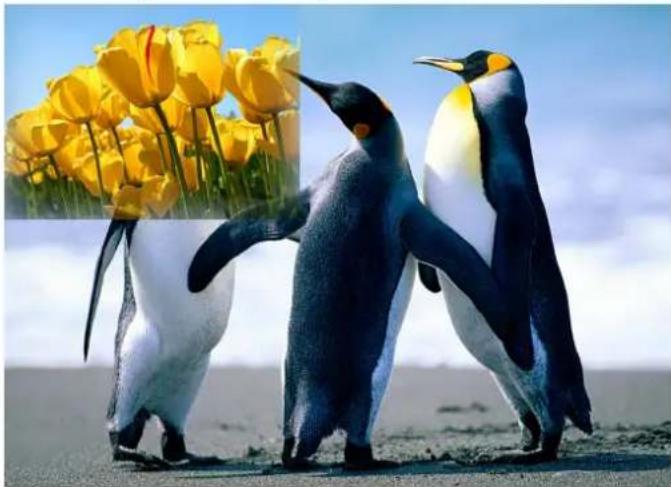
Blending Width 50
ON/OFF ON
Layer: Select the target layer for BLEND.
Blending Width: Blending width setting, the adjustment range is between 1\~90.
ON/OFF: Enable or disable the blending function.
For example, set the Blending Width as 50, see the effect below:
natural_image
Two penguins standing on a sandy beach with yellow tulips in the background (no text or symbols)3.4.9 Mask Settings
- Press the MENU button, and enter to the menu items.
- Turn the rotary knob, and select
option in , Press the knob to confirm:
Enable the mask function:
Turn the rotary knob, select
Select mask:
Turn the rotary knob, and select
User can also Press the layer mask selection button in Layer Mask Area to select a mask.
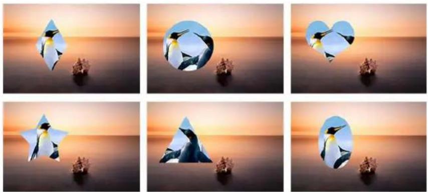
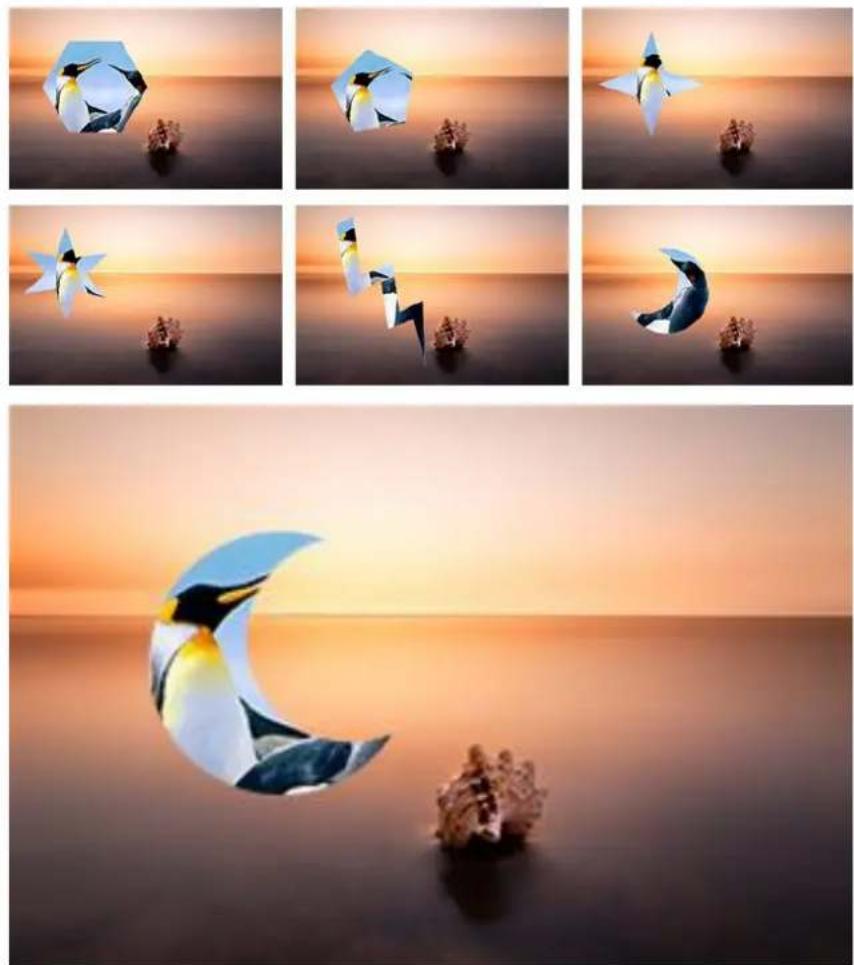
Mask settings:
The MASK shortcut button can be used as a shortcut button to enlarge the mask. For each MASK button, 6 dimensions are available. Press a shortcut button, press it again and the mask will be enlarged. User can press the shortcut button for 6 times consecutively at most to enlarge a mask. The 7^th pressing will disable the MASK function.
Custom buttons:
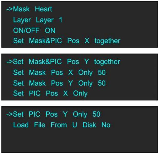
There are 2 custom buttons in Layer Mask Area, Press [CUST1] or [CUST2], for example, Press [CUST1], it will enter to the menus as follows:
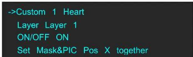
Turn the rotary knob, and select
Then Press the [CUST1] button, the custom will change to the mask set, as shown below:
->Custom 1 Star
Layer Layer 1
ON/OFF ON
Mask&PIC Pox X 50
Set a Mask:
User can set the H position, V position, H size, V size of Mask and/or PIC. In addition, user can load custom masks by U Disk. Refer to the Custom EFFECT.
3.4.10 Transition Settings
- Press the transition buttons in Transition Area, M2 has 14 kinds of wipe modes:
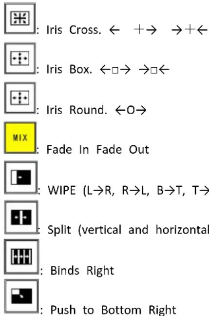
- Press the TAKE button, or use T-bar switcher to switch the image to program with selected wipe. Using CUT does NOT display the transition effect.
3.4.11 Adjust R,G,B of SDI,VGA,CVBS,USB Input
M2 of Version 2.13 allows users to adjust the value of RGB of SDI, VGA, CVBS, USB input.
PST Input :VGA
Output Format:1920x1080@60
System Mode : Normal
SN:0229 Version:2.13
Here are the operation.
Enter Menu of Input
->Input >>
Output >>
Background >>
Advance >>
Find the Chanel of SDI, VGA, CVBS or USB. Users can preview the input from the output display. For example, SDI input in Chanel 8.
Ch.5 IN5_DVI
Ch.6 IN6_HDMI
Ch.7 IN7_HDMI
->Ch.8 IN8_SDI
Enter Chanel 8 and find Ch.8 Control
Ch.8 IN8_SDI
Input Format 1280x720@60
->Ch.8 Control >>
Enter Ch.8 Control menu, there are items to adjust R,G,B
Brightness R,G,B Value range from 0 to 100
Contrast range from 0 to 100
Saturation rang from 0 to 100
Sharpness range from 0 to100
Color Temp R,G,B value range from 0 to 255
3.5 System Mode
3.5.1 Normal
(1) Press the MENU button and enter to the menu items. Turn the knob and select
Input >>
Output >>
Background >>
Advance >>
(2) Press the knob to confirm. Turn the knob, select
Format >>
Custom Format >>
->System Mode >>
Color Space/Sample/Bit >>
Note:
√ In 1P, [A] refers to the background layer, [B], [C] and [D] have no functions.
√ In 2P, [A] refers to the background layer, [B] refers to the sublayer; [C] and [D] have no function.
√ In 3P, [A] refers to the background layer, [B] and [C] are the sublayers; [D] has no function.
3.5.2 4K1K
1. Normal Mode
(1) Press MENU button, enter to the menu items. Turn the knob and select
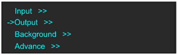
(2) Press the knob to confirm. Select <4K1K> under
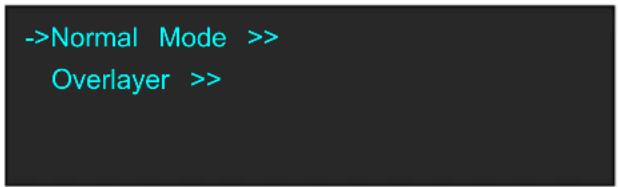
(3) Select
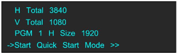
(4) Select a layout:
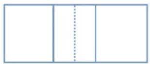
natural_image
Simple geometric diagram with three vertical rectangles and a dashed line through the center (no text or symbols)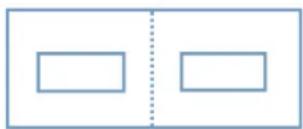
natural_image
Simple diagram with two empty rectangular boxes separated by a vertical dotted line (no text or symbols)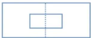
natural_image
Simple geometric diagram with a rectangle and vertical dashed line (no text or symbols)In the left mode, when
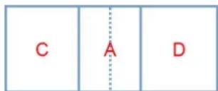
When
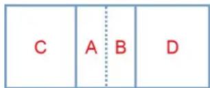
In the middle mode, when
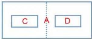
flowchart
graph TD
    C["C"] --> A["A"]
    D["D"] --> A
    style A stroke-dasharray: 5 5
When
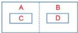
flowchart
graph TD
    A["A"] --> C["C"]
    B["B"] --> D["D"]
    style A fill:#fff,stroke:#000
    style B fill:#fff,stroke:#000
    style C fill:#fff,stroke:#000
    style D fill:#fff,stroke:#000
In the right mode, when
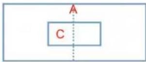
When
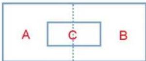
2. Overlayer
(1) Press the MENU button and enter to the menu items. Turn the knob and select
Input >>
->Output >>
Background >>
Advance >>
(2) Press the knob to confirm. Turn the knob, select <4K1K> under
Normal >>
->4K1K >>
4K2K >>
Matrix >>
(3) Select
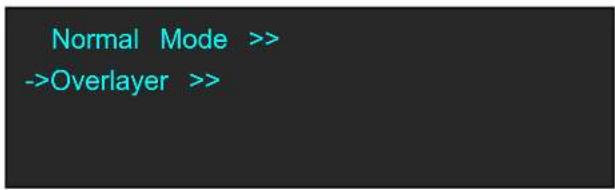
(4) Set the overlayer width (for example, 200), select
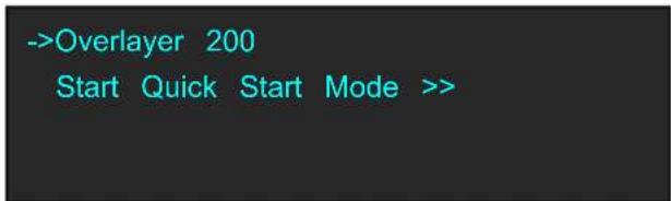
Note:
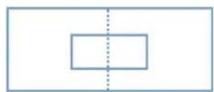
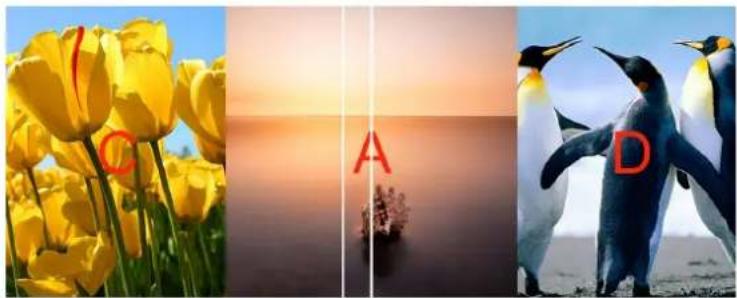
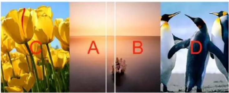
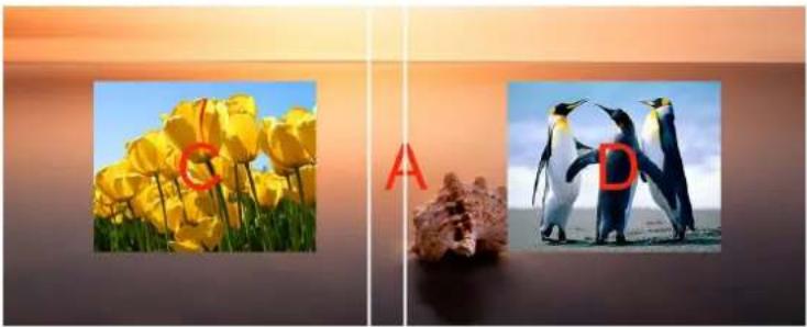
Overlayer width refers to the width of the overlapped part of two layers (two ports).
(5) Select a background layout mode:
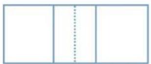
natural_image
Simple geometric diagram with three vertical lines and a dashed line, no text or symbols present.Layout1
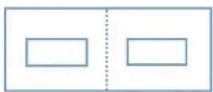
natural_image
Two empty rectangular boxes separated by a vertical dotted line (no text or symbols)Layout2
natural_image
Simple geometric diagram with a rectangle and dashed vertical line (no text or symbols)Layout3
In Layout 1, when
natural_image
Three-panel image showing yellow tulips at sunset, a penguin photo with red letter 'A', and a penguin photo labeled 'D' (no text or symbols on the images themselves)When
natural_image
Three-panel image showing yellow tulips, a close-up of penguins at sunset, and a close-up of a penguin (no text or symbols)In Layout 2, when
natural_image
Two photos of yellow tulips and penguins on a beach, separated by a red letter 'A' (no text or symbols in the images themselves)When
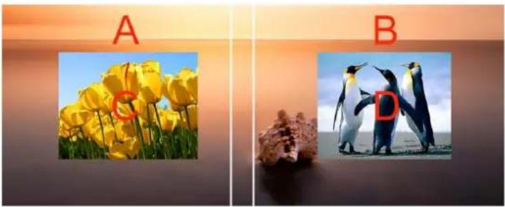
natural_image
Two side-by-side photos labeled A and B showing yellow tulips and penguins on a beach, with no text or symbols beyond labels.In Layout 3, when
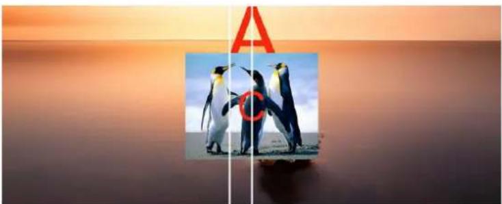
natural_image
Two penguins standing on a beach at sunset, one with a red letter 'A' and the other with a red circle (no text or symbols on the penguin image)When
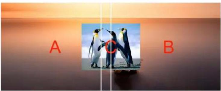
3.5.3 4K2K
(1) Press the MENU button, enter to the main menu. Turn the knob and select
Input >>
->Output >>
Background >>
Advance >>
(2) Press the knob to confirm. Turn the knob, select <4K2K> under
Normal >>
4K1K >>
->4K2K >>
Matrix >>
(3) Set the parameters:
->H Total 3840
V Total 2160
PGM1 H Size 1920
PGM1 V Size 1080
->Set YES
Note:
√ 4P is available for 4K2K and Matrix only.
√ In 4K2K mode, [A]-[D] refers to one of the four output port (PGM1, PGM2, PST1 and PST2).
√ In 4K2K mode, OSD, MASK, STILL, DSK and Blend are not available.
3.5.4 Matrix
(1) Press the MENU button, enter to the main menu. Turn the knob and select
Input >>
->Output >>
Background >>
Advance >>
(2) Press the knob to confirm. Turn the knob, select
Normal >>
4K1K >>
4K2K >>
->Matrix >
Matrix is used to assign signals. [A]-[D] refers to the 4 output ports (PGM1, PGM2, PST1 and PST4). Select the channel first, and select signal source in the PST area. Any signal source can be assigned to each output port.
3.5.5 Presentation
(1) Press the MENU button, enter to the main menu. Turn the knob and select
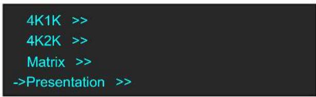
(3) Under Presentation, users can choose Presentation 2K1K and Presentation Group. OLED will show as follow:
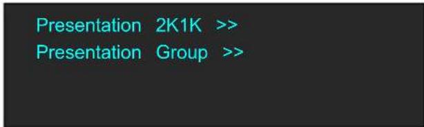
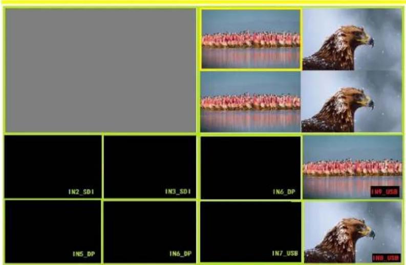
(4) Presentation 2K1K mode allows 1 output displays 4 layers as the following example.
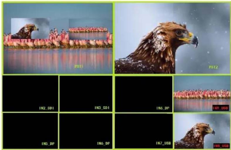
(5)Presentation Group mode allows PGM1 and PGM2 to be switched at the same time. Layers A,B,C are on PST1 and Layer D on PST2. When PST1 is selected, users can change the input source and layout of Layer A,B,C and switch to PGM1 by TAKE button or T-Bar. When PST2 is selected, users can change input source and layout of Layer D and switch to PGM2 by TAKE or T-Bar. Under the Presentation Group mode, PST1 and PST2 are switched to PGM1 and PGM2 by TAKE button at the same time. Please note that T-Bar doesn't work under Presentation Group mode.
natural_image
Composite image showing a bird head in flight over water, with multiple grayscale panels below each panel labeled IN2_SD1 to IN7_USB.3.6 Switching Layers
User can use T-bar, CUT or TAKE to switch layers between PGM and PST.
T-bar: Switch the PST layer PST to PGM; user can set the transition duration. The transition effect can be paused or played back by pushing T-bar.
CUT: Quick seamless transition. Transition effect is NOT displayed.
TAKE: A button to switch layers between PGM and PST. The transition effect is displayed.
Note:
There are two TAKE modes: SWAP and STAY. Follow the steps as below:
(1) Press the MENU button, turn to Page 2:
Language EN
->System >>
Factory Reset >>
(2) Select
Version >>
Ethernet >>
T-BAR Calibration >>
Key Board Test
Fan Control >>
->Take Mode Swap
(3) Turn to Page 2, select [Take Mode].
If SWAP is selected, the PST layer and PGM layer is swapped after pressing the CUT, TAKE button or using T-bar.

natural_image
Two penguins standing on a beach with yellow tulips in the foreground, no visible text or symbols
natural_image
Silhouettes of people playing on a beach at sunset, with the word 'PGM' overlaid (no other text or symbols)After Switching

natural_image
Silhouettes of people playing beach at sunset with 'PST' text overlay (no other signage or symbols)
natural_image
Two penguins standing on a beach with yellow tulips in the foreground, labeled 'PGM' at bottom (no other text or symbols)If STAY is selected, the PST layer and PGM layer are the same even after pressing the CUT, TAKE button or using T-bar. The PST layer can be edited independently. After another switch, the PGM layer is the same with PST layer.

natural_image
Two penguins standing on a beach with yellow tulips in the foreground, labeled 'PST' in the corner (no other text or symbols)
natural_image
Silhouettes of people on a beach at sunset with the word 'PGM' overlaid (no other text or symbols)After Switching

natural_image
Two penguins standing in the sky above yellow tulips, with 'PST' watermark visible (no other text or symbols)
natural_image
Two penguins standing on a beach with yellow tulips in the foreground, labeled 'PGM' at bottom (no other text or symbols)3.7 Background Picture
3 sources can be used as the background picture of M2, they are input source, captured picture, and picture file loaded with U Disk.
3.7.1 Input Source
User can use an input source as the background picture. For example, user can connect the device to a computer, and the current input can be used as the background.
3.7.2 Captured Picture
(1) Press the MENU button and enter to the menu items; turn the knob and select
Input >>
Output >>
->Background >>
Advance >>
(2) Select
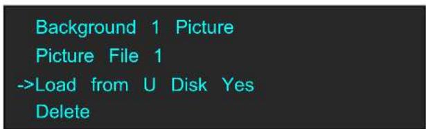
->Background 1 File 1
Background 1 File 2
Background 1 Picture
Picture File 1
Load from U Disk No U Disk
Delete
->Capture Picture >>
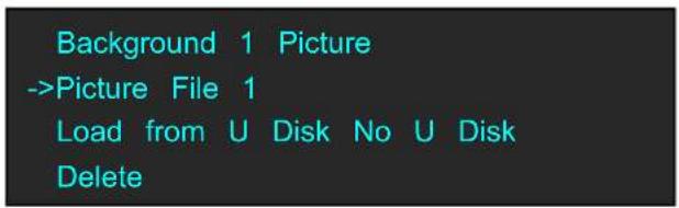
User can name the captured picture as File 1\~14. Take File 1 for example. Press the knob to capture the picture. After capturing, select
3.7.3 Picture file loaded with U Disk
The background picture can be a picture loaded with U Disk. See below:
Before loading a picture:
√ The maximum resolution is 1920 × 1080 ;
√ The picture format MUST be BMP;
√ It should be named as IMAGE_1\~IMAGE_50.
When the resolution meets the criteria
When the picture resolution meets the criteria above, user just needs to change the picture format into BMP. Right click the picture, select
When the resolution does NOT meet the criteria
For example, the resolution of a screen is 3800 × 1000 , user needs to cut the picture into halves (vertical). Follow the steps as below:
(1) Open Photoshop;
(2) Click
(3) Select
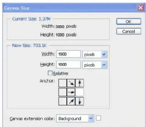
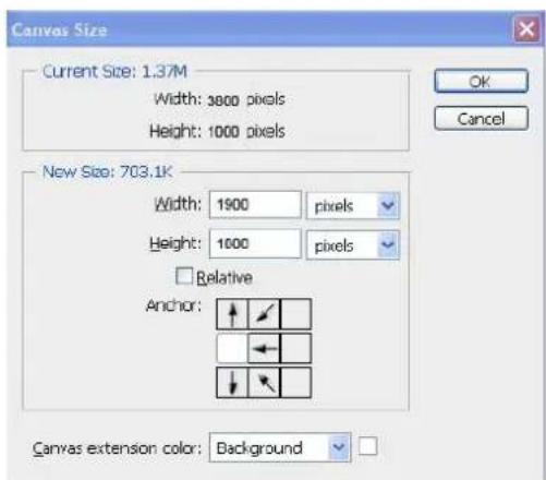
(5) Click OK, a dialog reading "The new canvas size is smaller than the current canvas; some clipping will occur" will pop up. Click PROCEED.
(6) Save the two halves as BMP pictures, and name them as IMAGE_1 and IMAGE_2 respectively.
Importing the pictures
The pictures can be loaded in two ways, see below:
1. By U Disk
Save IMAGE_1 and IMAGE_2 in the U Disk;
Insert the U Disk in the TF card or the USB control connector on the rear panel;
Note:
√ U Disk format: FAT32;
√ The folder should be named M2 in the root directory, which contains IMAGE_1 and IMAGE_2;
2. By TF card
Use card reader to write the images in the FT card (folder: IMAGE) in the PGM board.
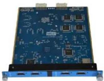
natural_image
Blue printed circuit board with multiple ports and connectors (no visible text or symbols)Set as background
If the resolution meets the criteria, follow the steps as below:
(1) Select
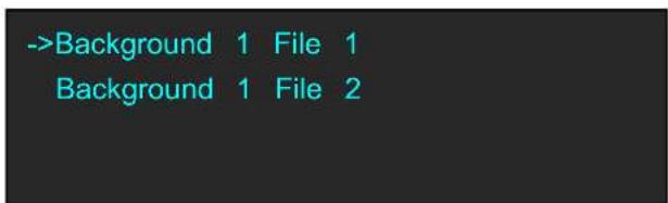
(2) Press
(3) Press the BK1 or BK2 in the PST area, and select Background 1→File 1 or Background 2→File 2. Save the settings.
If the resolution does not meet the criteria. For example, the required resolution is 3800 × 1000 .
Follow the steps as below:
(1) Press the MENU button, select
Input >>
->Output >>
Background >>
Advance >>
(2) Select
Format 1920×1080@60
Custom Format >>
->System Mode >>
Color Space/Sample/Bit >>
(3) Select
->Normal Mode >>
Overlayer >>
H Total 3800
V Total 1000
PGM 1 H Size 1900
->Start Quick Start Mode >>
(4) Press
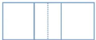
natural_image
Simple geometric diagram with three vertical lines and a dashed line, no text or symbols present.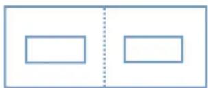
natural_image
Two empty rectangular boxes separated by a vertical dotted line (no text or symbols)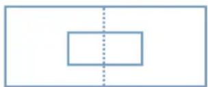
natural_image
Simple geometric diagram with a rectangle and dashed vertical line (no text or symbols)(5) Select any of the layouts, select
->One Input Two Outputs >>
Two Inputs Two Outputs >>
(6) Press the BK1 or BK2 in the PST area, and select Background 1 File 1 or Background 2 File 2. Save the settings.
3.8 Set the Output Resolution
3.8.1 Select the Output Resolution
- Press the MENU button, and enter to the menu items, turn the rotary knob and select
Input >>
->Output >>
Background >>
Advance >>
- Press the rotary knob to confirm, and enter to the menus as below:
->Format 1920×1080@60
Custom Format >>
System Mode >>
Color Space/Sample/Bit >>
is the default option. Press the rotary to confirm. Turn the rotary knob, select the output resolution according to actual need.
3.8.2 Custom the Output Resolution
- Press the MENU button, and enter to the menu items, turn the rotary knob and select
Input >>
->Output >>
Background >>
Advance >>
- Press the rotary knob to confirm, and enter to the menus as below:
->Format 1920×1080@60
Custom Format >>
System Mode >>
Color Space/Sample/Bit >>
- Turn the rotary knob, and select
, press the rotary knob to confirm.
Format 1920×1080@60
->Custom Format >>
4K1K >>
Color Space/Sample/Bit >>
↓
->H Active 1024
V Active 768
Freq 60
Set Yes
- Set H Active, V Active and Fred according to actual need, then select
and set "Yes", Press the rotary knob to confirm.
3.9 Using Black Out
Black out description:
One-key touch to black out the display
M2 provides BLACK effect processing for PGM and PST, with instant BLACK effect. Operation is as below:
Press the BLACK button, the button light is lit, and the PGM display is blacked out.
The effect is shown as below:

natural_image
Two penguins standing on a beach with yellow tulips in the foreground (no text or symbols visible)
natural_image
Solid dark gray image with no visible content, text, or symbols.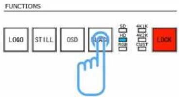
3.10 Saving Views
M2 provides 36 banks for saving or recording parameters. To save the current parameters and settings:
- Press the SAVE button in Stored Presets Area, the SAVE and PAGE button lights are lit, and some of buttons 1\~6 are lit and some are flashing.
If the button is lit, it is available for saving. If the button flashes, that means it's already occupied, and can be overwritten.
SAVE TO
->PAGE: 1
BANK: 1
Backup To U Disk No U Disk
- Select PAGE, for example, the button [2] is lit, press the button [2].
SAVE TO
->PAGE: 2
BANK: 1
Backup To U Disk No U Disk
- After setting the PAGE, it will jump to BANK option, for example, the button [2] is lit, press the button [2]:
SAVE TO
PAGE: 2
->BANK: 2
Backup To U Disk No U Disk
- Press the SAVE button again, the button light is off, and exit the SAVE function.
- Select
, user can save the parameters to the U Disk.
3.11 Recall Saved Settings
M2 provides 36 banks for saving or recording parameters. To recall saved settings:
- Press the LOAD button in Stored Presets Area, the button lights of LOAD and PAGE are lit, and some of buttons 1\~6 are lit and some are flashing. The button lit is ready for recall and the button flashing means it's being recalled. Press the button lit to recall.
LOAD FROM
->PAGE: 1
BANK: 1
Load From U Disk No U Disk
- Select PAGE, for example, the button [2] is lit, press the button [2].
LOAD FROM
->PAGE: 2
BANK: 1
Load From U Disk No U Disk
- After setting the PAGE, it will jump to BANK option, for example, the button [2] is lit, press the button [2]:
LOAD FROM
PAGE: 2
->BANK: 2
Load From U Disk No U Disk
-
Press the LOAD button again, the button light is off, and exit the LOAD function.
-
Select
, user can load the saved parameters from the U Disk.
Note:
In Normal mode, data can be only loaded to PST without affecting PGM. It's convenient for users to save data in advance, and fast recall and transition can be achieved as needed.
4.1 Product
210-3072-02-0 M2
4.2 Options
4.2.1 Input Options
190-0001-02-1 VGA Input
1× VGA
190-0001-03-1 Display Port Input (DP1.0)
1 × Display Port
190-0001-04-1 DVI Input
1 × DVI
190-0001-06-1 HDMI Input /Loop Out
1 × HDMI (with loop)
190-0001-07-1 3G-SDI Input /Loop Out
1 × SDI (with loop)
190-0001-09-1 CVBS In/Backup
1 × CVBS + CVBS BACKUP
190-0001-10-1 USB In/Backup
1 × USB + USB BACKUP
4.2.2 Accessories
980-0001-01-3 EXT3 Module (Support for 3 Input modules)
290-3072-01-0 Wings/Sides for M2
980-0006-01-0 LED Goose neck Lamp (Single)
5.1 Contact Us

Web
www.rgblink.com
Phone
+86-592-577-1197
Sales
Support
sales@rgblink.com
support@rgblink.com
Social Media

@RGBLINK

/rgblink

+rgblink

/rgblink

rgblink

rgblink
6.1 Specification
| DVI Input (DVI optional module) | |
| Interface Appearance | 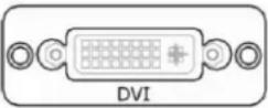 |
| Board Size | 52(L)×19.5(W) (mm) |
| Number of Inputs | 9 |
| Connector | Standard DVI-I socket |
| Supported Resolution | SMPTE: 625/25/50 PAL, 525/29.97/59.94 NTSC,1080P50/59.94/60, 720p50/59.94/60VESA: 800×600@60 | 1024×768@60 | 1280×1024@60 |1600×1200@60 | 1920×1080@60 | 1920×1200@60 | 2048×1152@ |
| Signal Level | TMDS pwl, single pixel input,165MHz bandwidth |
| Format Standard | HDMI 1.3 |
| VGA Input (VGA optional module) | |
| Interface Appearance | 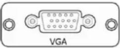 |
| Board Size | 52(L)×19.5(W) (mm) |
| Number of Inputs | 9 |
| Connector | Standard DB15 Socket |
| Supported Standard | VGA-UXGA |
| Signal Level | R, G, B, Hsync, Vsync: 0 to1Vpp±3dB (0.7V Video+0.3v SyncBlack level: 300mV Sync-tip: 0V |
| Supported Resolution | VGA-UXGA (800×600@60 | 1024×768@60 | 1280×1024@60 |1440×900@60 | 1600×1200@60) |
| DP Input (DP optional module) | |
| Interface Appearance | 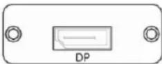 |
| Board Size | 52(L)×19.5(W) (mm) |
| Number of Inputs | 9 |
| Connector | Standard |
| Supported Resolution | VESA: 3840×2160×24 | 3840×2160×25 | 3840×2160×30 |4096×2160×24SMPTE: 625/25/50 PAL, 525/29.97/59.94 NTSC,1080P50/59.94/60 | 1080i50/59.94/60, 720p50/59.94/60 |
| Supported Bandwidth | 21.6Gb/s |
| Format Standard | DP1.0 |
| CVBS Input (CVBS optional module) | |
| Interface Appearance | 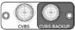 |
| Board Size | 52(L)×19.5(W) (mm) |
| Number of Inputs | 9 |
| Connector | Standard BNC Socket |
| Supported Standards | PAL/NTSC |
| Signal Level | 1Vpp±3db (0.7V Video+0.3v Sync) 75 ohm |
| Multiplex | 480i, 576i |
| USB Input (USB optional module) | |
| Interface Appearance | 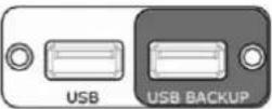 |
| Board Size | 52(L)×19.5(W) (mm) |
| Number of Inputs | 9 |
| Connector | Standard USB port |
| Supported Standard | Support general Image and video formats |
| 3G-SDI Input (SDI optional module) | |
| Interface Appearance | 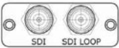 |
| Board Size | 52(L)×19.5(W) (mm) |
| 3G-SDI Input | |
| Number of Inputs | 9 |
| Connector | Standard BNC Socket |
| Data Rate | 2.97Gb/s, 2.97/1.001Gb/s, 1.485Gb/s, 1.485/1.001Gb/s and 270Mb/s |
| Supported Standard | SMPTE 425M - 3G Level and Level B |
| Supported Resolution | SMPTE 425M (3G Level A) 4:2:2: 1920×1080/60 (1:1) | 1920×1080/50 (1:1).SMPTE 425M (3G Level B DS1 and DS2) 4:2:2: 1920×1080/60 (1:1)1920×1080/50 (2:1)SMPTE 296M (HD): 1280×720/50 (1:1) | 1280×720/50 (1:1)SMPTE 125M (SD): 1440×487/60 (2:1) | 525-line 487 genericSMPTE ITU-R BT.656 (SD): 1440×576/50 (2:1), 625-line generic. |
| Balance | Belden 1694A cable:150m at 2.97Gb/s250m at 1.485Gb/s480m at 270Mb/s |
| SDI Loop Out | |
| Number of Loop Ou | 9 |
| Connector | Standard BNC Socket |
| Data Rate | 2.97Gb/s, 2.97/1.001Gb/s, 1.485Gb/s, 1.485/1.001Gb/s and 270Mb/s |
| Supported Standard | SMPTE 425M - 3G Level A and Level B |
| Supported Resolution | SMPTE 425M (3G Level A) 4:2:2: 1920×1080/60 (1:1) | 1920×1080/50 (1:1).SMPTE 425M (3G Level B DS1 and DS2) 4:2:2: 1920×1080/60 1920×1080/50 (2:1)SMPTE 296M (HD): 1280×720/50 (1:1) | 1280×720/50 (1:1)SMPTE 125M (SD): 1440×487/60 (2:1), 525-line 487 genericSMPTE ITU-R BT.656 (SD): 1440×576/50 (2:1), 625-line generic. |
| Balance | Belden 1694A cable:150m at 2.97Gb/s250m at 1.485Gb/s480m at 270Mb/s |
| HDMI IN+HDMI LOOP (HDMI optional module) | |
| Interface Appearance | 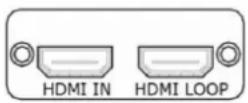 |
| Board Size | 52(L)×19.5(W) (mm) |
| HDMI Input | |
| Number of Inputs | 9 |
| Connector | Standard HDMI-A socket |
| Supported Resolution | SMPTE: 625/25/50 PAL, 525/29.97/59.94 NTSC, 1080P50/59.94/60 | 1080i50/59.94/60, 720p50/59.94/60VESA: 800×600@60 | 1024×768@60 | 1280×720@60 | 1280×800 1280×960@60 | 1280×1024@60 | 1400×1050@60 | 1600×1200@6 1920×1080@60 | 1920×1200@60 | 2048×1152@60 |
| Signal Level | TMDS pwI, single pixel input, 165MHz bandwidth |
| Format Standard | HDMI 1.3 |
| HDMI Loop Out | |
| Number of Loop Out | 9 |
| Connector | HDMI standard type A interface |
| Supported Resolution | SMPTE: 625/25/50 PAL, 525/29.97/59.94 NTSC, 1080P50/59.94/60 | 1080i50/59.94/60, 720p50/59.94/60VESA: 80O×600@60 | 1024×768@60 | 1280×720@60 | 1280×800 1280×960@60 | 1280×1024@60 | 1400×1050@60 | 1600×1200@6 1910×1080@60 | 1920×1200@60 | 2048×1152@60 |
| Format Standard | HDMI 1.3 |
| HDMI PGM Output | |
| Number of Outputs | 2 |
| Connector | HDMI standard type A interface |
| Supported Resolution | SMPTE: 625/25 PAL, 525/29.97 NTSC, 625/50p PAL, 525/59.94p NTSC,720p50/59.94/60 | 1080i50/59.94/60 | 1080P50/59.94/60VESA: 800×600@60 | 1024×768@60 | 1280×768@60 | 1280×1024@60 | 1600×1200@60 | 1920×1080@60 | 1920×1080@ |
| Format Standard | HDMI 1.3 |
| HDMI PST Output | |
| Number of outputs | 2 |
| Connector | HDMI standard type A interface |
| Supported Resolution | SMPTE: 625/25 PAL, 525/29.97 NTSC, 625/50p PAL, 525/59.94p NTSC,720p50/59.94/60 | 1080i50/59.94/60 | 1080P50/59,94/60VESA: 800×600@60 | 1024×768@60 | 1280×768@60 | 1280×1024@60 | 1600×1200@60 | 1920×1080@60 | 1920×1080@) |
| Format Standard | HDMI 1.3 |
| HDMI PVW Output | |
| Number of outputs | 1 |
| Connector | HDMI standard type A interface |
| Supported Resolution | SMPTE: 625/25 PAL, 525/29.97 NTSC, 625/50p PAL, 525/59.94p NTSC,720p50/59.94/60 | 1080i50/59.94/6O | 1080P50/59.94/60VESA: 800×600@60 | 1024×768@60 | 1280×768@60 | 1280×1024@60 | 1600×1200@60 | 1920×1080@6O | 1920×1080@50 |
| Format Standard | HDMI 1.3 |
| VGA PVW Output | |
| Number of outputs | 1 |
| Connector | Standard DB15 Socket |
| Supported Resolution | VESA: 800×600@60 | 1024×768@60 | 1024×768@75 | 1280×768 1280×1024@60 | 1440×900@60 | 1400×1200@60 | 1600×1200@6 1920×1080@60 | 1920×1200@60 | 2048×1152@60 |
| Signal Level | R, G, B, Hsync, Vsync:0 to1Vpp±3dB (0.7V Video+0.3v Sync)Black level: 300mV Sync-tip: 0V |
TALLY Pin Definition
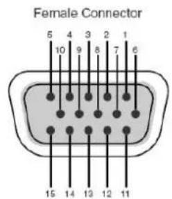
TALLY 1
| Pin No. | Channel |
| 1 | PGM Ch.1 |
| 2 | PST Ch.1 |
| 3 | NC |
| 4 | GND |
| 5 | PGM Ch.4 |
| 6 | PGM Ch.2 |
| 7 | PST Ch.2 |
| 8 | NC |
| 9 | NC |
| 10 | PST Ch.4 |
| 11 | PGM Ch.3 |
| 12 | PST Ch.3 |
| 13 | NC |
| 14 | GND |
| 15 | NC |
TALLY 2
| Pin No. | Channel |
| 1 | PGM Ch.5 |
| 2 | PST Ch.5 |
| 3 | NC |
| 4 | GND |
| 5 | PGM Ch.8 |
| 6 | PGM Ch.6 |
| 7 | PST Ch.6 |
| 8 | NC |
| 9 | NC |
| 10 | PST Ch.6 |
| 11 | PGM Ch.7 |
| 12 | PST Ch.7 |
| 13 | NC |
| 14 | GND |
| 15 | NC |
PIN9 NC (No Connection) avoid to be plugged by VGA connector
| Function | |
| Switch | Support any two inputs fade in fade out |
| Extras | |
| Communication | USB/TCP/IP |
| Power Supply | 85-264V, IEC-3 |
| Working Environment | 0°C~45°C |
| Stored Environment | 10% to 90% |
| Product Warranty | 3 years parts and labor warranty |
6.2 Upgrade
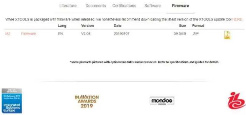
RGBLink provide firmware package for M2 device update on our website. Please use the following link to Downloads category of M2 on our website. https://www.rgblink.com/product-detail?id=713
- Enter the web page and scroll down, Downloads will be seen
Downloads
-
Download the latest released M2 Firmware.ZIP
-
Unzip the the Firmware package, here are the exact files in the package.
| Firmware Package | 2019/1/14 16:55 |
| PGM Board SD Card | 2019/3/7 9:40 |
| Upgrade Tool | 2019/1/14 16:56 |
| M2 Release Notes_V2.04_20190108 | 2019/1/14 15:20 |
| M2 Upgrade Guide_Rev.1_20180118[... | 2018/1/25 19:19 |
- Please read the M2 Upgrade Guide and follow the guide to upgrade M2 firmware or PGM Board SD Card.
In the Firmware Package there is
| Update by USB Disk | 2019/1/14 16:55 |
| Update by XTOOL | 2019/1/14 16:55 |
M2_Package_V2.04_20181224.pkg in the Update by USB Disk. M2_Package_V2.04_20181224.bin in the Update by XTOOL
In Upgrade tool there are latest released XTOOL_EN_V1.0.0.32_20180921 for Window and Mac separately

Mac

Windows
2019/1/14 16:56
2019/1/14 16:56
For easier upgrade of M2 we suggest USB upgrade as the Upgrade Guide. We also suggest you install XTOOL for other use.
6.3 Custom OSD, MASK, LOGO, STILL by XTOOL
XTOOL is not only used to upgrade M2 and other RGBLink products, it is also used to make files of OSD, Effect Change, Logo and STILL for M2. The files can be saved to the USB disk, and be loaded after custom the OSD, MASK, LOGO and STILL.
6.3.1 Installation of XTOOL
Please skip this step if there is XTOOL already installed on your computer.
Download XTOOL installation package from our website https://www.rgblink.com/software
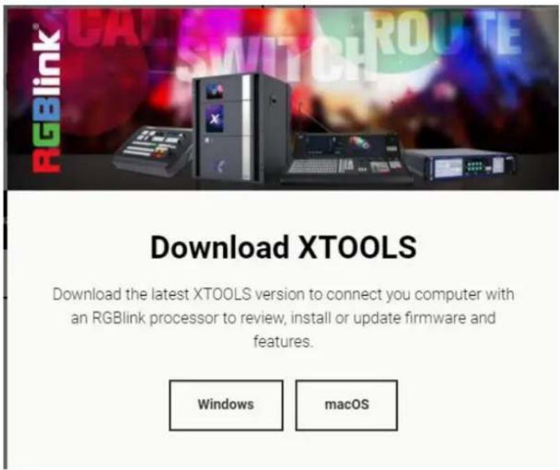
According to computer running system and download the corresponding XTOOL package.

Unzip the package and double click the set up.exe
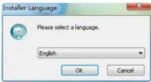
It will pop-up the installer language box, select the language, for example, select "English", and click "OK" to confirm.
Click "Next" to install:
Select "Browse..." to select the XTOOL software install location:
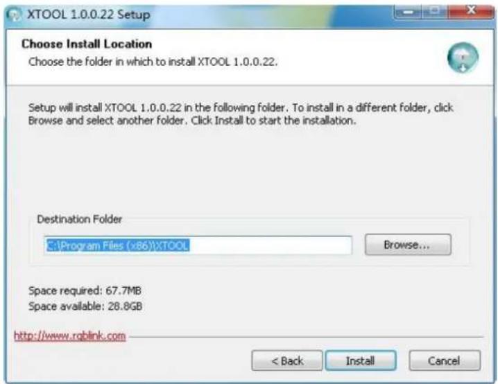
Note:
User should get the rights in "Roles Management" when install the software to disk C for Windows 7 or Windows 10. (Install as Administrator)
If user installs the XTOOL software on Windows 10, the installation should be operated under
English directory.
Click "Install":
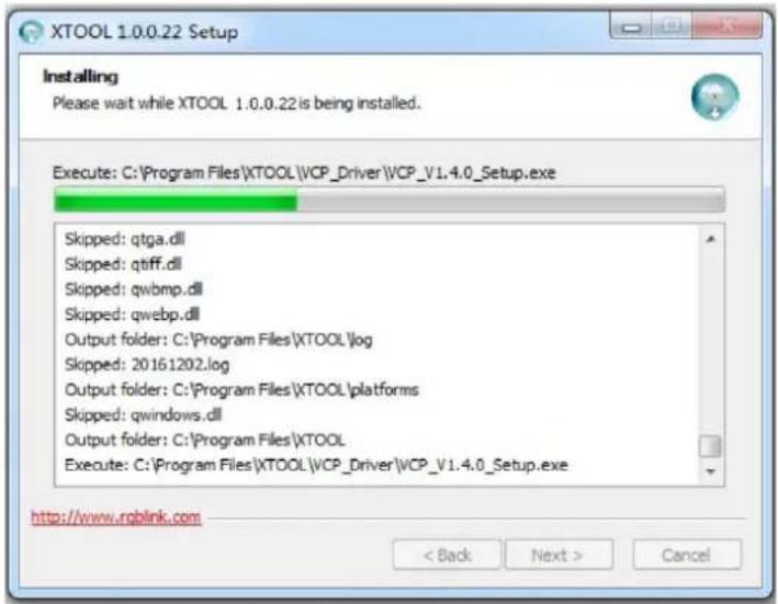
During installation, it will pop up the window of InstallShield Wizard for Virtual Com port:
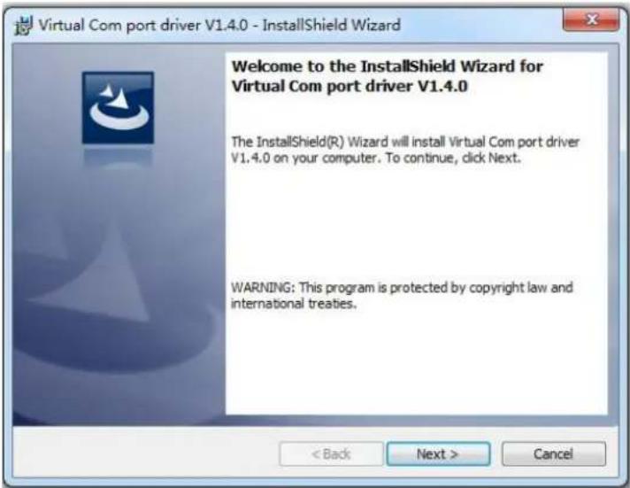
If user installs the XTOOL software for the first time, click "Next":
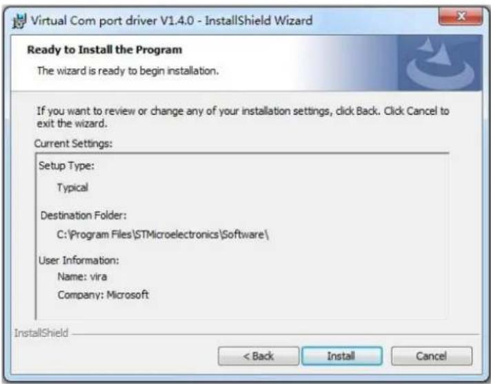
Then click "Install", as shown in the figure below:
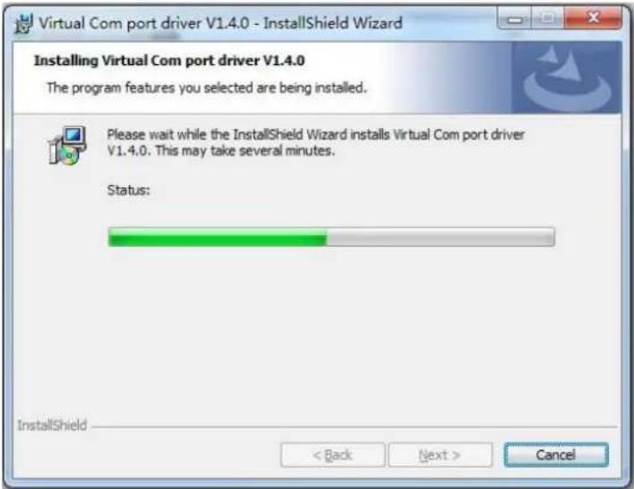
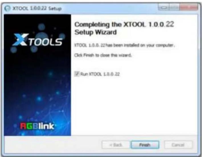
Click "Finish" and complete the installation, as shown in the figure below:
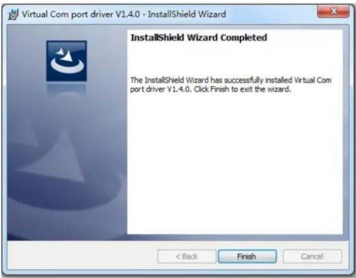
Then it will pop up the window of installation wizard for device driver, click "Next" to complete the installation.
If user have installed the XTOOL software before, click "Cancel", and it will pop up the window as below:
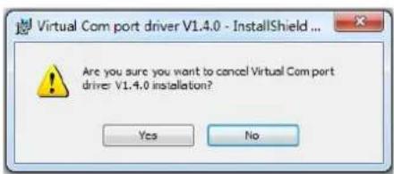
Click "Yes" to cancel installation.
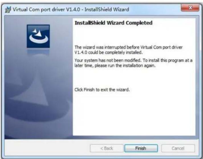
Click "Finish" to exit installation.
Then it will pop up the window of installation wizard for device driver, click "Cancel" to exit the installation.
Click "Finish" and is ready to run the XTOOL software:
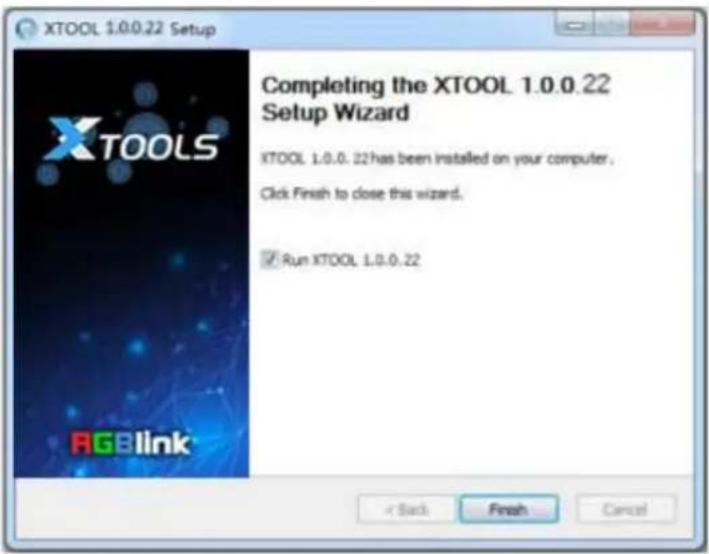
6.3.2 Custom OSD
Double click the icon to enter to the XTOOL interface, select "Toolbox", and enter to the window as follows:
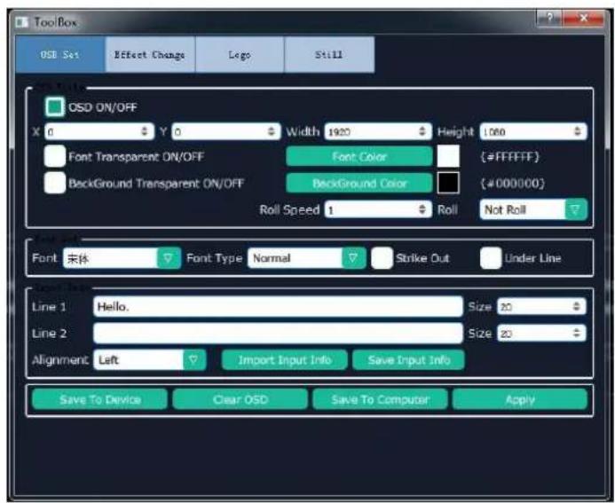
Follow the steps below:
- Tick OSD ON/OFF.
- Set the parameters as needed.
Note:
- Up to two lines of OSD can be displayed on a page at a time.
- The font settings can be saved in the PC, and can be reused without another editing.
After editing, load the OSD into the device. There are two ways to load.
(1) Load OSD directly with LAN cables.
- Change the COM No. of XTOOL according to the COM No. of the PC ([Management]). If an exclamation mark appears in the COM, restart the PC.
- Click [Save To Device].
(2) Load OSD with USB
- Click [Save to Computer] and save in order (0\~199).
- Save the file as M2\OSD.
There are rules to follow for saving the file:
- The file No. should be 0\~199 in order Interruption is not permitted.
- Save the file as M2\OSD.
● The format of USB should be FAT 32. - Press [OSD] button in the Functions area.
- Select ON and "Load From U DISK".
6.3.3 Custom Effect
Select "Effect Change" in "Toolbox", it will enter to the window as follows:
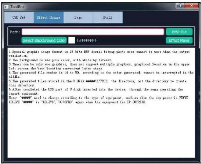
First of all, user should create a graphic image with Microsoft Paint. There are some rules to follow in creating an image:
● The background of the image should be white by default.
- It should be 24 bit BMP and the size cannot be larger than the output resolution.
- Paint one image on the canvas at a time, and it's better to be on the top left corner.
Click TOOLBOX and select Effect Change. There are also rules to follow in saving a file:
● The file number should be 14-50 in order. Interruption is not permitted.
● The file should be named as M2\EFFECT.
- USB format: FAT 32
- Insert the USB into the port in the COMM area at the rear panel.
- Press [MENU] button, and select [MASK] under [ADVANCE] menu.
- Select "Load From U DISK".
- Select "Yes".
- User can set the dimension and position of the mask.
Note:
Either EFFECT or DSK can be edited for each scene. They cannot appear at the same time.
6.3.4 Custom Logo
Select "Logo" in "Toolbox", it will enter to the window as follows:
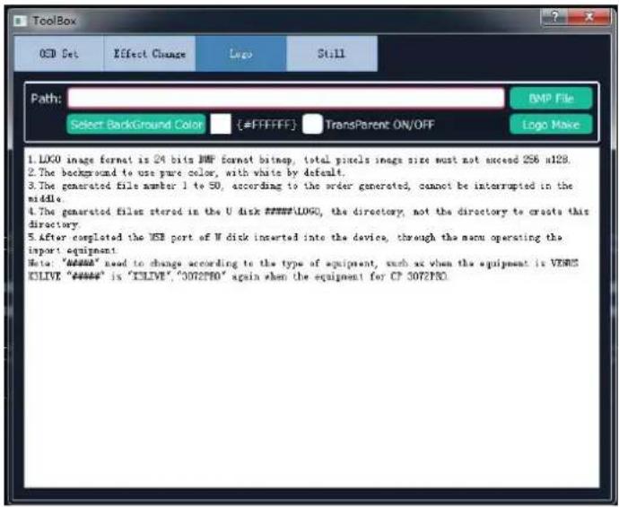
First of all, user should create a graphic image with Microsoft Paint. There are some rules to follow in creating an image:
● The background of the image should be white by default.
- It should be 24 bit BMP and the dimension should be not more than 256 × 128 .
Select the BMP file and upload. Click TOOLBOX and select LOGO.
There are rules to follow when saving the file:
- The file number should be 0\~50 in order. Interruption is not permitted.
- The file should be named as M2\LOGO.
● The format of USB should be FAT 32.
- Press [LOGO] button in the Functions area.
- Select "Load From U DISK".
- User can set the position and dimension of the LOGO.
6.3.5 Custom Still
Select "Still" in "Toolbox", it will enter to the window as follows:
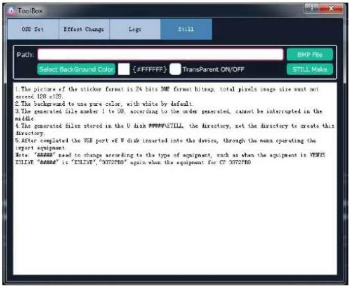
First of all, user should create a graphic image with Microsoft Paint. There are some rules to follow in creating an image:
● The background of the image should be white by default.
- It should be 24 bit BMP and the size cannot be larger than 128 × 128 .
Click TOOLBOX and select STILL. There are also rules to follow in saving a file:
● The file number should be 1-50 in order. Interruption is not permitted.
● The file should be named as M2\STILL.
- USB format: FAT 32
- Insert the USB into the port in the COMM area at the rear panel.
- Press [STILL] button in the Functions area.
- Select "Load From U DISK".
- Select "ON".
- User can set the dimension and position.
6.4 Terms & Definitions
The following terms and definitions are used throughout this guide.
- "ASCII": American Standard for Information Interchange. The standard code consisting of 7-bit coded characters (8 bits including parity check) used to exchange information between data processing systems, data communication systems, and associated equipment. The ASCII set contains control characters and graphic characters.
- “Aspect ratio”: The relationship of the horizontal dimension to the vertical dimension of an image. In viewing screens, standard TV is 4:3, or 1.33:1; HDTV is 16:9, or 1.78:1. Sometimes the “:1” is implicit, making TV = 1.33 and HDTV = 1.78.
● "AV": Audio visual, or audio video. - A “Background” is an unscaled source, typically originating from a computer. A background source appears at the system’s lowest priority — visually in back of all other sources. The abbreviation is “BK” in user manual.
- "Baudrate": Named of J.M.E. Baudot, the inventor of the Baudot telegraph code. The number of the electrical oscillations per second, called baud rate. Related to, but not the same as, transfer rate in bits per second (bps).
- "Blackburst": The video waveform without the video elements. It includes the vertical sync, horizontal sync, and the chroma burst information. Blackburst is used to synchronize video equipment to align the video output. One signal is normally used to set up an entire video system or facility. Sometimes it is called House sync.
- "BNC": Bayonet Neill-Concelman. A cable connector used extensively in television and named for its inventors. A cylindrical bayonet connector that operates with a twist-locking motion. To make the connection, align the two curved grooves in the collar of the male connector with the two projections on the outside of the female collar, Press, and twist. This allows the connector to lock into place without tools.
- "Brightness": Usually refers to the amount or intensity of video light produced on a screen without regard to color. Sometimes called "black level.
- "CAT 5": Category 5. Describes the network cabling standard that consists of four unshielded twisted pairs of copper wire terminated by RJ-45 connectors. CAT 5 cabling supports data rates up to 100 Mbps. CAT 5 is based on the EIA/TIA 568 Commercial Building Telecommunications Wiring Standard.
- "Color bars": A standard test pattern of several basic colors (white, yellow, cyan, green, magenta, red, blue, and black) as a reference for system alignment and testing. In NTSC video, the most commonly used color bars are the SMPTE standard color bars. In PAL video, the most commonly used color bars are eight full field bars. In the computer, the most commonly used color bars are two rows of reversed color bars.
- "Color burst": In color TV systems, a burst of subcarrier frequency located on the back porch of the composite video signal. This serves as a color synchronizing signal to establish a frequency and phase reference for the chroma signal. Color burst is 3.58 MHz for NTSC and 4.43 MHz for PAL.
- "Color temperature": The color quality, expressed in degrees Kelvin(K), of a light source. The higher the color temperature, the bluer the light. The lower the temperature, the
redder the light. Benchmark color temperature for the A/V industry include 5000°K, 6500°K, and 9000°K.
- “Contrast ratio”: The radio of the high light output level divided by the low light output level. In theory, the contrast radio of the television system should be at least 100:1, if not 300:1. In reality, there are several limitations. In the CRT, light from adjacent elements contaminate the area of each element. Room ambient light will contaminate the light emitted from the CRT. Well-controlled viewing conditions should yield a practical contrast ratio of 30:1 to 50:1.
- "DVI": Digital Visual Interface. The digital video connectivity standard that was developed by DDWG (Digital Display Work Group). This connection standard offers two different connectors: one with 24 pins that handles digital video signals only, and one with 29 pins that handles both digital and analog video.
- "EDID": Extended Display Identification Data – EDID is a data structure used to communicate video display information, including native resolution and vertical interval refresh rate requirements, to a source device. The source device will then output the optimal video format for the display based on the provided EDID data, ensuring proper video image quality. This communication takes place over the DDC – Display Data Channel.
- “Ethernet”: A Local Area Network (LAN) standard officially known as IEEE 802.3. Ethernet and other LAN technologies are used for interconnecting computers, printers, workstations, terminals, servers, etc. within the same building or campus. Ethernet operates over twisted pair and over coaxial cable at speeds starting at 10Mbps. For LAN interconnectivity, Ethernet is physical link and data link protocol reflecting the two lowest layers of the OSI Reference Model.
- "Frame": In interlaced video, a frame is one complete picture. A video frame is made up of two fields, or two sets of interlaced lines. In a film, a frame is one still picture of a series that makes up a motion picture.
- “Gamma”: The light output of a CRT is not linear with respect to the voltage input. The difference between what you should have and what is actually output is known as gamma.
- "HDMI" - High – Definition Multimedia Interface: An interface used primarily in consumer electronics for the transmission of uncompressed high definition video, up to 8 channels of audio, and control signals, over a single cable. HDMI is the de facto standard for HDTV displays, Blu-ray Disc players, and other HDTV electronics. Introduced in 2003, the HDMI specification has gone through several revisions.
- "HDSDI": The high-definition version of SDI specified in SMPTE-292M. This signal standard transmits audio and video with 10 bit depth and 4:2:2 color quantization over a single coaxial cable with a data rate of 1.485 Gbit/second. Multiple video resolutions exists including progressive 1280x720 and interlaced 1920x1080 resolution. Up to 32 audio signals are carried in the ancillary data.
- “JPEG” (Joint photographic Expects Group): Commonly used method of lossy compression for photographic images using a discreet cosine transfer function. The degree of compression can be adjusted, allowing a selectable tradeoff between storage size and image quality. JPEG typically achieves 10:1 compression with little perceptible loss in image quality. Produces blocking artifacts.
● "MPEG": Motion Picture Expect Group. A standard committee under the auspices of the
International Standards Organization working on algorithm standards that allow digital compression, storage and transmission of moving image information such as motion video, CD-quality audio, and control data at CD-ROM bandwidth. The MPEG algorithm provides inter-frame compression of video images and can have an effective compression rate of 100:1 to 200:1.
- "NTSC": The color video standard used in North America and some other parts of the world created by the National Television Standards Committee in the 1950s. A color signal must be compatible with black-and-white TV sets. NTSC utilizes an interlaced video signals, 525 lines of resolution with a refresh rate of 60 fields per second (60 Hz). Each frame is comprised of two fields of 262.5 lines each, running at an effective rate of 30 frames per second.
- "Operator": Refers to the person who uses the system.
- "PAL": Phase Alternate Line. A television standard in which the phase of the color carrier is alternated from line to line. It takes four full pictures (8 fields) for the color-to-horizontal phase relationship to return to the reference point. This alternation helps cancel out phase errors. For this reason, the hue control is not needed on a PAL TV set. PAL, in many transmission forms, is widely used in Western Europe, Australia, Africa, the Middle East, and Micronesia. PAL uses 625-line, 50-filed (25 fps) composite color transmission system.
- "PIP": Picture-in-Picture. A small picture within a larger picture created by scaling down one of the images to make it smaller. Each picture requires a separate video source such as a camera, VCR, or computer. Other forms of PIP displays include Picture-by-Picture (PBP) and Picture-with-Picture (PWP), which are commonly used with 16:9 aspect display devices. PBP and PWP image formats require a separate scaler for each video window.
- "Polarity": The positive and negative orientation of a signal. Polarity usually refers to the direction or a level with respect to a reference (e.g. positive sync polarity means that sync occurs when the signal is going in the positive direction).
- "RJ-45": Registered Jack-45. A connector similar to a telephone connector that holds up to eight wires, used for connecting Ethernet devices.
- "RS-232": An Electronic Industries Association (EIA) serial digital interface standard specifying the characteristics of the communication path between two devices using either DB-9 or DB-25 connectors. This standard is used for relatively short-range communication and does not specify balanced control lines. RS-232 is a serial control standard with a set number of conductors, data rate, word length, and type of connector to be used. The standard specifies component connection standards with regard to the computer interface. It is also called RS-232-C, which is the third version of the RS-232 standard, and is functionally identical to the CCITT V.24 standard.
- "Saturation": Chroma, chroma gain. The intensity of the color, or the extent to which a given color in any image is free from white. The less white in a color, the truer the color or the greater its saturation. On a display device, the color control adjusts the saturation. Not to be confused with the brightness, saturation is the amount of pigment in a color, and not the intensity. Low saturation is like adding white to the color. For example, a low-saturated red looks pink.
- "Scaling": A conversion of a video or computer graphic signal from a starting resolution to a new resolution. Scaling from one resolution to another is typically done to optimize the
signal for input to an image processor, transmission path or to improve its quality when presented on a particular display.
- "SDI": Serial Digital Interface. The standard based on a 270 Mbps transfer rate. This is a 10-bit, scrambled, polarity independent interface with common scrambling for both component ITU-R 601 and composite digital video and four channels of (embedded) digital audio.
- "Seamless Switching": A feature found on many video switchers. This feature causes the switcher to wait until the vertical interval to switch. This avoid a glitch (temporary scrambling) which normally is seen when switching between sources.
- "SMPTE": Society of Motion Picture and Television Engineers. A global organization, based in the United States, that sets standards for baseband visual communications. This includes film as well as video and television standards.
- "S-Video": A composite video signal separated into the luma ("Y" is for luma, or black and white information; brightness) and the chroma ("C" is an abbreviation for chroma, or color information).
- “Sync”: Synchronization. In video, sync is a means of controlling the timing of an event with respect to other events. This is accomplished with timing pulses to insure that each step in a process occurs at the correct time. For example, horizontal sync determines exactly when to begin each horizontal scan line. Vertical sync determines when the image is to be refreshed to start a new field or frame. There are many other types of sync in video system.(Also known as “sync signal” or “sync pulse.”)
- "TCP/IP": Transmission Control Protocol/Internet Protocol. The communication protocol of the Internet. Computers and devices with direct access to the Internet are provided with a copy of the TCP/IP program to allow them to send and receive information in an understandable form.
- "USB": Universal Serial Bus. USB was developed by seven PC and telecom industry leaders (Compaq, DEC, IBM, Intel, Microsoft, NEC, and Northern Telecom). The goal was easy plug-and-play expansion outside the box, requiring no additional circuit cards. Up to 127 external computer devices may be added through a USB hub, which may be conveniently located in a keyboard or monitor. USB devices can be attached or detached without removing computer power. The number of devices being designed for USB continues to grow, from keyboards, mice, and printers to scanners, digital cameras, and ZIP drives.
- "VESA": Video Electronics Standards Association. A nonprofit number organization dedicated to facilitating and promoting personal computer graphics through improved standards for the benefit of the end-user. www.vesa.org
- "VGA": Video Graphics Array. Introduced by IBM in 1987, VGA is an analog signal with TTL level separate horizontal and vertical sync. The video outputs to a 15-pin HD connector and has a horizontal scan frequency of 31.5kHz and vertical frequency of 70Hz (Mode 1, 2) and 60Hz (Mode 3). The signal is non-interlaced in modes 1, 2, and 3 and interlaced when using the 8514/A card ( 35.5kHz, 86Hz ) in mode 4. It has a pixel by line resolution of 640× 480 with a color palette of 16 bits and 256,000 colors.
- "YCrCb": Used to describe the color space for interlaced component video.
- "YPbPr": Used to describe the color space for progressive-scan (non-interlaced) component video.
6.5 Revision History
The table below lists the changes to the Video Processor User Manual.
| Format | Time | ECO# | Description | Principal |
| V1.0 | 20180201 | 0000# | Release | Linger |
| V1.1 | 20190118 | 0001 | Revise “In the Box” | Fanny |
| V1.2 | 20190306 | 0002 | Add “3.5.5 Presentation”Revise “6.2 Upgrade”Revise “6.3 Use XTOOL” | Fanny |
| V1.3 | 20190506 | 0003 | Add Tally Pin Definition to SpecificaAdd Adjust R,G,B of SDI,VGA,CVBSUSB Input | Fanny |
- RGBlink
- CONTENTS
- Declarations
- FCC/Warranty
- Federal Communications Commission (FCC) Statement
- Guarantee and Compensation
- Operators Safety Summary
- Do Not Remove Covers or Panels
- Power Source
- Grounding the Product
- Use the Proper Power Cord
- Use the Proper Fuse
- Do Not Operate in Explosive Atmospheres
- Installation Safety Summary
- Safety Precautions
- Unpacking and Inspection
- Site Preparation
- In the Box
- Note:
- Product Overview
- Rear Panel
- Input Option Slots
- Front Panel
- Layer Adjustment Buttons
- Layer Selection Buttons
- Layer Effect Buttons
- Multiview Presets Buttons
- Stored Presets Buttons
- Independent Effects Switching Buttons
- OSD Edit Buttons
- Switchers
- Dimension
- Chapter 2 Installing Your Product
- Plugging in Signals
- Plugging in Main Power
- Turning on Your Product
- Chapter 3 Using Your Product
- Using the MENU Button
- Understanding the MENU Structure
- Using the Menu
- Understanding the Display
- Understanding the Main Menu
- Input Menu
- Output Menu
- Background Menu
- Advance Menu
- Language Menu
- System Menu
- Factory Reset Menu
- PST Mode
- Signal Selection
- Add or Delete Layer
- Freeze the Layer
- Freeze a PST layer
- Freeze a PGM layer
- Multiview Presets
- Set the Position
- Scale and Crop the Layer
- DSK Settings
- Instructions
- Key In
- Key Out
- User
- BLEND Settings
- Mask Settings
- Enable the mask function:
- Select mask:
- Mask settings:
- Custom buttons:
- Set a Mask:
- Transition Settings
- Adjust R,G,B of SDI,VGA,CVBS,USB Input
- System Mode
- Normal
- 4K1K
- Normal Mode
- Overlayer
- 4K2K
- Matrix
- Presentation
- Switching Layers
- Background Picture
- Input Source
- Captured Picture
- Picture file loaded with U Disk
- Before loading a picture:
- When the resolution meets the criteria
- When the resolution does NOT meet the criteria
- Importing the pictures
- By U Disk
- By TF card
- Set as background
- Set the Output Resolution
- Select the Output Resolution
- Custom the Output Resolution
- Using Black Out
- Saving Views
- Recall Saved Settings
- Product
- Options
- Input Options
- Accessories
- Specification
- TALLY Pin Definition
- Upgrade
- Custom OSD, MASK, LOGO, STILL by XTOOL
- Installation of XTOOL
- Custom OSD
- Custom Effect
- Custom Logo
- Custom Still
- Terms & Definitions
- Revision History
Brand : RGBlink
Model : M2
Category : Controller