1503H - Monitor GeChic - Free user manual and instructions
Find the device manual for free 1503H GeChic in PDF.


User questions about 1503H GeChic
0 question about this device. Answer the ones you know or ask your own.
Ask a new question about this device
Download the instructions for your Monitor in PDF format for free! Find your manual 1503H - GeChic and take your electronic device back in hand. On this page are published all the documents necessary for the use of your device. 1503H by GeChic.
USER MANUAL 1503H GeChic
Section 1 On-Lap Monitor and Accessories —1
Section 2 Notices of On-Lap Monitor —3
Section 3 Safety Precautions —3
Section 4 Safety Instructions & Product Maintenance —4
Section 5 LCD Pixel Statement —4
Section 6 Disposal of Electronic Equipment —4
Chapter 2 Installation Instructions —5
Section 1 Protective Cover & Detachable Stand —5
Section 2 Connect the Video Cable and USB Touch and Power Cable —6
Section 3 Install Rear Dock —7
Section 4 Install On-Lap Proprietary HDMI-A & USB-A to Dock Port Cable —8
Section 5 1503 Multi-Mount Kit Installation —9
Section 6 Stand 4 Installation —10
Chapter 3 Power On and Off the On-Lap Monitor —10
Section 1 Power On and Off the On-Lap Monitor —10
Section 2 Monitor Display Setting —10
Section 3 Windows 10/8.1/7 Touchscreen Setting —11
Section 4 Windows 10/8.1 Touch Gesture Description —12
Chapter 4 Hot Keys and OSD Instructions —13
Section 1 Hot Keys & LED lights Description —13
Section 2 OSD Description —13
Section 3 Low Power Protection Warning —16
Chapter 5 Specification —16
Section 1 Plug and Play —16
Section 2 Pin Assignment —16
Section 3 Specification —17
Section 4 Troubleshooting —18
目次
第一章 内容物の解説 ——20
Chapter 1 Content Description
Section 1 On-Lap Monitor and Accessories
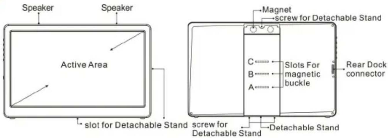
- Parts Description
text_image
Speaker Speaker Active Area Magnet screw for Detachable Stand C——— Slots For magnetic buckle B——— A——— Rear Dock connector slot for Detachable Stand screw for Detachable Stand Detachable StandFig.: On-Lap 1503 front and back

text_image
Power On/Off Power On/Off Indicator Exit/Auto Menu/Select Volume Up/Up Volume Down/DownFig.: 1503 buttons and LED light description
text_image
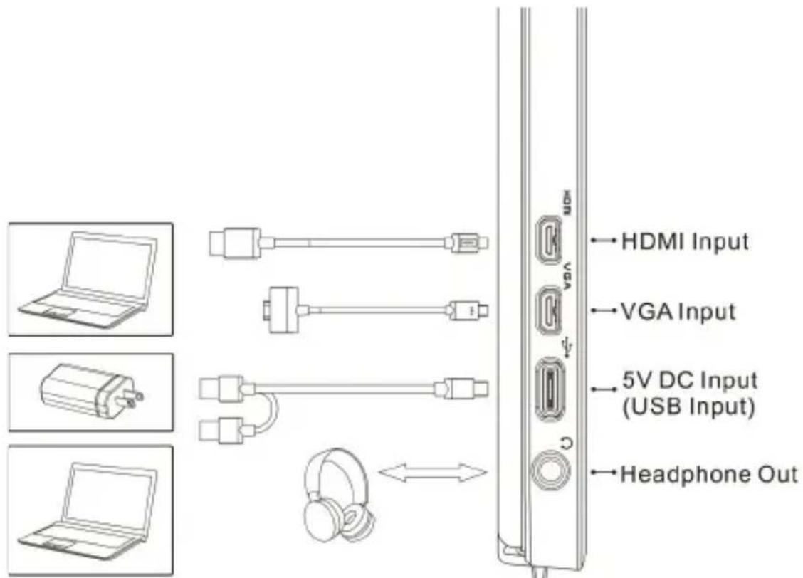
HDMI Input VGA Input 5V DC Input (USB Input) Headphone OutFig.: On-Lap 1503 input & output ports
- Package & Accessories
| Accessories 1503I 1503H 1503A | |||
| USB-A to USB-C Power Cable(1.2m) *1 No Yes Yes | |||
| USB-A to USB-C Power & Touch Signal Cable(1.2m) *1 Yes No | No | ||
| USB-A (male) to USB-A (female) Power Cable(1.2m) *1 Yes No | No | ||
| HDMI-A to micro-HDMI Video Cable(1.2m) *1 Yes Yes Yes | |||
| Charger(5V, Max. 2A) *1 Yes Yes No | |||
| Protective Cover & Detachable Stand*1 Yes Yes Yes | |||
| Manual *1 Yes Yes Yes | |||
| Slotted Screw-silver (M2 x 7.5mm) *1 | Yes Yes Yes | ||
| Phillips Screw-black (M2 x 3.2mm) *2 | Yes Yes Yes | ||
- Optional Accessories
| Item | Description |
| On-Lap Proprietary VGA Cable (1.2m) | Proprietary cable for On-Lap products.One plug is D-sub (male) for connecting to computer's VGA port; the other plug is micro-HDMI (male) for con- |
| HDMI-A to micro-HDMI Video Cable (2.1m) | One plug is HDMI-A (male) for connecting to computer's HDMI-A port; the other plug is micro-HDMI (male) for connecting to On-Lap1503. |
| Mini-HDMI to micro- HDMI Video Cable (2.1m) | One plug is mini-HDMI (male) for camera's mini-HDMI port; the other plug is micro-HDM (male) connecting to On-Lap1503. |
| USB-A to USB-C Power &Touch Signal Cable (2.1m) | One plug is USB-A (male) for adapter / computer USB port; the other one is USB-C (male) for 1503 connecting to On-Lap1503. |
| On-Lap Proprietary HDMI-A & USB-A to Dock Port Cable (1.2m) | Proprietary cable for On-Lap 1503.One plug is 1503 proprietary connector for plugging into Rear Dock's port; the other two plugs are HDMI-A (male) and USB-A (male). Please refer to Chapter 2>Section 4. |
| Rear Dock | The Rear Dock shall be installed on the backside connect-or of 1503. It equips with HDMI-A input and USB-A input for installing Computer Stick or HDMI wireless display. For attaching a power bank on the Rear Dock, refer to Chap-ter 2>Section 3. |
| Multi-Mount Kit for 1503 | Proprietary for On-Lap 1503. With 4 VESA 100 screw holes and a 1/4" screw holes for screwing On-Lap 1503 on VESA 100 Arm or camera cradle head. Refer to Chapter 2 > Section 5. |
| Stand 4 | An optional stand for On Lap 1503. It supports horizontal display and 4 adjustable viewing angles. Refer to Charpt-er2> Section6. |
Section 2 Notice of On-Lap Monitor
- When plugging in/out the cables, do make sure the application of force is in horizontal direction—do not shake the port or plug in vertical direction. Any damage caused by wrong plug urging is not included in warranty coverage.
- The power input specification for On-Lap monitor is 5V 2A DC current. Input power over than 5V will cause breakdowns on monitor and this damage is not included in warranty coverage. It is suggested to connect both plugs of USB power cable to computer's USB ports or manufacturer's 5V-2A adapter.
- Unstable power input will interfere with touch signal, resulting inaccurate or failed touch function. If some high power consumption equipment share the power in the same electricity network, it may cause acute electricity fluctuation. It is suggested to use the USB port on laptop or manufacturer's 5V-2A charger.
- Do not put touch monitor near to light blub, electric cord, or anything with great electromagnetic wave which may disturb projective capacitive touch monitor and cause touchscreen function abnormal.
- Please do not use sharp objects o touch the screen. Gently use the finger to touch or swipe on the screen. While touching the screen, please keep finger clean and dry. Do not press the screen forcefully.
- Notice for Monitor Clean Disconnect power input before cleaning. Please use soft cloth to clean touch screen monitor. If something is hard to wipe off, please wet the cloth and wipe again. Please do not use chlorine, alcohol, ammonia, detergent or other corroding solvents. These solvents may cause damage to the touch screen monitor or leave unremovable residue.
- Notice for Monitor Operation Avoid to expose the monitor directly under sunlight for long, which may result in damage. When monitor displays different images, image brightness may become slightly uneven.
Section 3 Safety Precautions
- The Product may be severely damaged from overturning or falling. Please do not place on a shaky or unstable table, cupboard or trolley. Do not use the On-Lap Monitor on a moving vehicle.
- Do not place the items on a vibrating surface, vibration may cause damage to the internal components.
- The product is not waterproof. Do not use the Product at or near a place with water.
- Do not insert any object into the Product's slots or gaps.
- Loudness warning! Avoid volume levels that may be harmful to your hearing. Please check the volume setting before you use the Audio Jack.
-
Please notice the plug in the box is applicable to its AC adapter only.
-
Monitor may be broken when heavy pressure or sharp object is applied to it. Please put it into Protection Stand with glass side inward and avoid pressing the monitor violently. Avoid rubbing the glass surface or any action might produce static electricity which may cause malfunction on the display.
- Overuse shall hurt eyesight. Rest for 10 minutes after watching monitor for 30 minutes. Do not watch monitor under age 2; children more than age 2 do not watch monitor over 1 hour per day.
Section 4 Safety Instruction & Product Maintenance
Please read this manual carefully and observe the operation instructions and precautionary notes. Do retain this document for future reference.
Gechic Corporation does not guarantee this product work uninterrupted or work without any error. Only the breakdown under normal circumstance in warranty period is included in warranty.
The situations excluded from warranty coverage are:
(1)The bar code is removed or worn down.
(2) This product is refitted, token apart, or modified.
(3) Display and touch function are normal; however, the appearance is varying (i.e., ageing, attrition, scratch, color changing and etc.)
(4) Any breakdown caused by power supply. (i.e., inputting power over 5V or unsteady current)
(5) Any damage caused by misoperation which is not directed by this manual. (i.e., Plug or unplug the cable by wrong direction to cause damage on cable or monitor.)
(6)Damage caused by hitting or cracking the monitor in accident or purposely and make it fall down or overturn.
Section 5 LCD Pixel Statement
The On-Lap monitor uses a high quality LCD panel. Nevertheless, there might be instances where defective pixels may occur; however, this will not affect the normal functioning of the product.
Section 6 Disposal of Electronic Equipment
The electronic equipment and batteries should not be disposed with household waste but should be left at an appropriate collection point for recycling.

5
Chapter 2 Installation Instruction Section 1 Protective Cover & Detachable Stand
1. Install Protective Cover
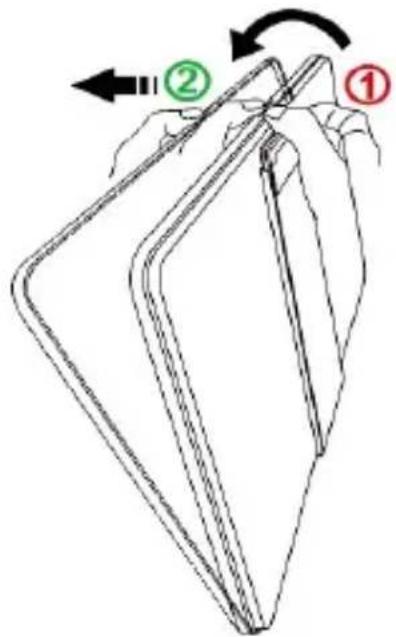
Take monitor out: Hold the monitor by one hand and pull out the cover by the other hand.
Put monitor back: Cover the monitor by Protective Cover's lower half first, then cover the monitor with Protective cover's upper half.
text_image
Diagram showing a folded paper or sheet with labeled parts ①, ② and directional arrows indicating folding or folding.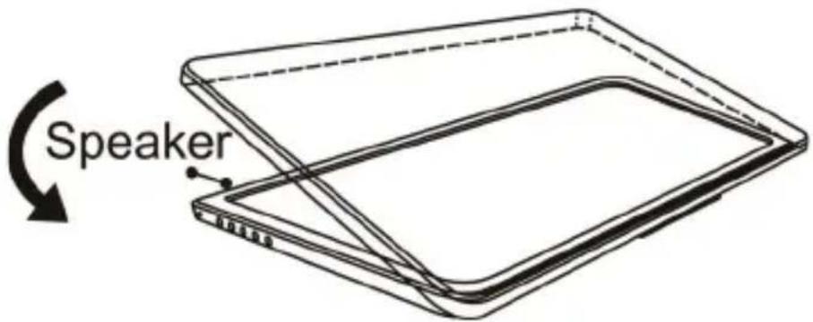
text_image
SpeakerFig.: Take the monitor out and put it into the protective cover.
Caution: In order to avoid dropping or breaking the monitor, please keep the back of monitor outward the Protective Cover when not in usage.
2. Install Detachable Stand
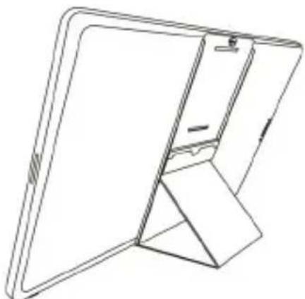
A. Horizontal Display
Refer to the Fig; take the magnetic buckle off first. There are 4 slots for aligning. Put the magnetic buckle in one of the slots and the Cover Stand is set.
natural_image
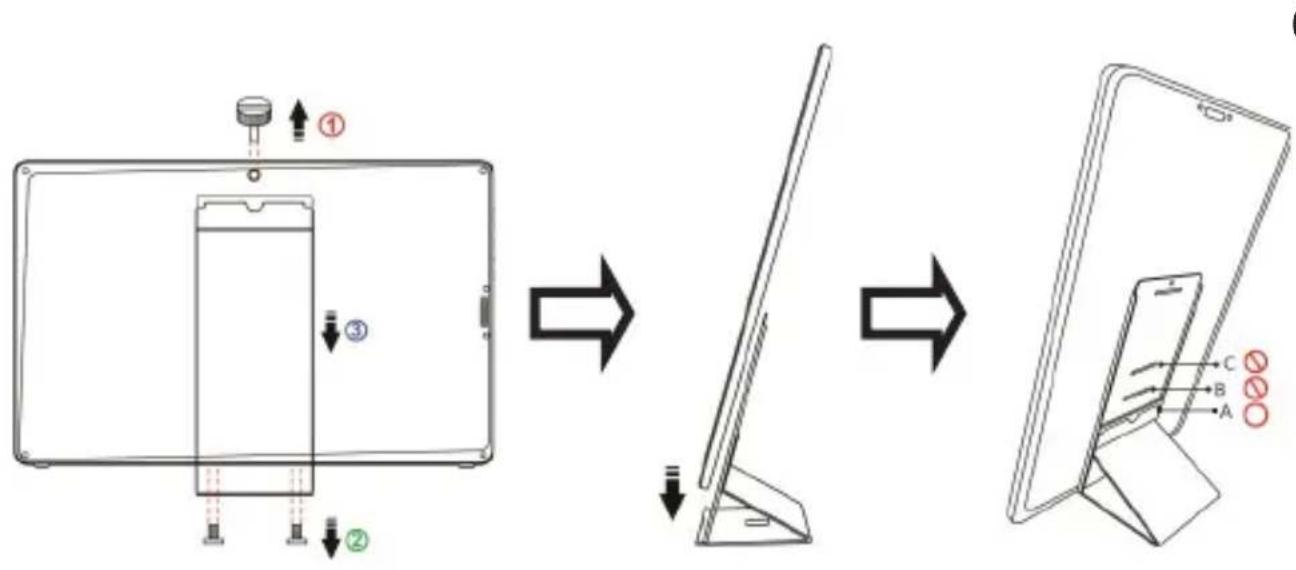
Line drawing of a folding screen or tray device (no text or symbols)B. Vertical Display
(On-Lap 1503I is not recommended for vertical display)
Refer to the Fig on next page; remove the 3 screws. Take off the Detachable Stand and put the magnetic buckle into the lower slot. Align Stand's mental latch to the slots on the side of monitor and put monitor into the stand finally.
flowchart
graph TD
    A["① Component"] --> B["② Component"]
    B --> C["③ Component"]
    C --> D["④ Component"]
    D --> E["⑤ Component"]
    style A fill:#f9f,stroke:#333
    style B fill:#ccf,stroke:#333
    style C fill:#cfc,stroke:#333
    style D fill:#fcc,stroke:#333
    style E fill:#fcf,stroke:#333
6
Caution: In order to avoid overturning, the magnetic buckle can be only put in slot A, but not B or C. While setting Monitor vertically, touching or hitting Monitor is forbidden.
Section 2 Connect the Video Cable and USB Touch and Power Cable
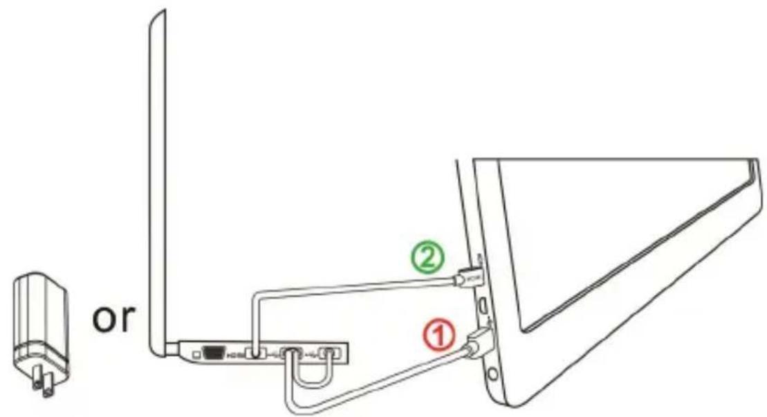
- Connect Video cable and USB power cable
Refer to the Fig below. Please connect USB power cable first and then connect video cable secondly. Power supply could be form computer's two USB ports or 5V-2A charger.
PS. If single USB port of the laptop can't provide sufficient power, it may cause monitor flash or fail to display; please plug both USB touch cable and power cable into laptop's USB ports for providing twice power.
text_image
or ① ②7
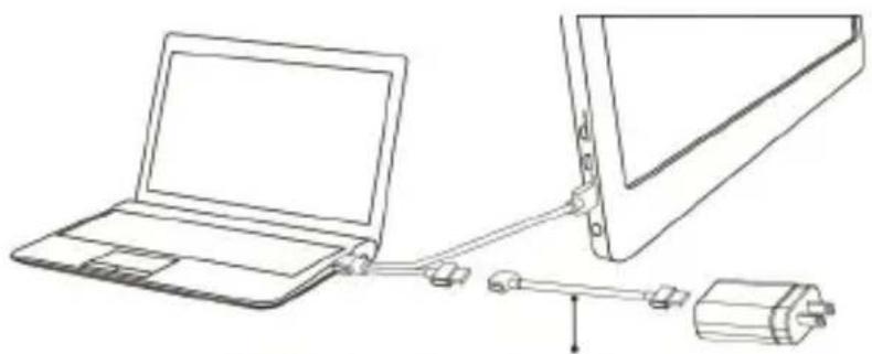
- Connect USB-A(male) to USB-A(femalel) Power Cable (1.2m) and 5V-2A Charger (Applied to On-Lap 1503I)
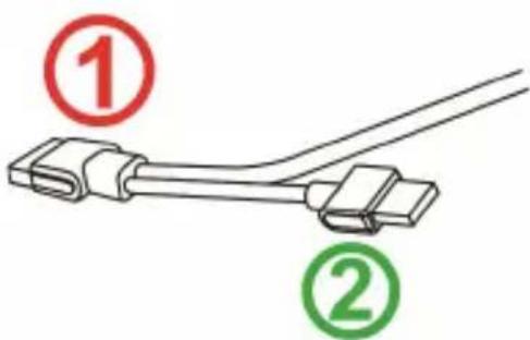
When the laptop equipped with only one USB port can't supply enough power, please connect the ② male plug(10cm long) to USB-A(male)—USB-A(female) cable (1.2 meters). By this, 5V-2A adapter can be connected for power supply.
natural_image
Line drawing of a laptop connected to a device via cable (no text or symbols)USB-A(male) to USB(female) power cable
Notice: Refer to right Fig., USB-A(female) touch power cable's ① plug can transmit both power and touch signal; ② plug is for power supply only. If ① plug isn't connected to computer's USB port, touch function cannot be used.
text_image
① ②Section 3 Install Rear Dock
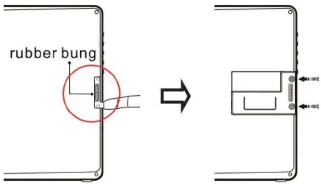
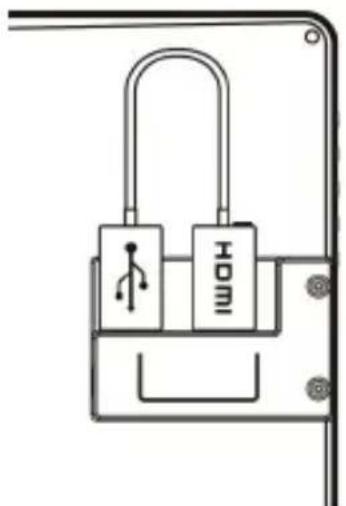
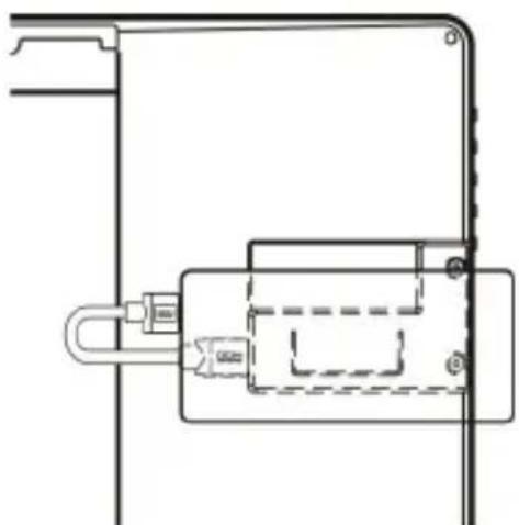
From Fig. below, take off the rubber bung on the back of monitor first. Insert "Rear Dock" into 1503's connector and then secure it by screws. Insert you Compute Stick, Stick type PC, or wireless HDMI adapter, such as Microsoft® Wireless Display Adapter into Rear Dock's HDMI-A port. (Please select "HDMI 2" as input source by OSD setting)
text_image
rubber bung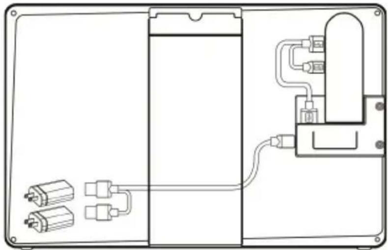
natural_image
Technical line drawing of a device enclosure with internal components and wiring (no text or symbols)Fig: Install a Compute Stick
natural_image
Simple line drawing of a padlock with two labeled buttons (no text or symbols beyond the label)Fig.: Install A Wireless HDMI Adapter
natural_image
Technical line drawing of a mechanical assembly with no visible text or symbolsFig.: Install A Power Bank
Warning : While using On Lap monitor together with stick type PC, a powerful battery with at least 4A power output capacity is recommended.
Section 4 Install On-Lap Proprietary HDMI-A & USB-A to Dock Port Cable
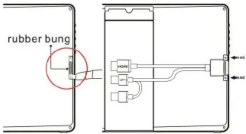
From Fig. below, take off the rubber bung on the back of monitor first. Insert On-Lap Proprietary HDMI-A & USB-A to Dock Port Cable into 1503's port on
the back and secure it by screws. Connect USB-A plug to computer's USB port and connect HDMI-A plug to computer's HDMI port. (Please select "HDMI 2" as input source by OSD setting)
Fig.: Take off the rubber bung and install the cable
text_image
rubber bungSection 5 1503 Multi-Mount Kit Installation
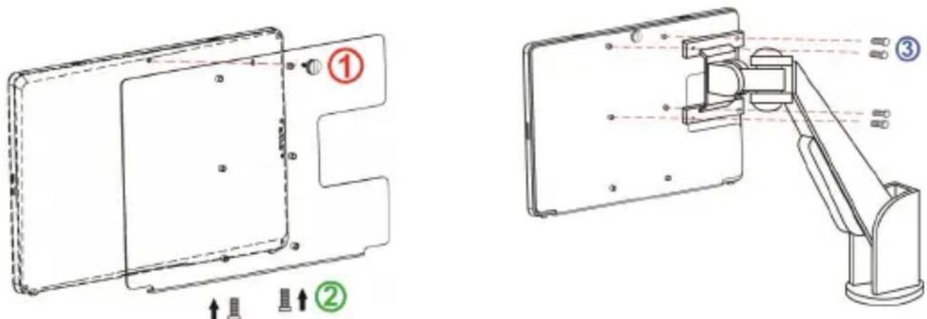
From Fig. below, screw Multi-Mount Kit to On-Lap 1503 monitor first. Align the VESA 100 screw holes of Multi-Mount Kit to VESA arm's and then secure the monitor to VESA Arm by attached 4 screws.
text_image
Technical diagram showing two views of a device with labeled components and assembly instructionsFig: ① ② Screw Multi-Mount Kit to On-Lap monitor
and ③ screw monitor with Multi-Mount Kit to VESA 100 arm.
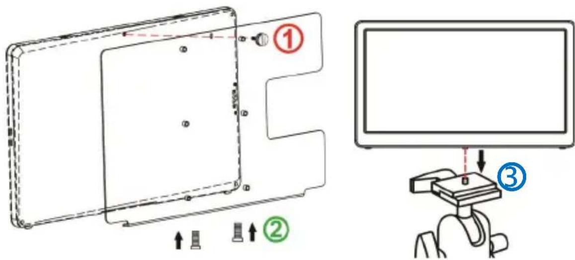
From Fig. below, screw Multi-Mount Kit to On-Lap 1503 monitor first. Align the 1/4" screw on Tripod's cradle head to the screw hole of Multi-Mount Kit and secure them by spin.
Fig: ① ② Screw Multi-Mount Kit to On-Lap monitor and ③ screw it to the camera cradle head.
text_image
Technical diagram showing assembly steps of a device with numbered annotations and directional arrowsCaution: If Multi-Mount Kit is not screwed to On-Lap monitor, monitor may fall and damage. When moving and adjusting the monitor, please hold Multi-Mount Kit. Do not drag the monitor itself directly.
Section 6 Stand 4 Installation
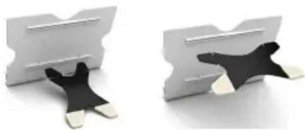
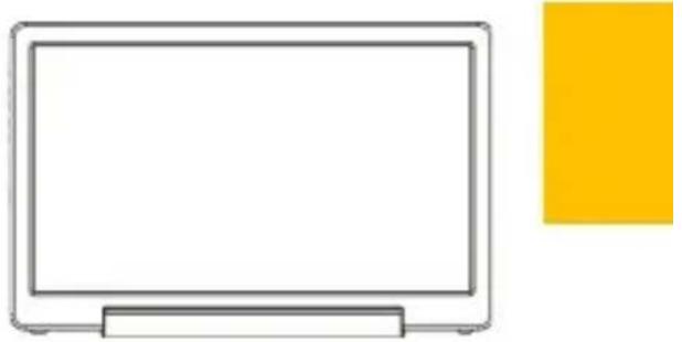
Select the desired angle placement to assemble Stand 4. During assembly, check if X plate is properly inserted onto slot and position On-Lap 1503 at the bottom center of monitor.
natural_image
Two 3D-rendered white and black paper clip holders with cutouts, no text or symbols visiblenatural_image
Simple line drawing of a flat-screen computer monitor (no text or symbols)Fig: Place the monitor in Stand 4
Chapter 3 Power On and Off the On-Lap Monitor Section 1 Power On and Off the On-Lap
From Off state to On state: Press Power Button ⏻ to activate On/Off.
Section 2 Monitor Display Setting
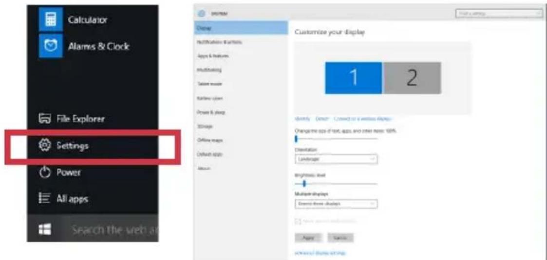
- Set Extended Display Mode-Windows 10 System
Press and choose "Settings" > select "System" > select "Display". Then choose "Extend thesedisplays" at Multiple displays.
Refer to 3.Set Extended Display Mode-Windows 7 System for resolution.
text_image
Calculator Alarms & Clock File Explorer Settings Power All apps Search the web at Change Defaulting & Settings Apps & Features Multimining Texter mode Runtime time Power & sleep Storage Offline maps Default size About Customize your display 1 2 Modify - Grow - Connect or a wireless dialog Change the size of text, apps, and other items: 100% Classification Landings Brightness level Multiple displays Create three displays Apply Cancel Show these strings- Set Extended Display Mode-Windows 8.1 System
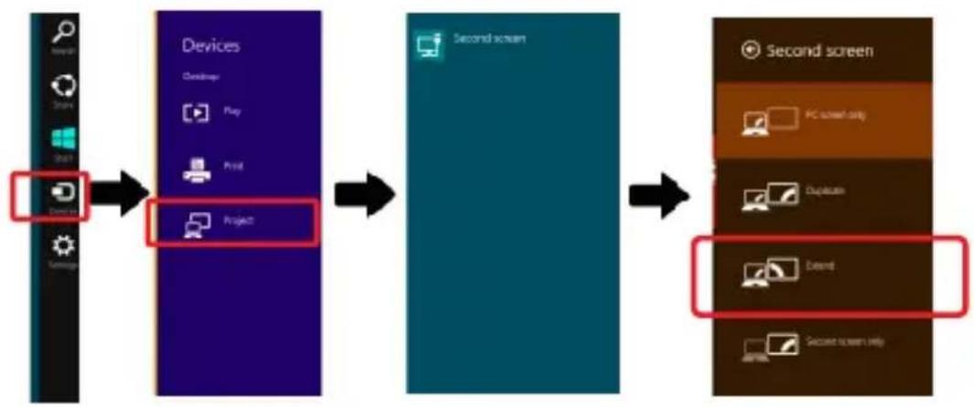
Select directly from right side of screen [Devices] ->select [Project]->select [2 ^nd Monitor] -> select [Extend Mode]
For screen resolution setting please refer to the followings.

flowchart
graph LR
    A["Start"] --> B["Devices"]
    B --> C["Project"]
    C --> D["Second screen"]
    D --> E["Extended Screen"]
3. Set Extended Display Mode-Windows 7 System
- Click on icon
- Click on Control Panel > Appearance and Personalization
- Click on Display > Connect to an external display.
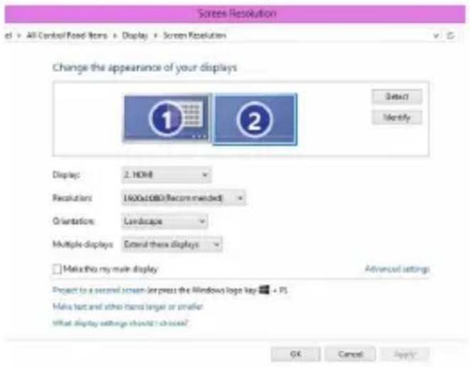
Normally Display ① is the laptop's monitor, Display ② is the external monitor. Click on Detect if you are unsure.
● At Display, select "2.HDMI" (digital video) or "2. display device:
VGA" (analog video) for Display
- Select Resoluton "1920x1080" for 1503H& 1503I. Select Resolution "1366x768" for 1503A.
- Select "Landscape" or "Portrait" for Orientation.
- Select "Extend these displays" for Multiple display, and drag Display 2 to the right side of Display 1. For Duplicated mode, select "Duplicate these displays".
- Select OK and exit after saving the settings.
text_image
Screen Resolution All Control Load Items > Display > Screen Resolution Change the appearance of your displays 1 2 Display: 2. HDMI Recalculation: 1600x1080 (Recommended) Orientation: Landscape Multiple displays: External these displays Make this my main display Project to a second screen or press the Windows logo key ▼ PS Make text and other items larger or smaller What display settings should choose? OK Cancel ApplySection 3 Windows 10/8.1/7 Touchscreen Setting
(Notice: Only 1503I supports Touch Function)
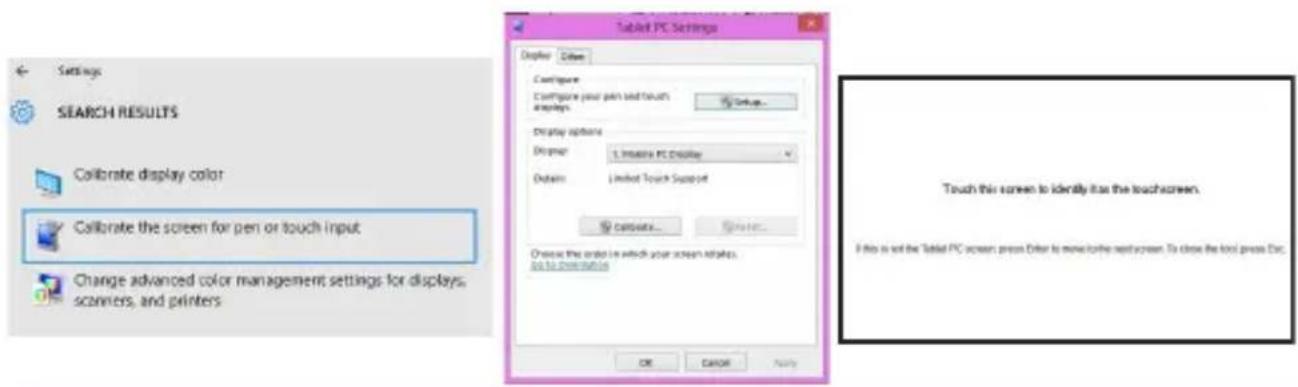
If you find the cursor acts wrongly, please calibrate the monitors in Windows system. Please connect 1503I to laptop first, if not, the calibration can't be begun.
In Windows10, search" calibration" at 'Settings',select 'Calibrate the screen for pen or touch input'. In Windows8.1/7, Select 'Tablet PC Setting' of Control Panel to calibrate touch input.
As Fig. below, please select "Setting (S)", when Windows message appears on the screen of On-Lap 1503I, follow the direction to touch the screen and the setting is complete.
text_image
Settings SEARCH RESULTS Collaborate display color Collaborate the screen for pen or touch input Change advanced color management settings for displays, scanners, and printers Tablet PC Settings Display Edit Configure Configure your pen and touch displays Display options Explorer: 1. Interactive PC Display Options: Limited Touch Support Connects... Search... Choose the order in which your screen relates. for to continue OK Cancel Apply Touch this screen to identify how the touchscreen. If this is not the Tablet PC screen press order to move to the next screen. To close the tool press Esc.Notice of operating system compliance
On-Lap 1503I supports Windows10/8.1/7 . You can plug & touch on Windows 10/8.1/7 without any driver installation
Some revisions of Windows 8/8.1 before 2015/10/15 may not recognize 1503I. Please upgrade your Windows, or email Gechic for 1503I firmware change.
For Linux and Android developer, please active" HID multitouch panels" while establishing kernel, and the external touch monitor can be supported. Or email Gechic for Linux driver for setting in Linux/Android system.
Section 4 Windows 10/8.1 Touch Gesture Description
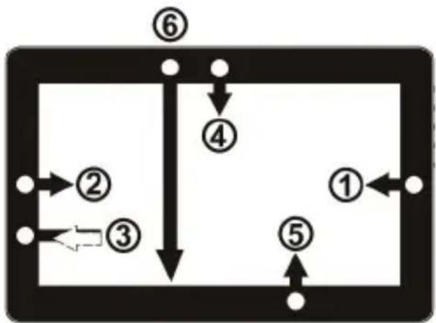
Common Touch Gesture Introduction:
- Use finger to swipe in from edge:
① Swipe in from the right edge of the screen (Arrow 1): Open the five charms – Search, Share, Start, Devices, and Settings
② Swipe in from the left edge of the screen (Arrow 2): Switch between apps
③ Swipe in from the left edge of the screen then out toward the left edge of the screen (Arrow 3): Display all apps
flowchart
graph TD
    ① --> ②
    ② --> ③
    ③ --> ④
    ④ --> ⑤
    ⑤ --> ⑥
    ⑥ --> ⑦
    ⑦ --> ⑧
    ⑧ --> ⑨
    ⑨ --> ⑩
    ⑩ --> ⑪
    ⑪ --> ⑫
    ⑫ --> ⑬
    ⑬ --> ⑭
    ⑭ --> ⑮
    ⑮ --> ⑯
    ⑯ --> ⑰
    ⑰ --> ⑱
    ⑱ --> ⑲
    ⑲ --> ⑳
    ⑳ --> ⑴
    ⑴ --> ⑤
    ⑤ --> ⑥
    ⑥ --> ⑦
    ⑦ --> ⑧
    ⑧ --> ⑨
    ⑨ --> ⑩
    ⑩ --> ⑪
    ⑪ --> ⑫
    ⑫ --> ⑬
    ⑬ --> ⑭
    ⑭ --> ⑮
    ⑮ -.->|loop| ③
    ③ -.->|loop| ②
④⑤Swipe in from the top edge (Arrow 4) or bottom edge (Arrow 5): Display commands of app, like Add New, Reminder, etc.
⑥With touch, drag the app from the top edge of screen (Arrow 6) to the bottom of the screen: Close app
-
Select item: Tap on the item to open. This function is similar to clicking on mouse.
-
Press and hold the item for a few seconds then release: Display item information. This function is similar to right-clicking on mouse.
13
- Zoom in and out: Touch the item with two fingers then move fingers toward each other (pinch) or away from each other (stretch).
- Slide finger on the screen, horizontally or vertically, to move through content. This function is similar to scrolling with a mouse.
Chapter 4 Hot Keys and OSD Instructions
Section 1 Hot Keys and LED Light Description
*Notice: If need to adjust "Increase/up" or "Decrease/down" continuously, press the button and hold. Do not press two buttons at the same time, due it may cause no response or fault response.
LED Lights Description :
It shows green light when turn on On-Lap Monitor and shows red light when stand by.
Hot Keys Description
Power: Press the Power Button can power on/off the Monitor.
Exit/Auto Adjustment: In the OSD panel, press the Exit Button to exit and back to the previous page. When there is no OSD menu, press this Button will activate automatic adjustment function (only pertains to analog VGA signal)
Menu/Select: Press the Menu Button to launch OSD panel.
Increase Volume/UP: Press this Button to increase the volume of speakers. If the OSD menu is launched, press this button will move up or move left the list. Press and hold for automatic continuous increase.
Decrease Volume/Down: Press this Button to decrease the volume of speakers. If the OSD menu is launched, press this button will move down or move right the list. Press and hold for automatic continuous decrease.

text_image
Power On/Off Power On/Off Indicator Exit/Auto Menu/Select Volume Up/Up Volume Down/DownSection 2 OSD Description
1. Basic Button Operation
Press 📄 button to launch the OSD panel. Press 🔒 or Ⓧ to view the functions. To adjust a certain function, press 🔊 to launch it. If the selected function consists of sub-menu, press 🔒 or Ⓧ again to view the sub-menu. When the desired function is highlighted, press 🔊 to launch it. Press 🔒 or Ⓧ to change the setting. To exit, press 🔊 to exit. Repeat the preceding steps to adjust other setting.
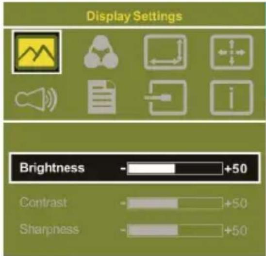
2. Display Settings
As shown in Fig., after Display Settings is launched, can adjust Brightness, Contrast, and Sharpness.
text_image
Display Settings Brightness - +50 Contrast - +50 Sharpness - +503. Color Setting
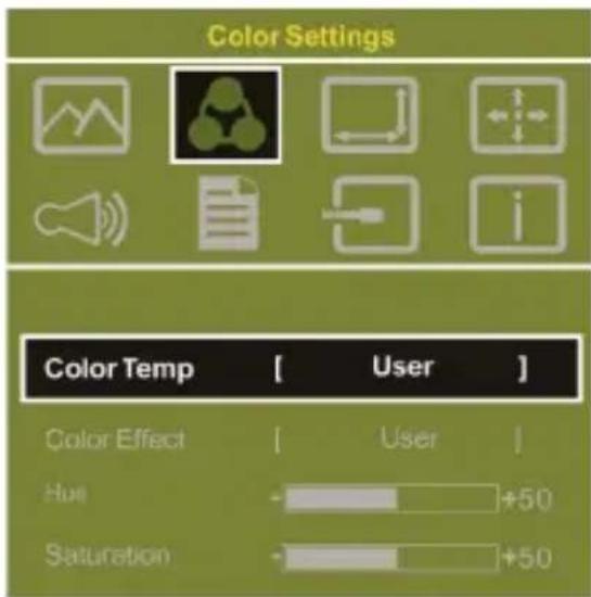
As shown in Fig., after Color Settings is launched, can adjust Color Temp and Color Effect to adjust screen color setting. Hue setting can make the image color lean toward green or purple
Saturation setting can make saturation more vivid or more black and white.
text_image
Color Settings Color Temp [ User ] Color Effect [ User ] Hue +50 Saturation +50At Color Temperature, select "User", can adjust RGB color setting, please refer to Fig. Select "Cool" can increase the blue saturation of the image. Select "Warm" can increase the red saturation of the image. At Color Effect, select "Standard", "Game", "Movie", "Photo" or "Vivid"
Select "User" can adjust the Hue and Saturation of Red/Blue/Green/Cyan/Yellow/Magenta
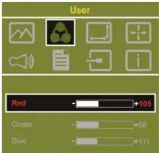
text_image
User Red +105 Green +88 Blue +1114. Aspect Ratio
Please refer to Fig. Suggested setting is 16:9. When HDMI image is 4:3 format, can select 4:3, make image not enlarge to 16:9 and change shape. Using VGA image input won't have this function Notice: When use 4:3 setting, the left and right sides of On-Lap 1503 will show black frame. Because its not full screen image display, thus image location and press signal location will not be the same, will not be able to press the correct
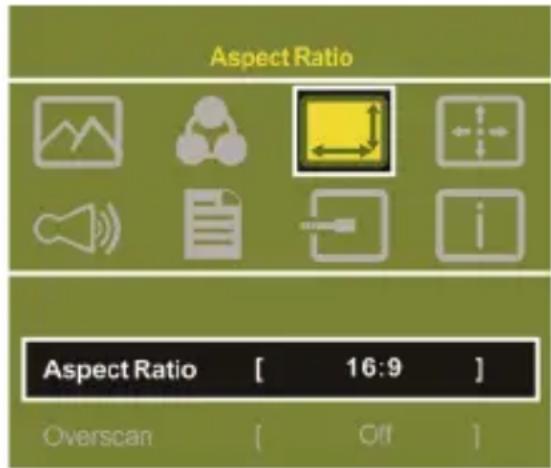
text_image
Aspect Ratio Aspect Ratio [ 16:9 ] Overscan [ Off ]Overscan: Only when input HDMI Video signal (ex. 1080P/720P), can use such function. Use this function can adjust the image scan area.
5. Manual Image Adjust
Auto Adjust: Only when input VGA signal can use such function. Will automatically adjust VGA setting
H.Position: Moves the display area left and right.
V.Position: Moves the display area up and down
Clock: Adjust the pixel clock for user's preference
Phase: Adjust the pixel phase for user's preference
- Audio: Adjust volume or select mute
- OSD Menu
OSD Timer: Adjust OSD Time
OSD H. POS: Moves OSD left and right
OSD V. POS: Moves OSD up and down
OSD Transparency: Makes OSD transparent
Language: Select OSD language
Reset: Restore to factory setting
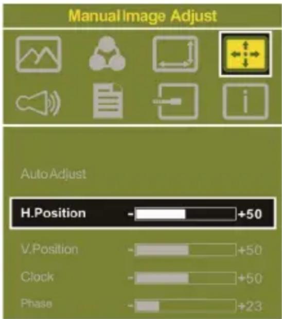
text_image
Manual Image Adjust Auto Adjust H.Position - +50 V.Position - +50 Clock - +50 Phase - +23- Input Source: Select VGA signal source, HDMI 1 digital signal (input from the left HDMI port), HDMI 2 digital signal (input from the back Dock connector) or AUTO Detect.
- Information: Display factory version
Section 3 Low Power Protection Warning
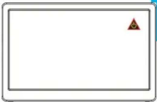
If the volume setting is too high, the power requirement may be higher than the power provided by computer or 5V DC Charger. At this time, the Low Power Protection Warning will appear. Please reduce the volume immediately. And connect the two USB connectors of USB Cable to the two USB ports on computer. If the volume is not reduced in time, the Monitor will decrease the volume and brightness automatic
natural_image
Blank white rectangle with a small red triangular warning symbol in the top-right corner (no text or symbols on the main area)Chapter 5 Specification
Section 1 Plug and Play
The On-Lap Monitor conforms to VESA DDC standard and supports VESA DDC2. DDC2B is a bi-directional data channel based on I ^2 C protocol. The host can request EDID information over the DDC2B channel. The On-Lap Monitor is able to inform the host system of its identity, and depending on the level of DDC used, communicate additional information about its display capabilities.
Section 2 Pin Assignment
- HDMI Connector Pinout
| Pin | Name | Pin | Name |
| 1 | TMDS Data2+ | 11 | TMDS Clock Shield |
| 2 T | TMDS Data2 Shield 12 | TMDS Clock – | |
| 3 | TMDS Data2 – | 13 | Reserved |
| 4 T | TMDS Data1+ 14 | Reserved | |
| 5 | TMDS Data1 Shield | 15 | SCL (I2C Serial Clock for DDC) |
| 6 | TMDS Data1 – | 16 | SDA (I2C Serial Data Line for DDC) |
| 7 | TMDS Data0+ | 17 | DDC Ground |
| 8 | TMDS Data0 Shield | 18 | +5 V Power |
| 9 | TMDS Data0 – | 19 | Hot Plug Detect |
| 10 | TMDS Clock+ |
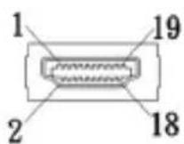
Fig.: HDMI-A Connector (Connect to HDMI port)
- VGA Connector Pinout
| Pin No. | Name | Pin No. | Name | Pin No. | Name |
| 1 | RED | 6 | RGND | 11 | NC |
| 2 | GREEN | 7 | GGND | 12 | SDA |
| 3 | BLUE | 8 | BGND | 13 | HSYNC |
| 4 | NC | 9 | +5V | 14 | VSYNC |
| 5 | GND | 10 | SGND | 15 | SCL |
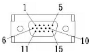
text_image
1 5 6 11 15 10Fig.: VGA connector
Section 3 Specification
| Model On-Lap 1503I On-Lap 1503H | On-Lap 1503A | ||
| Panel | 15.6" FHD TFT (16:9 Wide) LED Backlight | 15.6" FHD TFT (16:9 Wide) LED Backlight | 15.6" HD TFT (16:9 Wide) LED Backlight |
| Resolution /Color depth | 1920x1080 /262K colors | 1920x1080 /262K colors | 1366x768 /262K colors |
| Viewing Angle (Typical) | 160°(H)/160°(V) 160° | (H)/160°(V) | 45°/20°/45°/45° (Up/Down/Left/Right) |
| Contrast Ratio (Typical) | 700:1 700:1 500:1 | ||
| Response Time (Typical) | 12.5(ms) 12.5(ms) | 8(ms) | |
| Touch Technology | Projected capacitive touch screen; 10-point multi-touch; Input by fingers. Support Windows 10/8.1/7 | No touch screen No touch screen | |
| Screen Coating | Touch screen hardness ≥7H | No touch screen No touch screen | |
| Resolution Specification | 1920*1080(60Hz/50Hz),1600*900(60Hz),1440*900(60Hz),1366*768 (60Hz),1280*1024(60Hz),1280*960(60Hz),1280*800(60Hz/50Hz),1280*768 (60Hz/50Hz),1280*720(60Hz/50Hz),1024*768(60Hz), | ||
| HDMI Video Display Capabilities | 1080P(60Hz/50Hz);1080i(30Hz/25Hz); 720P(60Hz/50Hz); (HDCP Compliant) | ||
| Speakers 1.0W | (Max.)x 2 1.0W (Max.)x 2 | 1.0W (Max.)x 2 | |
| Rating Voltage/Current | 5V 2A(Max.) | 5V 2A(Max.) | 5V 1.5A(Max.) |
| Dimension (Typical) | 382mm*245mm*12mm (Without Cover and Stand) | 382mm*245mm*11mm (Without Cover and Stand) | 382mm*245mm*11mm (Without Cover and Stand) |
| Weight (Typical) | 1,064g (Monitor) 282g(Stand) 290g(Cover) | 798g (Monitor) 282g(Stand) 290g(Cover) | 812g (Monitor) 282g(Stand) 290g(Cover) |
| Safety |  | ||
Section 4 Trouble Shooting
- Image, Audio, touch or other troubles
| Problem | Solution |
| No response when finger touches on the monitor | 1. Check if USB Touch Power Cable plug 1 is connected to computer's USB port. The 2 USB plug of USB Touch Power Cable cannot transmit touch signal. (Refer to Chapter 2> Section 2)2. Check if the computer installs Window 10 or Windows 7. |
| While touching On-Lap 1503I, the cursor works on the main display, not 1503I. | Please set up from "Tablet PC Setting" (Windows 10/7) to calibrate the touch monitor. (Refer to Chapter 3> Section 3) |
| Touch function malfunctions sometime. Function recovers after restarting | USB signal transmission might be broken off because USB port may not provide sufficient power. Please connect both USB-A plugs into USB ports of laptop/5V-2A adapter. |
| No image or OSD displays "No Signal" warning | 1. Check if Power On/Off Indicator shows green light. If not, it means no power connection. Please refer to user manual instruction to connect power.2. Check if VGA/HDMI Video Cable is connected between On-Lap's connector port and computer's connector port.3. Check if Micro HDMI Video Cable connector is accidentally connected to the VGA port/ DisplayPort port on On-Lap.4. Please adjust "Brightness" and "Contrast" in OSD setting. |
| Image flicks or blinks and recover later | Please avoid pulling video cable. Please connect both Y-type USB-A plugs into USB ports to make sure the power supply is sufficient. |
| Monitor has image but no sound | 1. Press "Up" button to increase audio level.2. Use of VGA input will not have audio signal.3. Check Sound Setting of the computer. Choose output to HDMI device.4. 1503 only supports audio out by phone jack. The phone jack doesn't support audio in function. |
| Problem Solution | |
| Monitor reboots or monitor displays Low Power Protection Warning | Because the output current is greater than the input current, please lower the audio and brightness level. Connect the two USB connectors of Micro USB Touch and Power Cable to the two USB ports on the computer to increase power. Or using 5V 2A Charger to supply power. |
- The unavailability of “Duplicate these displays” or “Extend these displays” in Display setting may be limited by the graphics chip of the laptop or have the graphic chip features limited due to the power saving mode of the laptop or have the graphic chip driver updated. Please consult your laptop manufacturer or graphic chip manufacturer.
第一章 内容物の解説
その1. モニタ本体と付属品
- 各部の説明
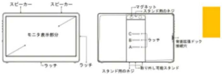
natural_image
Line drawing of a foldable electronic device with a flat panel and stand (no text or symbols)B. 縱表示
flowchart
graph LR
    A["Device with battery and adjustment"] --> B["Assembly"]
    B --> C["Screen with monitor and cable"]
    style A fill:#f9f,stroke:#333
    style B fill:#ccf,stroke:#333
    style C fill:#cfc,stroke:#333
natural_image
Technical line drawing of an electrical enclosure and its internal wiring (no text or symbols)図:モバイルバッテリーの取り付け
natural_image
Technical line drawing of a mechanical part with two numbered annotations (① and ②) and directional arrows indicating movement or assembly (no text or symbols on the diagram itself)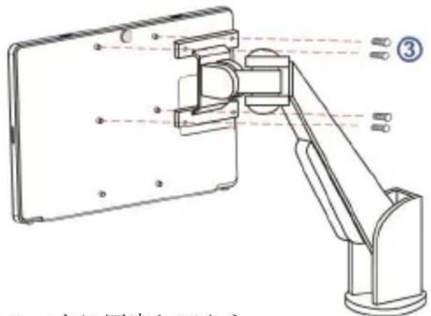
text_image
Technical diagram of a mechanical arm assembly with labeled components and Chinese text describing the assembly.text_image
Technical diagram showing a device with labeled components and directional arrows, including numbered callouts ① and ②.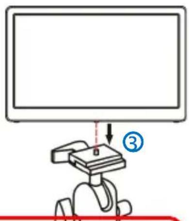
text_image
Diagram showing a robot interacting with a monitor, labeled with number ③ and directional arrownatural_image
Two 3D-rendered objects with black and white cutouts, no text or symbols visible図:Stand4 組み付け
natural_image
Simple line drawing of a flat-screen monitor with a yellow rectangle on the right side (no text or symbols)natural_image
Blank white rectangular frame with a small red triangular warning symbol in the top-right corner (no text or symbols on the main area)図:電力低下時の警告表示
第五章 製品仕様
その 1・プラグアンドプレイ