
DFR22 - Processor SHURE - Free user manual and instructions
Find the device manual for free DFR22 SHURE in PDF.


| Product Type | Digital Audio Processor with Feedback Reduction |
| Brand | Shure |
| Model | DFR22 |
| Dimensions (W x D x H) | 482.6 mm x 247.7 mm x 44.4 mm |
| Weight | 2.83 kg |
| Power Supply | 100–240 V AC, 50/60 Hz, automatic switching, 1 A maximum |
| Maximum Power Consumption | 45 W |
| Frequency Response | 20 Hz to 20 kHz ± 1 dB |
| Sampling Frequency | 48 kHz |
| Conversion Resolution | 24-bit |
| Input Impedance | 10 kΩ |
| Output Impedance | 120 Ω |
| Input Clipping Level | +24 dBu minimum |
| Output Clipping Level | +24 dBu (no attenuation), +12 dBu (12 dB attenuator), +6 dBu (18 dB attenuator) |
| Total Harmonic Distortion | < 0.05% at +4 dBu, 20 Hz to 20 kHz |
| Input/Output Propagation Delay | < 1.5 ms |
| Number of Inputs/Outputs | 2 inputs, 2 outputs (Phoenix and XLR connectors) |
| Main Functions | Digital feedback reduction, graphic and parametric equalizer, delay up to 10 s, compression, clipping, limiting, automatic gain control, 2-way crossover filter, 2x2 matrix mixer |
| Connectivity | RS-232 (DB9 front, Phoenix rear), Shure Link (5-pin DIN), control inputs (6-pin Phoenix) |
| Presets | 3 factory presets, up to 16 presets |
| Included Accessories | Power cable, ShureLink 5-pin DIN cable, 4 mounting screws, 5 3-pin plug-in terminals, 1 6-pin plug-in terminal, software CD-ROM |
| Optional Accessories | DRS10 (wall-mounted preset control unit) |
| Maintenance and Cleaning | Clean only with a dry cloth. Do not use liquids. |
| Safety | Do not expose to water or moisture. Do not block ventilation openings. Disconnect during storms. Refer all repairs to qualified personnel. |
| Repairability / Spare Parts | No user-serviceable parts. Contact Shure customer service for repairs. |
| Certifications | UL, cUL, FCC Class B, ICES-003, CE, EN60065, EN55103 |
| Operating Conditions | -7 °C to 49 °C |
| Storage Conditions | -29 °C to 74 °C |
Frequently Asked Questions - DFR22 SHURE
User questions about DFR22 SHURE
0 question about this device. Answer the ones you know or ask your own.
Ask a new question about this device
Download the instructions for your Processor in PDF format for free! Find your manual DFR22 - SHURE and take your electronic device back in hand. On this page are published all the documents necessary for the use of your device. DFR22 by SHURE.
USER MANUAL DFR22 SHURE
DFR22
Audio Processor with Feedback Reduction
! IMPORTANT SAFETY INSTRUCTIONS!
- READ these instructions.
- KEEP these instructions.
- HEED all warnings.
- FOLLOW all instructions.
- DO NOT use this apparatus near water.
- CLEAN ONLY with dry cloth.
- DO NOT block any ventilation openings. Install in accordance with the manufacturer's instructions.
- DO NOT install near any heat sources such as radiators, heat registers, stoves, or other apparatus (including amplifiers) that produce heat.
- DO NOT defeat the safety purpose of the polarized or grounding-type plug. A polarized plug has two blades with one wider than the other. A grounding type plug has two blades and a third grounding prong. The wider blade or the third prong are provided for your safety. If the provided plug does not fit into your outlet, consult an electrician for replacement of the obsolete outlet.
- PROTECT the power cord from being walked on or pinched, particularly at plugs, convenience receptacles, and the point where they exit from the apparatus.
- ONLY USE attachments/accessories specified by the manufacturer.
12.

USE only with a cart, stand, tripod, bracket, or table specified by the manufacturer, or sold with the apparatus. When a cart is used, use caution when moving the cart/apparatus combination to avoid injury from tip-over.
- UNPLUG this apparatus during lightning storms or when unused for long periods of time.
- REFER all servicing to qualified service personnel. Servicing is required when the apparatus has been damaged in any way, such as power-supply cord or plug is damaged, liquid has been spilled or objects have fallen into the apparatus, the apparatus has been exposed to rain or moisture, does not operate normally, or has been dropped.
- DO NOT expose the apparatus to dripping and splashing. DO NOT put objects filled with liquids, such as vases, on the apparatus.
- The MAINS plug or an appliance coupler shall remain readily operable.
- The airborne noise of the apparatus does not exceed 70dB (A).
- Apparatus with CLASS I construction shall be connected to a MAINS socket outlet with a protective earthing connection.
- To reduce the risk of fire or electric shock, do not expose this apparatus to rain or moisture.
- Do not attempt to modify this product. Doing so could result in personal injury and/or product failure.

This symbol indicates that there are important operating and maintenance instructions in the literature accompanying this unit.

This symbol indicates that dangerous voltage constituting a risk of electric shock is present within this unit.
WARNING: Voltages in this equipment are hazardous to life. No user-serviceable parts inside. Refer all servicing to qualified service personnel. The safety certifications do not apply when the operating voltage is changed from the factory setting.
WARNING: This product contains a chemical known to the State of California to cause cancer and birth defects or other reproductive harm.
! CONSIGNES DE SÉCURITÉ IMPORTANTES !
The DFR22 Audio Processor with Feedback Reduction is a 2-input, 2-output digital audio processor. It is designed to equalize sound system response, provide dynamics processing and alignment delay, and automatically detect and control acoustic feedback. A built-in 2 X 2 matrix mixer allows either or both inputs to be routed to either or both outputs, with additional controls for levels and polarity.
The DFR22 is ideal for installed sound reinforcement applications, such as houses of worship, theaters, and meeting facilities. It is also a powerful setup tool in live music applications. Using the DFR22's drag-and-drop graphical user interface, processors can be placed anywhere in the signal path.
DFR22 Features
- Shure's patented digital feedback reduction algorithm:
- Now includes stereo DFR processing capability
- New Auto Clear mode clears dynamic filters after a pre-set change or power cycle. Dynamic filters can be automatically removed after a specified number of hours.
- Configurable signal path with drag and drop Windows interface. Includes graphic and parametric EQ, up to 10 seconds of delay, compression, limiting, gating, automatic gain control, ducking, and a fully configurable two-way crossover.
• Phoenix and XLR connectors for each input and output - Compatible with USB to serial port converters.
•Front and back panel RS232 ports:
- 3-pin Phoenix connector on back panel.
- DB9 connector on front panel; requires only TX, RX, and GND to be connected.
- Three pre-loaded presets:
– Preset 1: Two mono 16 filter DFRs.
– Preset 2: A stereo 16 filter DFR.
– Preset 3: A mono 16 filter DFR on each input. Each input is routed to each output.
- Preset selector and indicator for up to 16 presets
•Control input pins for setting up remote preset, volume, and mute controls
PACKING LIST
•Power Cable
-5-pin DIN ShureLink Cable
•4 Rackmount Screws with Nylon Washers
- Five 3-Pin Block Connector Terminals (for audio input/output and RS-232 communication)
•One 6-pin Block Connector Terminals (for control inputs)
•One DFR22 Software CD-ROM and Online User Guide
REQUIREMENTS
Power Requirements
•100–240 Vac, 50/60 Hz
- 45 W maximum
Computer Requirements
- 20 MB of hard drive space
- CD ROM drive
- RS-232 serial port and cable, or approved USB-to-Serial port adapter*
•VGA monitor with 640 x 480/256 color, or higher resolution - Mouse or other pointing device
NOTE: Processor speed and memory requirements vary, depending on the version of Windows and number of background applications you are running. Operating the DFR22 software simultaneously with programs such as SIA–Smaart ^® or Gold Line TEF ^™ requires a faster processor and more RAM. The chart below lists the minimum requirements for running the DFR22 software with no other applications—including virus protection, firewall, instant messaging, or email—in the background.
| Windows Version Processor Speed RAM | |
| 98, Second Edition Pentium 166 MHz 48 MB | |
| NT Pentium 233 MHz 64 MB | |
| ME Pentium 300 MHz 64 MB | |
| 2000 Professional Pentium 300 MHz 96 MB | |
| XP Professional, Home Pentium 300 MHz 128 MB |
*Most USB-to-serial port adapters work well with the DFR22. To see the latest list of fully approved adapters, visit http://shure.custhelp.com/app/answers/detail/a_id/2951
SOFTWARE INSTALLATION
- Insert supplied CD into your CD-ROM drive and follow the on-screen instructions.
-
If installation does NOT start automatically, click on the [Start] button the Windows taskbar and select [Run...] from the pop-up menu.
-
Type [D:/setup}, where "D" is your CD-ROM drive letter.
- Click OK and follow the on-screen instructions.
USING THE DFR22 SOFTWARE
Instructions for the DFR22 software are available in PDF format on the CD-ROM included with the system, or on the Shure web site at www.shure.com.
NOTE: Register this product by filling out and mailing the enclosed registration card, or register online at the Shure web site (www.shure.com). Registration allows you to receive information about software updates as they become available.
OVERVIEW
Front Panel

DFR22 FRONT PANEL
Figure 1
1. INPUT/OUTPUT Level Meters:
- CLIP. Illuminates at 3 dB below clipping level.
- 0 V+4 dBu, -10 dBV; software selectable. 0 dB is equal to +4 dBu by default. If the input or output sensitivity is changed to -10 dBV using the DFR22 software, 0 dB equals -10 dBV.
--20 dB. Illuminates when the signal meets or exceeds the indicated level.
- MUTE. Illuminates when input or output is muted.
- DFR Filter LEDs. Illuminate when individual feedback filters are active. When a filter changes or is added, an LED flashes, then stays on.
- AUTO CLEAR Buttons and LEDs. Press and release these buttons to configure Auto Clear mode for each channel. Press them again to activate Auto Clear. When an Auto Clear LED illuminates, Auto Clear is active on its corresponding channel.
-
PRESS TO LOCK / HOLD TO CLEAR Button and LEDs. Press this button to lock filters at their current values. Holding this button down will reset all feedback filters, even if they are locked. The LED lights to indicate that the lock is active.
-
BYPASS DFR FILTERS Button and LEDs. Press these buttons to suspend feedback reducer operation and remove feedback filters from the audio path. When a Bypass LED illuminates, feedback reduction is bypassed on the corresponding channel. Bypass does not affect other processors (such as equalizers, delay, limiters, etc.).
- LOAD Button. Press this button to activate a selected preset.
- PRESET Indicator. Shows the number of the currently active preset. Blinks to show the number of the other presets in the DFR22 when pressing the SELECT buttons.
- SELECT Buttons. Press to scroll through the presets stored in the DFR22.
- COMM LED. Flashes in unison with the feedback filter LEDs when the detector is deploying a new filter or changing an existing one, and also blinks whenever the unit is communicating with a connected computer.
- RS232 Port. Connects the DFR22 to a computer.
- POWER LED. Illuminates when 100–240 VAC power is applied to the DFR22.
Back Panel

DFR22 REAR PANEL
Figure 2
- Power Connector. Connects to 100–240 VAC power.
- Shure Link Interface. Allows linking of up to 16 Shure Link devices, which may be accessed by a computer.
- 3-Pin RS-232 Port. Connects the DFR22 to a computer. For use with DFR22 software and control systems. Refer to the Computer Connections section.
- CONTROL IN Pins. Use control input pins for remote control of preset switching, muting, and gain. Refer to the Control Pin Connections section.
- DIP Switches. Use Switches 1–4 to select a Shure Link Device ID. Use Switch 5 to lock or unlock front panel controls. Refer to the Front Panel Lockout section for information on locking front panel controls.
-
Output Connectors (Phoenix). These active, cross-coupled, balanced outputs can be used with balanced or unbalanced inputs. They can be switched between +4 dBu/-10 dBV line-level operation, using the DFR22 software. Refer to the Audio Connections section.
-
Output Connectors (XLR). These active, cross-coupled, balanced outputs can be used with balanced or unbalanced inputs. They can be switched between +4 dBu/-10 dBV line-level operation using the DFR22 software. Refer to the Audio Connections section.
- Input Connectors (Phoenix). These active balanced inputs can be used with balanced or unbalanced outputs. They cannot be used simultaneously with an XLR connector for the same input. They can be switched between +4 dBu/-10 dBV line-level operation using the DFR22 software. Refer to the Audio Connections section.
- Input Connectors (XLR). These active balanced inputs can be used with balanced or unbalanced outputs. They cannot be used simultaneously with a Phoenix connector for the same input. They can be switched between +4 dBu/-10 dBV line-level operation using the DFR22 software. See Audio Connections section for more information.
- POWER Switch
Note: Country dependent
DEFAULT PRESETS
The DFR22 comes with three factory-configured presets. Although a computer is required to configure the DFR22's equalizers, dynamics processors, delays, and crossover, you can use the DFR22 "out of the box" as an automatic feedback reducer, without connecting it to a computer.
Preset 1: Provides two independent feedback reducers. The audio signal going to Input 1 is analyzed and filtered by a feedback reducer using up to 16 notch filters, and is then routed to Output 1. Input 2 is analyzed by another feedback reducer and then routed to Output 2. On the front panel, Row A of the DFR Filters and controls is assigned to the feedback reducer on Input 1; Row B is assigned to the feedback reducer on Input 2.
FRONT PANEL CONTROL FUNCTIONS
Auto Clear
By default, the DFR22 saves all feedback filters during a preset change or power cycle. However, you can configure the device to automatically remove dynamic feedback filters and changes to the depth of fixed feedback filters, according to parameters that you specify.
Each time the DFR22 detects a feedback frequency, it assigns that frequency to one of the filters. By default, the first eight frequencies are assigned to fixed filters, and the second eight are assigned to dynamic filters. Both types of filters can deepen if feedback reoccurs at the same frequency. The frequency of a fixed filter will not change unless you manually clear all of the filters. However, if all filters are in use and an additional feedback frequency is detected, the DFR22 replaces the oldest existing dynamic filter with a new filter at a new frequency.
Establishing the Auto Clear Function. To establish the Auto Clear function, proceed as follows:
NOTE: The procedure for setting up the Auto Clear function using the front panel controls differs slightly from the procedure in the DFR22 Windows software.
- Ring out the sound system to set any feedback filters that you want to be a permanent part of the system equalization.
- Press the Auto Clear button on the DFR22 front panel. The Auto Clear button will blink. Auto Clear will automatically redesignate any engaged filters as fixed and the rest as dynamic. For example, if you have five filters set, Auto Clear will designate those as fixed and will designate the remaining 11 filters as dynamic.
- The preset indicator will display a flashing [-h]. If you want Auto Clear to work automatically after a certain number of hours, you must use the Preset Select buttons to set the number of hours (1 to 99). Each filter has its own timer, starting from the time it is set or changed. If you leave the preset indicator at [-h], Auto Clear will only work on a preset change or power cycle.
- Press either the LOAD button or the AUTO CLEAR button again. The AUTO CLEAR LED will glow steadily.
- When a preset is changed, or if power is turned off and on, the DFR filters will return to the state they were in when Auto Clear was engaged. If a number of hours was specified, each dynamic filter and change to the depth of each fixed filter will be removed that many hours after it is set.
Disengaging the Auto Clear Function. To disengage the Auto Clear function, press the AUTO CLEAR button again. The Auto Clear LED will go out, and the number of fixed filters and dynamic filters will reset to eight of each type.
NOTE: Holding the clear button down while Auto Clear is engaged will only clear the dynamic filters.
Preset 2: Provides a stereo feedback reducer. Signal going into each input is analyzed independently, but the feedback reducer applies the same notch filters to each channel. As with Preset 1, Row A of the DFR filters and controls on the front panel is assigned to the feedback reducer on Input 1; row B is assigned to the feedback reducer on Input 2. Because the feedback reducers always apply the same filters to both channels, the DFR filter indicators and controls are linked.
Preset 3: Similar to Preset 1, except both inputs are routed to both outputs.
Press to Lock / Hold to Clear
Pressing these buttons locks the filters at their current values. If Auto Clear is not engaged, holding them down for three seconds resets all filters. If Auto Clear is engaged, holding them down only resets dynamic filters. When the PRESS TO LOCK/HOLD TO CLEAR LEDs are illuminated, the Lock function is engaged and no filters can be added or changed. Also, the Auto Clear timer is suspended.
Bypass DFR Filters
Pressing the DFR BYPASS button suspends the feedback reducer operation and bypasses existing feedback filters. It does NOT affect any other processors. When the DFR BYPASS LED illuminates, the feedback reducer is disengaged.
Changing Presets
The Preset Indicator on the front panel displays the number of the active preset. You can scroll through all presets stored in the device. By pressing the arrow keys on the preset selector. When you select a preset number, the display blinks. If you press the LOAD button within five seconds, the device will make the selected preset the new Live preset. If you do not press the LOAD button, the preset will not change and the display will return to the original Live preset.
The preset indicator and controls are also used for setting the number of hours after which each dynamic filter is removed when engaging Auto Clear.
Front Panel Lockout
When this DIP switch is in the "Unlock" position, all front panel controls are enabled. When it is in the "Lock" position, all front panel controls are disabled. However, all front panel indicators still function and show the state of each parameter.
You can override this DIP switch using the DFR22 software and individually enable or disable each button on the front panel of the DFR22. Access to the DFR22 via a computer can only be disabled by setting the appropriate security level through the DFR22 software.
DFR22 Theory
Feedback Reduction
No sound system (microphones + mixing/signal processing + power amplifiers/loudspeakers + room acoustics) has an absolutely flat frequency response. When the level of a sound system is increased, the frequencies at which peaks occur will be the first to exceed the feedback threshold. The DFR22 attenuates these frequencies, flattening the response of the sound system. The system can then operate at a higher overall level.
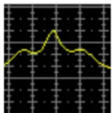
The DFR22 includes Shure's patented Adaptive Notch Filter algorithm that can discriminate between feedback and non-feedback sounds. When this algorithm detects feedback, it inserts a shallow, narrow filter into the audio path, reducing gain at the frequency that is feeding back. (See Figure 3.) This filter is called a notch filter, since it affects a narrow section of the audio spectrum. If the feedback does not stop, the filter depth is increased. By default, filters in the DFR22 are deployed as HIGH Q filters. As a High Q filter gets deeper, its Q increases up to a Q of 101 (1/70th of an octave). Using the DFR22 software, you can also set filters to deploy as LOW Q. Low Q filters affect a slightly wider range of frequencies by maintaining a Q of 14.42 (1/10th of an octave) as they deepen. By default, the DFR22 can insert up to 16 notch filters per channel to reduce feedback.
The DFR22's feedback reduction algorithm can be used as a tool during system setup and for peace of mind against unexpected feedback. When setting up a sound system with the DFR22, you can ring out the system by slowly raising the gain while talking into the microphones until the first frequency begins to feed back. The DFR22 will automatically insert a notch filter to attenuate that frequency. Once the system stops feeding back, you can further raise the level and repeat the process for additional frequencies. Typically, you can raise the gain 3 – 9 dB above the level at which feedback first occurred. You should leave some filters available to catch feedback that might occur later, when the sound system is in use.
line
| Time | Value | |------|-------| | 0 | 0 | | 1 | 1 | | 2 | 2 | | 3 | 3 | | 4 | 4 | | 5 | 3 | | 6 | 2 | | 7 | 1 | | 8 | 0 |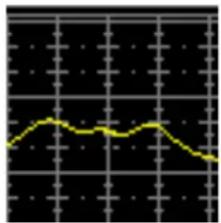
line
| Time | Value | |------|-------| | 0 | 0.5 | | 1 | 0.6 | | 2 | 0.7 | | 3 | 0.8 | | 4 | 0.9 | | 5 | 1.0 | | 6 | 0.9 | | 7 | 0.8 | | 8 | 0.7 | | 9 | 0.6 | | 10 | 0.5 |Measured Frequency Response with Peak Measured Frequency Response with Notch Filter Added
EFFECTS OF NOTCH FILTER ON FREQUENCY RESPONSE
Figure 3
DFR22 Limitations
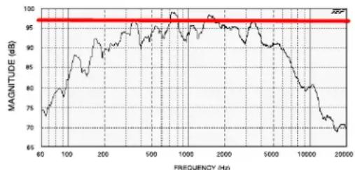
The DFR22 (or any other feedback reduction processor) will not let you to increase gain beyond the physical limits of the sound system. In most cases, the point of diminishing returns is reached once 5 to 8 notch filters have been set. This is because there are usually only a few dominant peaks in a system's frequency response (Figure 4A). In most cases, you can expect a 6 to 9 dB improvement in gain-before-feedback. When you are ringing out a system and notice that many frequencies feed back simultaneously, even when you increase the gain slowly, you have reached the point of diminishing returns. If the system still has insufficient gain before feedback at this point, other changes must be made to the sound system, such as changing the placement of the microphones and/or loudspeakers.
line
| FREQUENCY (Hz) | MAGNITUDE (dB) | | -------------- | -------------- | | 60 | 75 | | 100 | 85 | | 200 | 90 | | 500 | 95 | | 1000 | 98 | | 2000 | 97 | | 5000 | 95 | | 10000 | 85 | | 20000 | 70 |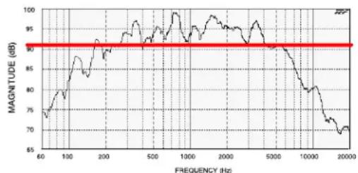
line
| FREQUENCY (Hz) | MAGNITUDE (dB) | | -------------- | -------------- | | 60 | 75 | | 100 | 85 | | 200 | 90 | | 500 | 95 | | 1000 | 98 | | 2000 | 95 | | 5000 | 90 | | 10000 | 80 | | 20000 | 70 |Figure 4A Figure 4B = Feedback Threshold
Use notch filters to lower peaks Lower overall system gain
FREQUENCY RESPONSE OF AN UNEQUALIZED SOUND SYSTEM
Figure 4
RACK MOUNTING THE DFR22
Mount the DFR22 in any standard 19-inch audio equipment rack, using the supplied screws. Refer to Figure 5.
NOTE: Avoid mounting wireless equipment and power amplifiers directly above or below the DFR22. Additional rack mount supports may be necessary for mobile installations.
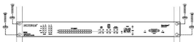
RACK MOUNTING THE DFR22
Figure 5
POWER AND INITIALIZATION
Power Mains Connections
Use the supplied power cable to connect the DFR22 Audio Processor to an active 100–240 Vac power source, as shown in Figure 6. The Power LED on the front panel will glow green when power is applied.

DFR22 POWER CONNECTION
Figure 6
Initialization
Once power is applied, the DFR22 Audio Processor takes approximately 5 seconds to initialize. When initialization is complete, the Input/Output LEDs will flash, as shown in Figure 7. The DFR22 is ready to use once the LEDs stop flashing.
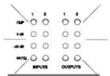
DFR22 INITIALIZATION
Figure 7
AUDIO CONNECTIONS
NOTE: Audio will pass from the inputs to the outputs, even if it has not yet been configured through the computer interface.
CAUTION: DO NOT connect equipment to both the Phoenix and XLR connectors of the same input or output at the same time. Doing so could damage the equipment.
Wiring Connectors
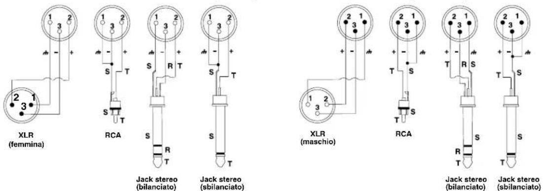
DFR22 XLR CONNECTORS (OUTPUT) DFR22 XLR CONNECTORS (INPUT)
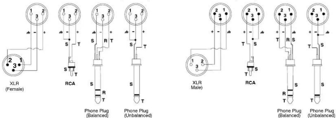
DFR22 PHOENIX CONNECTOR OUTPUTS / INPUTS
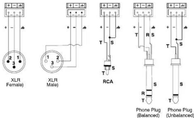
INPUT/OUTPUT CONNECTOR WIRING DIAGRAMS
Figure 8
12 dB and 18 dB Output Pads
Each DFR22 output has a 12 dB pad and an 18 dB pad that can be engaged through the software interface. Use these pads when connecting the DFR22 to lower-level inputs. They cannot be used to prevent clipping at the output stage of the DFR22
NOTE: The Output meters indicate the signal level present at the digital-to-analog converters. The 12 and 18 dB pads act upon the signal after the digital-to-analog converters, so the meters do not reflect the pads.
COMPUTER CONNECTIONS
RS-232 Connections
Connect the COM port on your computer to the 9-pin RS-232 connector on the front panel of the DFR22, shown in Figure 9, using a male-to-female serial cable. Pin outs for a 9-pin RS-232 cable are shown in Figure 10 and listed in Table 1.
NOTE: Only the TX, RX, and GND pins need to be connected in order to communicate with the DFR22.
You can also connect a computer or control system to the 3-pin RS-232 Phoenix connector on the back panel of the DFR22, as shown in Figure 11.
IMPORTANT: You CANNOT connect two PCs to the DFR22 at the same time. However, you CAN connect an AMX or Crestron system and a PC to the DFR22 at the same time.
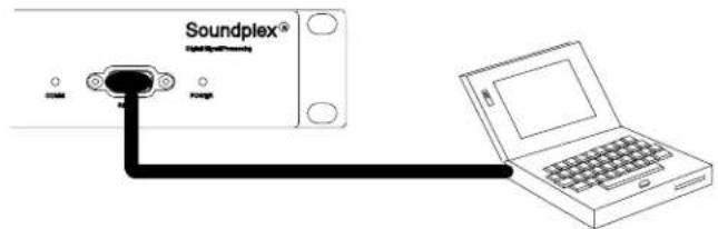
RS-232 SERIAL PORT CONNECTION Figure 9
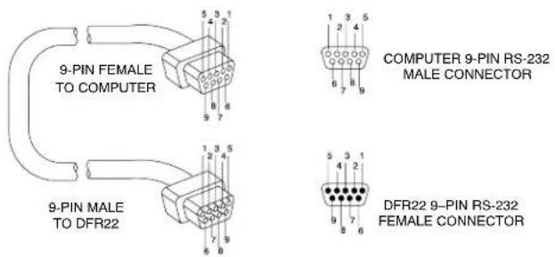
RS-232 CABLE PINOUTS Figure 10
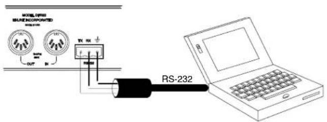
PHOENIX RS-232 SERIAL PORT CONNECTION Figure 11
Table 1. RS-232 PIN OUTS
| DFR22 COMPUTER PIN NO. | ||
| — — 1 | ||
| TX RX 2 | ||
| RX TX 3 | ||
| — DTR 4 | ||
| GND GND 5 | ||
| — DSR 6 | ||
| — RTS 7 | ||
| — CTS 8 | ||
| — — 9 | ||
Shure Link Network
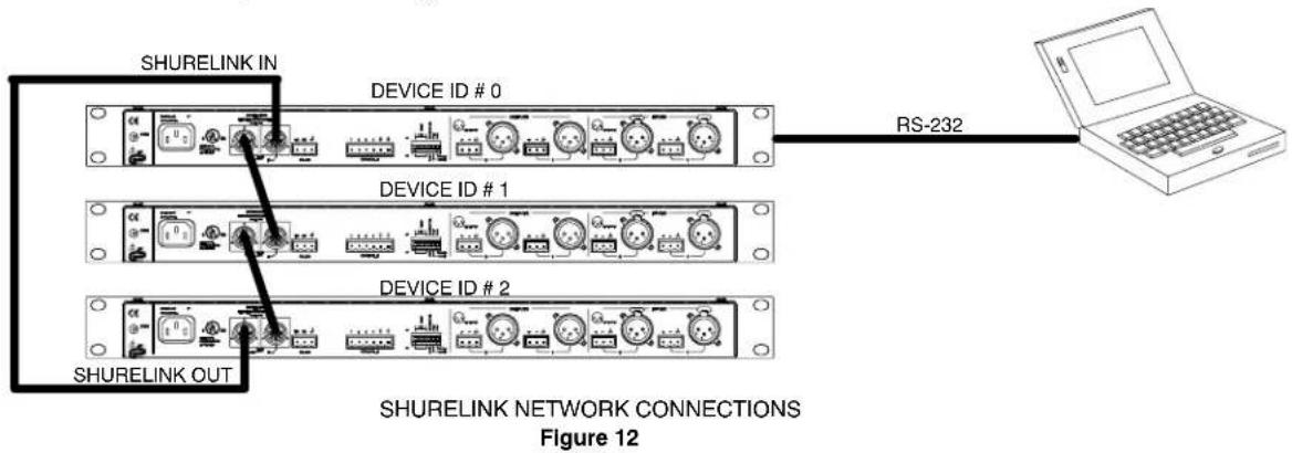
Up to 16 Shure Link devices, including the DFR22, DFR11EQ, DP11EQ, P4800, and UA888, can be linked and controlled from one computer. Using 5-pin DIN cables, connect the Shure Link IN and Shure Link OUT of each device, as shown in Figure 12.
NOTE: The last device in the chain MUST be connected to the first device (the one connected directly to the computer) to form a loop.
flowchart
graph TD
    A["SHURELINK IN"] --> B["DEVICE ID # 0"]
    B --> C["RS-232"]
    D["SHURELINK OUT"] --> E["DEVICE ID # 1"]
    E --> F["RS-232"]
    G["SHURELINK NETWORK CONNECTIONS"] --> H["Figure 12"]
DIP Switch Settings for Networked Devices
Assign each Shure Link device a unique Device ID Number, using DIP Switches 1–4, as shown in Figure 13. Refer to Table 2 for Device ID settings.
IMPORTANT: Each Shure Link device MUST have a unique Device ID number.
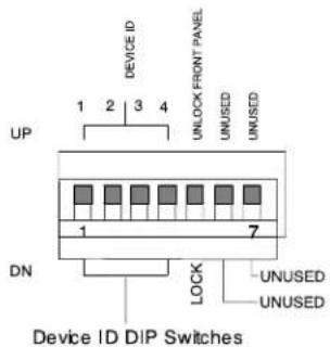
DIP SWITCH SETTINGS FOR NETWORKED DEVICES
Figure 13
Table 2. DEVICE ID SETTINGS
| Device ID | DIP Switch | Device ID | DIP Switch | |||||||
| 1 2 3 4 | 1 2 3 4 | |||||||||
| 0 DND | NDNDN8 | DNDNDNUP | ||||||||
| 1 UPD | NDNDN9 | UPDNDNUP | ||||||||
| 2 DNUP | DNDN10 | DNUPDNUP | ||||||||
| 3 UPUP | DNDN11 | UPUPDNUP | ||||||||
| 4 DND | NUPDN12 | DNDNUPUP | ||||||||
| 5 UPDN | NUPDN13 | UPDNUPUP | ||||||||
| 6 DNUP | PUPDN14 | DNUPUPUP | ||||||||
| 7 UPUP | PUPDN15* | UPUPUPUP | ||||||||
*Default setting.
CONTROL PIN CONNECTIONS
The control pins on the back of the DFR22 connect to switches, potentiometers, and controller hardware. The Control Input pins can be used to change presets, adjust gain, and mute channels.
NOTE: Use the DFR22 software to configure the control pins so that they match the attached control hardware. You can also use the software to assign minimum and maximum gain values for each control, as well as the gain increment for up/down volume control buttons. Refer to the Control Pin section of the Online Help or to the Online User Guide.
Determining Control Pin Allocations
When allocating control pins, you should first determine which pins are to be used for preset control. Any remaining pins can then be used to adjust gain or to mute channels. The number of pins needed for preset control depends on the type of control hardware used, as well as the number of presets.
The following methods can be used to allocate control pins:
- One-to-One: Use one pin for each preset, starting at Pin 1, and proceeding toward the right. You MUST use consecutive pins. Connect momentary or latching switches.
- Shure DRS10 Switch: Use Pin 1 for up to 10 presets.
- Custom Switch: Use Pin 1 for up to 10 presets.
- Binary: Use the pin numbers listed in Table 3. Connect latching switches.
Preset Control Connections
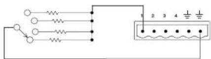
Various types of control hardware can be connected to the Control Input pins, as shown in Figure 14. When properly configured, the DFR22 changes to the appropriate preset in response to the switch. Resistor values for custom switches and the Shure DRS10 are listed in Table 4.
NOTE: The total resistance of the cable run, from the switch to the DFR22, should be less than 100 ohms. Two-conductor, unshielded cable, such as a Belden 8442, is recommended.
Table 4. CUSTOM SWITCH RESISTOR VALUES
| PRESET | RESISTOR VALUE |
| 1 | 97 kΩ – ∞ Ω |
| 2 | 44–60 kΩ |
| 3 | 26–32 kΩ |
| 4 | 17–20 kΩ |
| 5 | 11.3–13.6 kΩ |
| 6 | 7.8–9.3 kΩ |
| 7 | 5.2–6.3 kΩ |
| 8 | 3.3–4.1 kΩ |
| 9 | 1.9–2.5 kΩ |
| 10 | 0.63–1.1 kΩ |
Table 3. BINARY CONTROL PIN ALLOCATION
| Number of Presets | Pin Numbers |
| 2 | 1 |
| 4 | 1 and 2 |
| 8 | 1-3 |
| 16 | 1-4 |
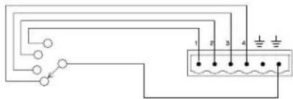
One-to-one Configuration (Each pin represents one preset)
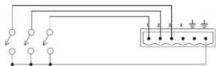
Binary Configuration
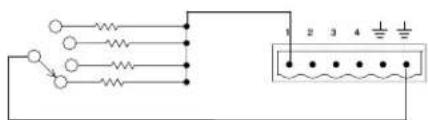
Shure DRS10 or Custom Switch Configuration*
WIRING CONTROL INPUT PINS FOR PRESET CONTROL
Figure 14
Mute Control Connections
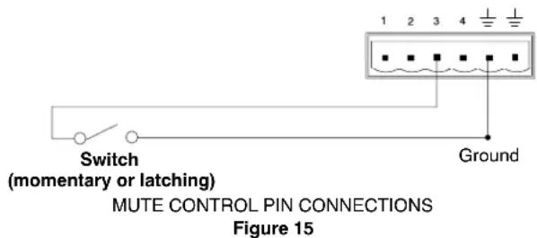
For mute control, use either a latching switch or a momentary switch. The total resistance of the cable run from the switch to the DFR22 should be less than 100 ohms.
Figure 15 shows an example of how to connect either a latching switch or a momentary switch to the Control Input pins to mute an input or an output.
Gain Control Connections
For gain control, use either a potentiometer or two momentary switches (one for gain up and one for gain down). If you want to have multiple sets of gain controls acting on the same inputs or outputs, use momentary switches connected in parallel. Figure 16 shows a typical connection between a potentiometer and the Control Input pins. Figure 17 shows a typical connection between two momentary switches and the Control Input pins.
When using a potentiometer, the total resistance of the cable run should be less than 100 ohms.
When using momentary switches, the total resistance of the cable run should be less than 100 ohms.
NOTE: As supplied, the DFR22 control pins are configured for use with a 10 Kohm audio taper potentiometer. However, you can use the Potentiometer Calibration Wizard in the DFR22 software to configure the DFR22 for use with any 10 Kohm, 20 Kohm, 50 Kohm, or 100 Kohm linear or audio taper potentiometer.
AMX / Crestron Control Connections
You can connect an AMX or Crestron controller to the back panel RS-232 port, using a Phoenix connector, or to the front panel RS-232 port, using a DB-9 connector. In either case, you only need to connect three wires: send, receive, and ground. See page 8 for the pinout of the RS-232 ports.
To access AMX/Crestron control codes for the DFR22, visit the DFR22 web page at http://shure.custhelp.com/app/answers/detail/a_id/2951
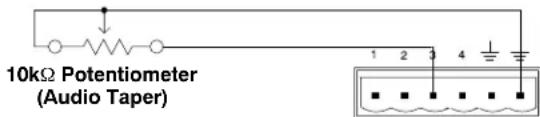
GAIN CONTROL PIN CONNECTIONS USING A POTENTIOMETER
Figure 16
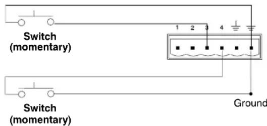
GAIN CONTROL PIN CONNECTIONS USING SWITCHES Figure 17
SPECIFICATIONS
Frequency Response
20 Hz to 20 kHz ±1 dB
Dynamic Range
110 dB minimum, A-weighted, 20 Hz to 20 kHz
Sampling Rate
48 kHz
Digital-to-Analog, Analog-to-Digital Conversion 24 bit
Impedance
Input: 10 kΩ
Output: 120 Ω
Input Clipping Level
+24 dBu minimum
Output Clipping Level
+24 dBu
+12 dBu (with 12 dB pad)
+6 dBu (with 18 dB pad)
Total Harmonic Distortion
< 0.05%, +4 dBu, 20 Hz to 20 kHz
Propagation Delay from Input to Output
<1.5 ms
Polarity
Input to output: non-inverting (inverting optional)
Operating Voltage
100–240 Vac, 50/60 Hz (auto-switching), 1 A, maximum
Maximum Power Drain
45W
Temperature Range
Operating: -7^ to 49^ C (19° to 120° F)
Storage: -29^ to 74^ C ( -20^ to 165^ F)
Dimensions
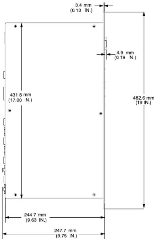
482.6 mm × 247.7 mm × 44.4 mm (19 in. × 9.75 in. × 1.75 in.)
(See Figure 18)
Weight
2.83 kg (6.25 lbs)
Furnished Accessories
Power Cable (DFR22) 95B8389
Power Cable (DFR22E) 95C8247
5-pin DIN Shure Link Cable 95B8676
Hardware Kit 90AY8100
12 Block Connector Terminals, 3-pin
(for audio inputs and outputs)
2 Block Connector Terminals, 10-pin
(for control inputs and outputs)
4 Rackmount Screws and Washers
Optional Accessories
DRS10 Wallplate unit with 10-position rotary switch for preset control
Certifications
Listed by Underwriters Laboratories, Inc.; Certified cUL (Canada). Authorized under Verification provision of FCC Part 15 as a Class B Digital Device.
This Class B digital apparatus complies with Canadian ICES-003.
Conforms to European Union Directives, eligible to bear CE marking. Meets European Union Low Voltage Requirements: Certified to EN 60065. Meets applicable tests and per-
formance criteria in European Standard EN55103 (1996) parts 1 and 2, for residential (E1) and commercial and light industrial (E2) environments.
NOTE: EMC conformance testing is based on the use of supplied and recommended cable types. The use of other cable types may degrade EMC performance.
EMC conformance testing is based on the fact that the computer is used for setup purposes only and disconnected during EMC testing.
Conforms to European Regulation (EC) No. 1275/2008, as amended.
The CE Declaration of Conformity can be obtained from Shure Incorporated or any of its European representatives. For contact information please visit www.shure.com
The CE Declaration of Conformity can be obtained from:
www.shure.com/europe/compliance
Authorized European representative:
Shure Europe GmbH
Headquarters Europe, Middle East & Africa
Department: EMEA Approval
Jakob-Dieffenbacher-Str. 12
75031 Eppingen, Germany
Phone: +49-7262-92 49 0
Fax: +49-7262-92 49 11 4
Email: EMEAsupport@shure.de
Information to User
Changes or modifications not expressly approved by Shure Incorporated could void your authority to operate this equipment.
This equipment has been tested and found to comply with the limits for a Class B digital device, pursuant to Part 15 of the FCC Rules. These limits are designed to provide reasonable protection against harmful interference in a residential installation. This equipment generates, uses and can radiate radio frequency energy and, if not installed and used in accordance with the instructions, may cause harmful interference to radio communications. However, there is no guarantee that interference will not occur in a particular installation. If this equipment does cause harmful interference to radio or television reception, which can be determined by turning the equipment off and on, the user is encouraged to try to correct the interference by one or more of the following measures:
- Reorient or relocate the receiving antenna.
- Increase the separation between the equipment and receiver.
- Connect the equipment into an outlet on a circuit different from that to which the receiver is connected.
- Consult the dealer or an experienced radio/TV technician for help.
LIMITED TWO YEAR WARRANTY
Shure Incorporated ("Shure") hereby warrants that this product will be free from defects in materials and workmanship for a period of two years from the date of purchase. At its option Shure will repair or replace the defective product and promptly return it to you, or refund the purchase price. You should retain proof of purchase to validate the purchase date and return it with any warranty claim.
If you believe this product is defective within the warranty period, carefully repack the unit, insure it, and return it postage prepaid to:
Shure Incorporated
Attention: Service Department
5800 W. Touhy Avenue
Niles, IL 60714-4608 U.S.A.
Outside the United States, return the product to your dealer or Authorized Service Center.
This warranty does not apply in cases of abuse or misuse of the product, use contrary to Shure's instruction, or unauthorized repair. All implied WARRANTIES OF MERCHANTABILITY or FITNESS FOR A PARTICULAR PURPOSE are hereby disclaimed and Shure hereby disclaims liability for incidental, special, or consequential damages resulting from the use or unavailability of this product.
Some states do not allow limitations on how long an implied warranty lasts, or the exclusion or limitation of incidental or consequential damages, so the above limitation may not apply to you. This warranty gives you specific legal rights, and you may have other rights which vary from state to state.
DESCRIPTION
•100–240 V c.a., 50/60 Hz
- 45 W maximum
visiter http://shure.custhelp.com/app/answers/detail/a_id/2951
INSTALLATION DU LOGICIEL
Configuration binaire
Service : Homologation EMA
Jakob-Dieffenbacher-Str. 12
DIMENSIONS DU DFR22
Figure 18
Attention: Service Department
5800 W. Touhy Avenue
Niles, IL 60714-4608 U.S.A.
Attention: Service Department
5800 W. Touhy Avenue
Niles, IL 60714-4608 U.S.A..
Press to Lock / Hold to Clear
Attention: Service Department
5800 W. Touhy Avenue
•100–240 V c.a., 50/60 Hz
- 45 W max.
Computer
Pulsanti Press to Lock / Hold to Clear
CONNETTORI XLR DEL DFR22 (USCITA) CONNETTORI XLR DEL DFR22 (INGRESSO)
Kit hardware 90AY8100
Attention: Service Department
5800 W. Touhy Avenue
Niles, IL 60714-4608 U.S.A.
United States, Canada, Latin
America, Caribbean:
Shure Incorporated
5800 West Touhy Avenue
Niles, IL 60714-4608 USA
Phone: 847-600-2000
Fax: 847-600-1212 (USA)
Fax: 847-600-6446
Email: info@shure.com
Europe, Middle East, Africa:
Shure Europe GmbH
Jakob-Dieffenbacher-Str. 12,
75031 Eppingen, Germany
Phone: 49-7262-92490
Fax: 49-7262-9249114
22/F, 625 King's Road
North Point, Island East
Hong Kong
Phone: 852-2893-4290
Fax: 852-2893-4055
- DFR22
- Audio Processor with Feedback Reduction
- ! IMPORTANT SAFETY INSTRUCTIONS!
- ! CONSIGNES DE SÉCURITÉ IMPORTANTES !
- DFR22 Features
- PACKING LIST
- REQUIREMENTS
- Power Requirements
- Computer Requirements
- SOFTWARE INSTALLATION
- USING THE DFR22 SOFTWARE
- OVERVIEW
- Front Panel
- INPUT/OUTPUT Level Meters:
- Back Panel
- DEFAULT PRESETS
- FRONT PANEL CONTROL FUNCTIONS
- Auto Clear
- Press to Lock / Hold to Clear
- Bypass DFR Filters
- Changing Presets
- Front Panel Lockout
- DFR22 Theory
- Feedback Reduction
- DFR22 Limitations
- RACK MOUNTING THE DFR22
- POWER AND INITIALIZATION
- Power Mains Connections
- Initialization
- AUDIO CONNECTIONS
- Wiring Connectors
- dB and 18 dB Output Pads
- COMPUTER CONNECTIONS
- RS-232 Connections
- Shure Link Network
- DIP Switch Settings for Networked Devices
- CONTROL PIN CONNECTIONS
- Determining Control Pin Allocations
- Preset Control Connections
- Mute Control Connections
- Gain Control Connections
- AMX / Crestron Control Connections
- SPECIFICATIONS
- Frequency Response
- Dynamic Range
- Sampling Rate
- Digital-to-Analog, Analog-to-Digital Conversion 24 bit
- Impedance
- Input Clipping Level
- Output Clipping Level
- Total Harmonic Distortion
- Propagation Delay from Input to Output
- Polarity
- Operating Voltage
- Maximum Power Drain
- Temperature Range
- Dimensions
- Weight
- Furnished Accessories
- Optional Accessories
- Certifications
- Information to User
- LIMITED TWO YEAR WARRANTY
- DESCRIPTION
- INSTALLATION DU LOGICIEL
- Attention: Service Department
- W. Touhy Avenue
- Niles, IL 60714-4608 U.S.A.
- Computer
- Pulsanti Press to Lock / Hold to Clear
Brand : SHURE
Model : DFR22
Category : Processor