
SAT 82 G2 - Loudspeaker LD Systems - Free user manual and instructions
Find the device manual for free SAT 82 G2 LD Systems in PDF.


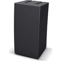
| Product Type | Passive Speaker |
| Brand | LD Systems |
| Model | SAT 82 G2 |
| Dimensions (W x H x D) | 250 x 400 x 230 mm |
| Weight | 7.5 kg |
| Power Handling (RMS) | 200 W |
| Nominal Impedance | 8 ohms |
| Frequency Response | 60 Hz - 20 kHz |
| Sensitivity (1W/1m) | 90 dB |
| Speakers | 1 × 8" woofer, 1 × 1" compression tweeter |
| Connections | 2 × speakON (input/link) |
| Enclosure Material | MDF (Medium Density Fiberboard) |
| Protective Grille | Metal grille |
| Finish | Structured black paint |
| Power | Passive (requires external amplifier) |
| Maintenance and Cleaning | Clean with a soft, dry cloth. Do not use solvents or abrasive products. |
| Safety | Wall mounting mandatory for suspended use. Observe load limits. Keep away from water and heat sources. |
| Spare Parts and Repairability | Spare parts are available through LD Systems after-sales service. Repair by qualified technician recommended. |
| Warranty | 2 years (according to applicable legislation) |
| Intended Use | Small to medium sound reinforcement, fixed or mobile installation |
Frequently Asked Questions - SAT 82 G2 LD Systems
User questions about SAT 82 G2 LD Systems
0 question about this device. Answer the ones you know or ask your own.
Ask a new question about this device
Download the instructions for your Loudspeaker in PDF format for free! Find your manual SAT 82 G2 - LD Systems and take your electronic device back in hand. On this page are published all the documents necessary for the use of your device. SAT 82 G2 by LD Systems.
USER MANUAL SAT 82 G2 LD Systems
natural_image
Four black outdoor audio speakers with textured covers, arranged in ascending size from left to right (no visible text or labels)LDSATG²/ SUB SERIES
PASSIVE INSTALLATION SPEAKER: LDSAT42G2(W) / LDSAT242G2(W) / LDSAT442G2(W)
LDSAT62G2(W) / LDSAT82G2(W) / LDSUB88
ACTIVE INSTALLATION SPEAKER: LDSAT82AG2(W) / LDSAT62AG2(W) / LDSUB88A /
LDSUB10A
EN You've made the right choice!
We have designed this product to operate reliably over many years. LD Systems stands for this with its name and many years of experience as a manufacturer of high-quality audio products. Please read this User's Manual carefully, so that you can begin making optimum use of your LD Systems product quickly.
You can find more information about LD-SYSTEMS at our Internet site WWW.LD-SYSTEMS.COM
- Please read these instructions carefully.
- Keep all information and instructions in a safe place.
- Follow the instructions.
- Observe all safety warnings. Never remove safety warnings or other information from the equipment.
- Use the equipment only in the intended manner and for the intended purpose.
- Use only sufficiently stable and compatible stands and/or mounts (for fixed installations). Make certain that wall mounts are properly installed and secured. Make certain that the equipment is installed securely and cannot fall down.
- During installation, observ e the applicable safety regulations for your country.
- Never install and operate the equipment near radiators, heat registers, ovens or other sources of heat. Make certain that the equipment is always installed so that is cooled sufficiently and cannot overheat.
- Never place sources of ignition, e.g., burning candles, on the equipment.
- Ventilation slits must not be blocked.
- Do not use this equipment in the immediate vicinity of water (does not apply to special outdoor equipment - in this case, observe the special instructions noted below. Do not expose this equipment to flammable materials, fluids or gases. Avoid direct sunlight!
- Make certain that dripping or splashed water cannot enter the equipment. Do not place containers filled with liquids, such as vases or drinking vessels, on the equipment.
- Make certain that objects cannot fall into the device.
- Use this equipment only with the accessories recommended and intended by the manufacturer.
- Do not open or modify this equipment.
- After connecting the equipment, check all cables in order to prevent damage or accidents, e.g., due to tripping hazards.
- During transport, make certain that the equipment cannot fall down and possibly cause property damage and personal injuries.
- If your equipment is no longer functioning properly, if fluids or objects have gotten inside the equipment or if it has been damaged in anot her way, switch it off immediately and unplug it from the mains outlet (if it is a powered device). This equipment may only be repaired by authorized, qualified personnel.
- Clean the equipment using a dry cloth.
- Comply with all applicable disposal laws in your country. During disposal of packaging, please separate plastic and paper/cardboard.
- Plastic bags must be kept out of reach of children.
FOR EQUIPMENT THAT CONNECTS TO THE POWER MAINS
- CAUTION: If the power cord of the device is equipped with an earthing contact, then it must be connected to an outlet with a protective ground. Never deactivate the protective ground of a power cord.
- If the equipment has been exposed to strong fluctuations in temperature (for example, after transport), do not switch it on immediately. Moisture and condensation could damage the equipment. Do not switch on the equipment until it has reached room temperature.
- Before connecting the equipment to the power outlet, first verify that the mains voltage and frequency match the values specified on the equipment. If the equipment has a voltage selection switch, connect the equipment to the power outlet only if the equipment values and the mains power values match. If the included power cord or power adapter does not fit in your wall outlet, contact your electrician.
- Do not step on the power cord. Make certain that the power cable does not become kinked, especially at the mains outlet and/or power adapter and the equipment connector.
- When connecting the equipment, make certain that the power cord or power adapter is always freely accessible. Always disconnect the equipment from the power supply if the equipment is not in use or if you want to clean the equipment. Always unplug the power cord and power adapter from the power outlet at the plug or adapter and not by pulling on the cord. Never touch the power cord and power adapter with wet hands.
- Whenever possible, avoid switching the equipment on and off in quick succession because otherwise this can shorten the useful life of the equipment.
- IMPORTANT INFORMATION: Replace fuses only with fuses of the same type and rating. If a fuse blows repeatedly, please contact an authorised service centre.
- To disconnect the equipment from the power mains completely, unplug the power cord or power adapter from the power outlet.
- If your device is equipped with a Volex power connector, the mating Volex equipment connector must be unlocked before it can be removed. However, this also means that the equipment can slide and fall down if the power cable is pulled, which can lead to personal injuries and/or other damage. For this reason, always be careful when laying cables.
- Unplug the power cord and power adapter from the power outlet if there is a risk of a lightning strike or before extended periods of disuse.

CAUTION: Never remove the cover, because otherwise there may be a risk of electric shock. There are no user serviceable parts inside. Have repairs carried out only by qualified service personnel.

The lightning flash with arrowhead symbol within an equilateral triangle is intended to alert the user to the presence of uninsulated “dangerous voltage” within the product’s enclosure that may be of sufficient magnitude to constitute a risk of electrical shock.
The exclamation mark within an equilateral triangle is intended to alert the user to the presence of important operating and maintenance instructions.
CAUTION – HIGH VOLUME LEVELS WITH AUDIO PRODUCTS!
This equipment is intended for professional use. Therefore, commercial use of this equipment is subject to the respectively applicable national accident prevention rules and regulations. As a manufacturer, Adam Hall is obligated to notify you formally about the existence of potential health risks. Hearing damage due to high volume and prolonged exposure: When in use, this product is capable of producing high sound-pressure levels (SPL) that can lead to irreversible hearing damage in performers, employees, and audience members.
For this reason, avoid prolonged exposure to volumes in excess of 90 dB.

To prevent possible hearing damage, avoid listening at high volume levels over long periods of time. Even exposure to short bursts of loud noise can result in hearing loss. Please keep the volume constantly at a comfortable level.
APPAREILS RELIÉS AU SECTEUR
Up to four SAT42G2(W) or SAT62G2(W) speakers per power amplifier output can be operated in parallel at 4 ohms. The speaker signal is simply looped through to the next speaker via the connector panel on the rear.
SAT242G2(W), SAT442G2(W) and SAT82G2(W)
Up to two SAT42G2(W), SAT442G2(W) or SAT62G2(W) speakers per power amplifier output can be operated in parallel at 4 ohms. The speaker signal is simply looped through to the next speaker via the connector panel on the rear.
SUB88 in conjunction with SAT42G2(W), SAT62G2(W), SAT242G2(W) or SAT82G2(W)
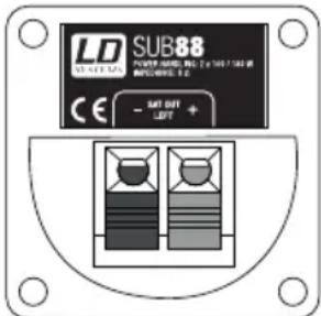
Connect the speaker cables from the power amplifier (Output Left and Right) to the Input Left and Right connectors of the subwoofer. Afterwards, connect the SAT Series speakers to the Output Left and Right connectors of the subwoofer. Up to two SAT42G2(W) or SAT62G2(W) speakers per subwoofer output (Output Left and Right) can be operated in parallel at 4 ohms. One SAT242G2(W), SAT442G2(W) or SAT82G2(W) speaker per subwoofer output (Output Left and Right) can be operated in this configuration at 4 ohms. We recommend using speaker cable with a conductor cross-section of at least 2 × 1.5 mm^2 .
Active Speakers
It is advisable to always turn on active speakers last and turn them off first in order to avoid the switch-on noises caused by connected mixers, etc. If multiple active speakers are connected one after the other in series (SAT62AG2), then they should always be switched on in the order in which they are connected and switched off in reverse order.
Turn the active speakers off before you connect them. They can be connected both via 6.3 mm TRS plugs (balanced three-pole / unbalanced two-pole) as well as balanced three-pole XLR plugs. Once you have connected all of the necessary cables and set the volume (MAIN LEVEL) of the active speaker to minimum, you can switch on the audio source (e.g., mixer). Afterwards you can also switch on the active speakers. Start an audio signal and now turn the MAIN LEVEL knob clockwise until the desired volume is attained. Carry out these steps with all connected active speakers. On the following pages of this user manual, you will find a summary of the connectors, controls, and indicators.
SUB 10A in conjunction with passive SAT Series speakers
Connect the passive SAT Series speakers to the speaker outputs (SPEAKER OUT LEFT / RIGHT) of the SUB10A.
Up to four SAT42G2(W) or SAT62G2(W) speakers per speaker output can be operated in parallel. The speaker signal is simply looped through to the next speaker via the connector panel on the rear of the passive speaker.
Up to two SAT242G2(W) or SAT862G2(W) speakers per speaker output can be operated in parallel. The speaker signal is simply looped through to the next speaker via the connector panel on the rear of the passive speaker.
We recommend using speaker cable with a conductor cross-section of at least 2 x 1.5 mm ^4 .
SUB10A in conjunction with SAT62AG2(W) and SAT82AG2(W) active speakers
Connect the active speakers to the line outputs (LINE DIRECT OUTPUT) of the SUB10A.
Looping Through the signal
With the SAT62AG2(W) and SAT82AG2(W) active speakers, the audio signal can be looped through to additional systems using a three-pole XLR cable. Accordingly, it is not necessary to connect each device to the audio source individually. Please use high-quality XLR cables for this and ensure that they are connected carefully.
SUB88A
To connect the SUB88A active subwoofer to the SAT62AG2 and SAT82AG2(W) active speakers, the subwoofer must be connected as the last speaker in the chain, since it only has one line input.
EN Balanced XLR line output for looping through the input signal.
EN Toggles between continuous operation (ON) and auto mode (AUTO). In the AUTO position, the amplifier of the speaker system switches on automatically as soon as a signal is received. If there is no signal for several minutes, the amplifier switches to standby mode.
EN The LED lights up red if the unit is switched on and is in AUTO mode, but no signal is present. Once a signal is present, the LED changes colours to green. The LED also lights up green if the unit is switched on and is in ON mode.
EN Lights up if the speaker is operating in the clipping range. Brief flashing is not a cause for concern, since the internal audio limiter compensates for over-modulation. Permanent illumination should be avoided by reducing the input level.
EN Terminal posts for speaker cables. Connection of speakers or speaker systems with a total impedance of at least 4 ohms per channel. Connect the positive pole (+) of the speaker cable to the red terminal clamp (+) and the negative pole (-) of the speaker cable to the black terminal clamp (-) of the respective channel. Optionally, speaker cables with banana plugs can also be used.
EN IEC power socket 220V-240V with built-in fuse holder. IMPORTANT INFORMATION: Replace the fuse only with a fuse of the same type and rating. If the fuse blows repeatedly, please contact an authorised service centre.
EN On / off switch. Before switching the active speaker on or off, always adjust the volume to zero (MAIN LEVEL all the way to the left).
EN IEC power socket 220V-240V with built-in fuse holder. IMPORTANT INFORMATION: Replace the fuse only with a fuse of the same type and rating. If the fuse blows repeatedly, please contact an authorised service centre.
EN On / off switch. Before switching the active speaker on or off, always adjust the volume to zero (SUB LEVEL all the way to the left).
EN Variable low-pass filter 70 - 140 Hz. Controls the lower limit frequency of the subwoofer.
EN Lights up when the subwoofer is switched on and properly connected to the power mains.
EN The LED lights up when an audio signal is present at the line input.
EN Lights up if the speaker is operating in the clipping range. Brief flashing is not a cause for concern, since the internal audio limiter compensates for over-modulation. Permanent illumination should be avoided by reducing the input level.
LDSUB88 PASSIVE SUBWOOFER / LDSUB88 SUBWOOFER PASSIV / LDSUB88 CAISSON DE BASSES PASSIF / SUBWOOFER PASIVO LDSUB88 / SUBWOOFER PASYWNY LDSUB88 / SUBWOOFER PASSIVO LDSUB88
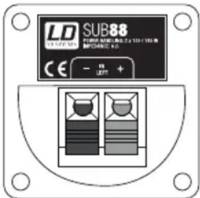
SUB88 IN (IN LEFT shown) / SUB88 IN (abgebildet IN LEFT) / SUB88 IN (sur l'illustration : IN LEFT) / SUB88 IN (en la figura IN LEFT) / SUB88 IN (na ilustracji IN LEFT) / SUB88 IN (nell'immagine IN LEFT)
EN Terminal clamps for speaker cables. Connect the positive pole (OUTPUT LEFT +) of the speaker cable coming from the amplifier to the red terminal clamp (IN LEFT +) and the negative pole (OUTPUT LEFT -) of the speaker cable coming from the amplifier to the black terminal clamp (IN LEFT -) of the subwoofer. Connect the SUB88 IN RIGHT and the amplifier OUTPUT RIGHT in the same manner.
DE Klemmanschlüsse für Lautsprecherkabel. Verbinden Sie den Pluspol (OUTPUT LEFT +) des vom Verstärker kommenden Lautsprecherkabels mit dem roten Klemmanschluss (IN LEFT +) und den Minuspol (OUTPUT LEFT -)
des vom Verstärker kommenden Lautsprecherkabels mit dem schwarzen Klemmanschluss (IN LEFT -) des Subwoofers. Verbinden Sie SUB88 IN RIGHT und Verstärker OUTPUT RIGHT in gleicher Weise.
FR Borniers à pince pour câble haut-parleur Reliez le conducteur positif (OUTPUT LEFT +) du câble haut-parleur provenant de l'amplificateur au bornier rouge (repéré IN LEFT +) et le conducteur négatif (OUTPUT LEFT -) du câble haut-parleur provenant de l'amplificateur au bornier noir (repéré IN LEFT -) du caisson de basses. Reliez ensuite l'entrée IN RIGHT du SUB88 à la sortie OUTPUT RIGHT de l'amplificateur en procédant de la même façon.
ES Bornas de conexión para el cable de altavoz. Conecte el conductor positivo (OUTPUT LEFT +) del cable de altavoz procedente del amplificador al borne rojo (IN LEFT +), y el conductor negativo (OUTPUT LEFT -) del cable de altavoz al borne negro (IN LEFT -) del subwoofer. De igual forma, conecte IN RIGHT del SUB88 y OUTPUT RIGHT del amplificador.
PL Przyłącza zaciskowe do kabla głośnikowego Biegun dodatni (OUTPUT LEFT +) kabla głośnikowego wychodzącego ze wzmacniacza należy podłączyć do czerwonego przyłącza zaciskowego (IN LEFT +), a biegun ujemny (OUTPUT LEFT -) kabla głośnikowego wychodzącego ze wzmacniacza do czarnego przyłącza zaciskowego (IN LEFT -). W taki sam sposób należy połączyć urządzenie SUB88 IN RIGHT i wzmacniacz OUTPUT RIGHT.
IT Attacchi a morsetto per cavo altoparlante. Collegare il polo positivo (OUTPUT LEFT +) del cavo dell'altoparlante proveniente dall'amplificatore all'attacco rosso a morsetto (IN LEFT +) e il polo negativo (OUTPUT LEFT -) del cavo dell'altoparlante proveniente dall'amplificatore all'attacco nero a morsetto (IN LEFT -) del subwoofer. Collegare SUB88 IN RIGHT e amplificatore OUTPUT RIGHT allo stesso modo.
SUB88 SAT OUT (SAT OUT LEFT shown) / (abgebildet SAT OUT LEFT) / SUB88 SAT OUT (sur l'illustration : SAT OUT LEFT) / SUB88 SAT OUT (en la figura SAT OUT LEFT) / SUB88 SAT OUT (na ilustracji SAT OUT LEFT) / SUB88 SAT OUT (nell'immagine SAT OUT LEFT)
7
EN M6 socket screw x 16
DE Inbusschraube M6 x 16
FR Vis M6 x 16
ES Tornillo Allen M6 x 16
PL śruba imbusowa M6 x 16
IT Vite a brugola M6 x 16
8
flowchart
graph TD
    A["Sat Out Left Sat Out Right"] --> B["Substation Box"]
    C["Substation In Left Sub88 In Right"] --> B
    D["Speaker Out Left Speaker Out Right"] --> B
OPTIONAL ACCESSORIES / OPTIONALES ZUBEHÖR / ACCESSOIRES OPTIONNELS / ACCESORIOS OPCIONALES / AKCESORIA OPCJONALNE / ACCESSORI OPZIONALI
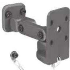
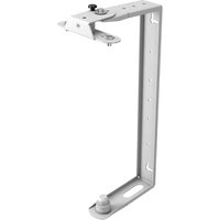
SUWMB10B (black) / (schwarz) / (noir) / (negro) / (czarny) / (nero) SUWMB10W (white) / (weiß) / (blanc) / (blanco) / (biały) / (blanco)
EN Universal speaker wall bracket with safety rope. Four snap-lock joints permit mounting of the speaker in virtually any position. Maximum load: 10 kg
DE Universelle Lautsprecher-Wandhalterung mit Sicherungsseil. 4 gerasterte Gelenke ermöglichen es, den Lautsprecher in nahezu jeder Position zu montieren. Maximale Traglast: 10 kg
FR Fixation murale universelle pour enceinte, avec élingue de sécurité 4 articulations permettent d'orienter l'enceinte dans pratiquement n'importe quelle position. Charge maximale: 10 kg
ES Soporte universal de pared para altavoz con cable de seguridad. Sus 4 articulaciones permiten situar el altavoz en casi cualquier posición. Máxima capacidad de carga: 10 kg
PL Uniwersalny ścienny uchwyt głośnikowy z liną bezpieczeństwa. 4 przeguby z blokadą umożliwiają montaż głośnika w prawie każdej pozycji. Nośność maksymalna: 10 kg
IT Supporto da muro universale per altoparlante con cavo di sicurezza. Quattro giunti articolati consentono di montare l'altoparlante praticamente in qualsiasi posizione. Portata massima: 10 kg
natural_image
Mechanical bracket with mounting holes and a separate terminal component (no text or symbols visible)SPECIFICATIONS / SPEZIFIKATIONEN / CARACTÉRISTIQUES / ESPECIFICACIONES / SPECYFIKACJE / SPECIFICHE
EN
LDSAT42G2(W) LDSAT242G2(W) LDSAT62G2(W) LDSAT82G2(W) LDSAT442G2(W)
| Product type | Installation Speakers | Installation Speakers | Installation Speakers | Installation Speakers | installation speakers |
| Type: passive passive passive passive passive | |||||
| Woofer size: 4" / 101 mm 2 x 4" / 2 x 101 mm 6,5" / 165 mm 8" / 203 mm 4 x 4" / 4 x 101 mm | |||||
| Woofer magnet: ferrite ferrite ferrite ferrite ferrite | |||||
| Woofer brand: custom made custom made custom made custom made custom made | |||||
| HF driver size: 1" / 25 mm 1" / 25 mm 1" / 25 mm 1" / 25 mm 1" / 25 mm | |||||
| HF driver magnet: ferrite ferrite ferrite ferrite ferrite | |||||
| HF driver brand: | custom made custom made custom made custom made custom made custom made | ||||
| Dispersion angle (H x V): | 60 x 60° | 60 x 60° | 60 x 60° | 60 x 60° | 120°x 30° |
| Power output (RMS): | 60 W | 100 W | 80 W | 120 W | 200 W |
| Frequency response: | 75 Hz - 20,000 Hz | 75 Hz - 20,000 Hz | 55 Hz - 20,000 Hz | 50 Hz - 20,000 Hz | 75 Hz - 20,000 Hz |
| Sound-pressure level (1 W/1 m): | 85 dB 88 dB | 89 dB 93 dB | 94 dB | ||
| Max SPL: | 103 dB | 108 dB | 108 dB | 114 dB | 114 dB |
| Impedance: | 16 ohms | 8 ohms | 16 ohms | 8 ohms | 8 ohms |
| Protection: | HF driver | HF driver | HF driver | HF driver | HF driver |
| Speaker inputs: | 1 | 1 | 1 | 1 | 1 |
| Speaker input connections: | Clamp connector | Clamp connector | Clamp connector | Clamp connector | clamp connector |
| Cabinet material: | 12 mm MDF | 12 mm MDF | 12 mm MDF | 15 mm MDF | 12 mm MDF |
| Cabinet surface: | textured coating | textured coating | textured coating | textured coating | textured coating |
| Cabinet colour: | black (LDSAT42G2) / white (LDSAT42G2W) | black (LDSAT242G2) / white (LDSAT242G2W) | black (LDSAT62G2) / white (LDSAT62G2W) | black (LDSAT82G2) / white (LDSAT82G2W) | black (LDSAT442G2) / white (LDSAT442G2W) |
| Cabinet type: | closed | closed | bass reflex | bass reflex | dosed |
| Dimensions (W x H x D): | 140 x 230 x 125 mm | 140 x 378 x 135 mm | 200 x 320 x 200 mm | 274 x 410 x 243 mm | 140 x 670 x 155 mm |
| Weight: | 5 kg / pair | 4.15 kg | 8.2 kg / pair | 7 kg | 8 kg |
| Other features: | Wall bracket included | Wall bracket included | Wall bracket included | Wall bracket included | wall bracket included |
| LDSAT62AG2(W) | LDSAT82AG2(W) | |
| Product type: Installation Speakers | installation speakers | |
| Type: active | active | |
| Woofer size: 6,5" / 165 mm | 8" / 203.2 mm | |
| Woofer magnet: ferrite | ferrite | |
| Woofer brand: custom made | custom made | |
| HF driver size: | 1" / 25 mm 1" / 25 mm | |
| HF driver magnet: | ferrite | ferrite |
| HF driver brand: | custom made | custom made |
| Amplifier: | Class A/B class A/B | |
| Dispersion angle (H x V): | 60 x 60 ° 60° x 60° | |
| Power output (RMS): 50 W | 80 W | |
| Frequency response: 55 Hz - 20,000 Hz | 50 Hz - 20,000 Hz | |
| Max SPL: 108 dB | 114 dB | |
| Protection: | HF driver, overcurrent | overcurrent, HF drivers |
| Controls: | Power switch (on/off), volume control, switchable auto-power mode | volume, power switch (on/off), power mode (on/auto) |
| Indicators: | Power | Power, Limit |
| Line input connectors: | XLR, 6.3 mm TRS (combo) | 6.3 mm TRS, XLR |
| Line output connectors: | XLR | XLR |
| Power supply: transformer transformer | ||
| Operating voltage: | 220 V AC - 240 V AC, 50 - 60 Hz110 V AC - 120 V AC, 50 - 60 Hz (US) | 220 V AC - 240 V AC, 50 - 60 Hz110 V AC - 120 V AC, 50 - 60 Hz (US) |
| Power consumption (max.) | 80 W | 175 W |
| Cabinet material: 12 mm MDF | 12 mm MDF | |
| Cabinet surface: textured coating | textured coating | |
| Cabinet colour: black (LDSAT62AG2) / white (LDSAT62AG2W) | black (LDSAT82AG2) / white (LDSAT82AG2W) | |
| Cabinet type: bass reflex | bass reflex | |
| Dimensions (W x H x D): 200 x 320 x 200 mm | 274 x 410 x 243 mm | |
| Weight: | 5.25 kg | 8.6 kg |
| Other features: | Wall bracket included | wall bracket included |
| LDSUB88 | |
| Product type: Installation Subwoofers | |
| Type: passive | |
| Woofer size: 2 x 8" / 2 x 203 mm | |
| Woofer magnet: ferrite | |
| Woofer brand: custom made | |
| Power output (RMS): 200 (2x100)W | |
| Frequency response: 40 Hz - 120 Hz | |
| Sound-pressure level (1 W/1 m): 92 dB | |
| Max SPL: 115 dB | |
| Impedance: 2 x 8 ohms | |
| Speaker inputs: 2 | |
| Speaker input connections: Clamp connector | |
| Speaker outputs: 2 | |
| Speaker output connections: Clamp connector | |
| Cabinet material: 15 mm MDF | |
| Cabinet surface: textured coating | |
| Cabinet colour: black | |
| Cabinet type: band pass | |
| Dimensions (W x H x D): 600 x 250 x 350 mm | |
| Weight: 13.3 kg | |
| Other features: internal low-pass filter (120 Hz) |
LDSUB10A
| Product type: | |
| Type: active | |
| Woofer size: 10" / 254 mm | |
| Woofer magnet: ferrite | |
| Woofer brand: custom made | |
| Woofer voice coil: | 2" / 50.8 mm |
| Amplifier: Class A/B | |
| Power output (RMS): 360 (3x120)W | |
| Subwoofer frequency range: | 40 Hz - 120 Hz |
| Max. SPL (continuous): | 118 dB |
| Protection: overcurrent, limiter, short-circuit | |
| Input sensitivity: | 0.3 V RMS |
| Controls: Subwoofer volume,power switch (on/off), volume, subwoofer phase reverse | |
| Indicators: Power | |
| Line inputs: 2 | |
| Line input connectors: 6.3 mm TRS, XLR | |
| Line outputs: | 2 x Direct Output |
| Line output connectors: | XLR |
| Speaker outputs: | 2 |
| Speaker output connections: | Terminal posts |
| Power supply: transformer | |
| Operating voltage: | 220 V AC - 240 V AC,50 - 60 Hz110 V AC - 120 V AC,50 - 60 Hz (US) |
| Power consumption (max.): | 600 W |
| Cabinet material: | 15 mm MDF |
| Cabinet surface: | textured coating |
| Cabinet type: | bass reflex |
| Dimensions (W x H x D): | 505 x 345 x 425 mm |
| Weight: | 21 kg |
| Other features: | M20 threaded flange, ergonomic recessed handles, speaker outputs with high-pass filter (170 Hz,-18 dB) |
LDSUB88A
| Product type: Installation Subwoofers | |
| Type: active | |
| Woofer size: 2 x 8" / 2 x 203 mm | |
| Woofer magnet: ferrite | |
| Woofer brand: custom made | |
| Amplifier: Class A/B | |
| Power output (RMS): 150 W | |
| Frequency response: 40 Hz - 120 Hz | |
| Sound-pressure level (1 W/1 m): 92 dB | |
| Max SPL: 115 dB | |
| Protection: overload | |
| Controls: Phase 180°, volume,low-pass filter (70 - 140 Hz) | |
| Indicators: Limit, Signal, Power | |
| Line inputs: 1 | |
| Line input connectors: XLR, 6.3 mm TRS(combo) | |
| Power supply: transformer | |
| Operating voltage: | 220 V AC - 240 V AC,50 - 60 Hz110 V AC – 120 V AC,50 – 60 Hz (US) |
| Power consumption(max.): | 200 W |
| Cabinet material: | 15 mm MDF |
| Cabinet surface: | textured coating |
| Cabinet colour: | black |
| Cabinet type: | band pass |
| Dimensions (W x H x D): | 600 x 250 x 350 mm |
| Weight: | 15 kg |
You can find our current warranty conditions and limitations of liability at: https://cdn-shop.adamhall.com/media/pdf/MANUFACTURERS-DECLARATIONS_LD_SYSTEMS.pdf To request warranty service for a product, please contact Adam Hall GmbH, Adam-Hall-Str. 1, 61267 Neu Anspach / Email: Info@adamhall.com / +49 (0)6081 / 9419-0.

CORRECT DISPOSAL OF THIS PRODUCT
(valid in the European Union and other European countries with a differentiated waste collection system)
This symbol on the product, or on its documents indicates that the device may not be treated as household waste. This is to avoid environmental damage or personal injury due to uncontrolled waste disposal. Please dispose of this product separately from other waste and have it recycled to promote sustainable economic activity. Household users should contact either the retailer where they purchased this product, or their local government office, for details on where and how they can recycle this item in an environmentally friendly manner. Business users should contact their supplier and check the terms and conditions of the purchase contract. This product should not be mixed with other commercial waste for disposal.
FCC STATEMENT
This device complies with Part 15 of the FCC Rules. Operation is subject to the following two conditions:
(1) This device may not cause harmful interference, and
(2) This device must accept any interference received, including interference that may cause undesired operation
CE Compliance
Adam Hall GmbH states that this product meets the following guidelines (where applicable):
R&TTE (1999/5/EC) or RED (2014/53/EU) from June 2017
Low voltage directive (2014/35/EU)
EMV directive (2014/30/EU)
RoHS (2011/65/EU)
The complete declaration of conformity can be found at www.adamhall.com.
Furthermore, you may also direct your enquiry to info@adamhall.com.
(Valid in the European Union and other European countries with waste separation)

- LDSATG²/ SUB SERIES
- EN You've made the right choice!
- FOR EQUIPMENT THAT CONNECTS TO THE POWER MAINS
- CAUTION – HIGH VOLUME LEVELS WITH AUDIO PRODUCTS!
- APPAREILS RELIÉS AU SECTEUR
- SAT242G2(W), SAT442G2(W) and SAT82G2(W)
- SUB88 in conjunction with SAT42G2(W), SAT62G2(W), SAT242G2(W) or SAT82G2(W)
- Active Speakers
- SUB 10A in conjunction with passive SAT Series speakers
- SUB10A in conjunction with SAT62AG2(W) and SAT82AG2(W) active speakers
- Looping Through the signal
- SUB88A
- LDSUB88 PASSIVE SUBWOOFER / LDSUB88 SUBWOOFER PASSIV / LDSUB88 CAISSON DE BASSES PASSIF / SUBWOOFER PASIVO LDSUB88 / SUBWOOFER PASYWNY LDSUB88 / SUBWOOFER PASSIVO LDSUB88
- SUB88 SAT OUT (SAT OUT LEFT shown) / (abgebildet SAT OUT LEFT) / SUB88 SAT OUT (sur l'illustration : SAT OUT LEFT) / SUB88 SAT OUT (en la figura SAT OUT LEFT) / SUB88 SAT OUT (na ilustracji SAT OUT LEFT) / SUB88 SAT OUT (nell'immagine SAT OUT LEFT)
- 7
- 8
- OPTIONAL ACCESSORIES / OPTIONALES ZUBEHÖR / ACCESSOIRES OPTIONNELS / ACCESORIOS OPCIONALES / AKCESORIA OPCJONALNE / ACCESSORI OPZIONALI
- SPECIFICATIONS / SPEZIFIKATIONEN / CARACTÉRISTIQUES / ESPECIFICACIONES / SPECYFIKACJE / SPECIFICHE
- CORRECT DISPOSAL OF THIS PRODUCT
- FCC STATEMENT
- CE Compliance
Brand : LD Systems
Model : SAT 82 G2
Category : Loudspeaker