
Baja Table Tennis Table T8562 - Table tennis table STIGA - Free user manual and instructions
Find the device manual for free Baja Table Tennis Table T8562 STIGA in PDF.

| Product Type | Table Tennis Table |
| Brand | Stiga |
| Model | Baja Table Tennis Table T8562 |
| Playing Surface Material | Aluminum |
| Table Dimensions (Playing Position) | 108 x 60 x 30 inches (standard regulation size) |
| Table Weight | Approximately 200 lbs (90 kg) |
| Warranty | 3-year limited warranty against defects in material and workmanship |
| Assembly Required | Yes, at least 2 adults needed; tools required: Phillips screwdriver, adjustable wrenches, rubber hammer |
| Safety Warnings | Do not sit, stand, lean, walk, or jump on the table; keep out of reach of children during opening/closing; store in protected area to avoid wind damage |
| Net System | Pivoting net and post set with height adjustment (regulation net height: 6 inches from surface) |
| Care Instructions | Clean with soft damp cloth only; do not use chemicals or abrasives; lubricate moving parts periodically with light oil (e.g., WD-40) |
| Storage | Fold and store in dry area; use leg levelers on uneven floors |
| Country of Origin | Not specified in manual (likely China) |
| Item Number | 2L-5056-01 |
Frequently Asked Questions - Baja Table Tennis Table T8562 STIGA
User questions about Baja Table Tennis Table T8562 STIGA
0 question about this device. Answer the ones you know or ask your own.
Ask a new question about this device
Download the instructions for your Table tennis table in PDF format for free! Find your manual Baja Table Tennis Table T8562 - STIGA and take your electronic device back in hand. On this page are published all the documents necessary for the use of your device. Baja Table Tennis Table T8562 by STIGA.
USER MANUAL Baja Table Tennis Table T8562 STIGA
- Read this manual carefully before starting assembly. Read each step completely before beginning each step.
- Some smaller parts may be shipped inside larger parts. Check inside all parts and cartons before assembling or ordering parts.
- Do not tighten hardware until instructed to do so. If hardware is tighten too soon, mounting holes may not align and parts may not easily fit together. Leave locknuts slightly loose until you are instructed to tighten them.
- Tools required for assembly: Phillips Screwdriver, Adjustable Wrenches, Rubber Hammer.
- To make assembly as easy as possible, place all parts of the table in a cleared area and remove the packaging material. Do not dispose of the packing material until assembly is completed. For help in identifying parts, use the Parts List, Hardware Identification and the Exploded Drawings.
- An electric screwdriver is helpful in assembly. However, please set at low torque and use caution because you could overtighten the hardware and strip the screws.
- Save this instruction manual and your proof of purchase (receipt) in the event that the manufacturer has to be contacted for replacement parts.
Please Do Not Return This Product To The Store!
Contact Escalade®Sports customer service department at:
Phone: 1-866-873-3528 Toll-Free!
Fax: 1-866-873-3533 Toll-Free!
E-mail: tabletennis@escaladesports.com
Mailing Address(correspondence only):
Escalade Sports
PO box 889
Evansville, IN 47706
Please visit our World Wide Web site at: www.escaladesports.com
ON-LINE TROUBLE SHOOTING
TECHNICAL ASSISTANCE
ON-LINE PARTS REQUESTS
FREQUENTLY ASKED
QUESTIONS
ADDITIONAL ESCALADE SPORTS PRODUCT INFORMATION
ESCALADE®
SPORTS
2L-5056-01
THREE YEAR LIMITED WARRANTY
This consumer warranty extends to the original consumer purchase of any ESCALADE SPORTS Product (hereinafter referred as the "Product").
WARRANTY DURATION: This Product is warranted to the original consumer purchase of a period of three (3) years from the original purchase.
WARRANTY COVERAGE: ESCALADE SPORTS warrants to the original Consumer Purchaser that any Product of its manufacture is free from defects in material and workmanship when used for the intended purpose under normal use and conditions. THIS WARRANTY IS VOID IF THE PRODUCT HAS BEEN DAMAGED BY ACCIDENT, UNREASONABLE USE, NEGLIGENCE, IMPROPER SERVICE, FAILURE TO FOLLOW INSTRUCTIONS PROVIDED WITH THE PRODUCT OR OTHER CAUSES NOT ARISING OUT OF DEFECTS IN MATERIAL AND WORKMANSHIP.
WARRANTY PERFORMANCE: During the above three (3) year warranty period, ESCALADE SPORTS shall repair or replace with a comparable model, and/or Product, or component thereof, for any product which may prove defective under normal use and proper care, and which our examination shall disclose to our satisfaction to be thus defective, please contact our Warranty Dept.
1-866-873-3528 / Warranty Dept.
Or Write us at:
Escalade® Sports, Inc. - P.O. Box 889, Evansville, IN 47706 - Attn: Warranty Dept.
Or E-mail us at:
tabletennis@escaladesports.com
Other than shipping requirements no charge will be made for such repair or replacement of in-warranty Products. ESCALADE® SPORTS strongly recommends that the Product is insured for value prior to mailing.
WARRANTY DISCLAIMERS: ANY IMPLIED WARRANTIES ARISING OUT OF THIS SALE, INCLUDING BUT NOT LIMITED TO THE IMPLIED WARRANTIES OF MERCHANTABILITY AND FITNESS FOR A PARTICULAR PURPOSE, ARE LIMITED IN DURATION TO THE ABOVE THREE (3) YEAR WARRANTY PERIOD. ESCALADE® SPORTS SHALL NOT BE LIABLE FOR LOSS OF USE OF THE PRODUCT OR OTHER CONSEQUENTIAL OR INCIDENTAL COSTS, EXPENSES OR DAMAGES INCURRED BY THE CONSUMER OF ANY OTHER USE.
Some states do not allow the exclusion or limitation of implied warranties or consequential or incidental damages, so the above limitations or exclusions may not apply to you.
LEGAL REMEDIES: This warranty gives you specific legal rights and you may also have other rights which may vary from state to state.
CAUTION
THIS IS A TABLE TENNIS TABLE. DO NOT SIT, STAND, LEAN, WALK OR JUMP ON TABLE! FAILURE TO COMPLY WITH THIS CAUTION COULD RESULT IN PERSONAL INJURY AND/OR PROPERTY DAMA GE!
UNLEVEL FLOORS
If table does not seem level, it is probably because floor is not level. Move table several inches (set table in playing position) in different directions to find the best location for the table. If the floor is extremely unlevel, table may not play or operate properly. If table is high in the center, adjust levelers on the outer legs
CARE AND MAINTENANCE
You have purchased a quality product that will give you years of enjoyment. By following these simple maintenance steps you will add to the life of your new table. The top (playing surface) of your table is of aluminum construction. It can be affected by atmospheric conditions, meaning both temperature and humidity. This may cause a slight sag or distortion as top expands or contracts. This is normal and should not cause concern as it does not detract from the play or utility value of the table.
STORAGEOF YOUR TABLE
Wind gusts can blow over or unexpectedly open the table; Store in protected area. When your table is not in use, it should be folded up in a dry area.
CLEANING YOURTABLE
To clean your table use a soft damp NOTWET cloth only. To prevent damage to your table's playing surface DO NOT use any chemicals, abrasive, or cleaning products on your table's playing surface.
IMPORTANT: Periodically, lubricate all moving parts, including pivot points, to assure smooth opening and closing. A light lubricant such as WD-40 is recommended.
HARDWARE IDENTIFICATION
20
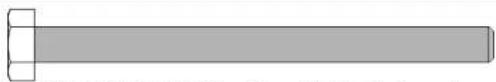
natural_image
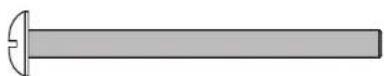
Simple line drawing of a cylindrical object with a square end and rounded top (no text or symbols)1/4-20 X 3 1/4 Hex Head Bolt (4 pieces)
21
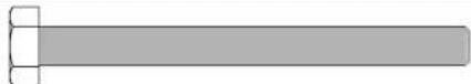
1/4-20 X 2 3/4 Hex Head Bolt (4 pieces)
12
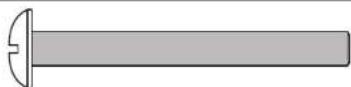
1/4-20 X 2 1/4 Phillips Pan Head Screw (4 pieces)
10
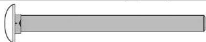
1/4-20 X 2 3/4 Carriage Bolt (4 pieces)
15

8 X 1/2" Phillips Pan Head Screws (12 pieces)
26
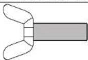
10-24 X 3/4 Thumb Screw (4 pieces)
17
10-24 X 2 1/2 Phillips Pan Head Screw (4 pieces)
37

10 Flat Washer (12 pieces)
24
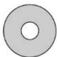
3/4 OD X 1/4 ID Plastic Washer (16 pieces)
19

10-24 Locknut (4 pieces)
27

M12 Hex nut (4 pieces)
14

1/4-20 Nylon locknut (16 pieces)
11


1/2 OD X .281 ID X 3/4 Long Plastic Spacer (12 pieces)
NOTE: If casters came pre-assembled on Caster Beam (#8), skip to Step 2.
- Slide a Caster Wheel with Lock (#13) into Caster Beam as shown in FIGURE 1. On the other end of the Caster Beam attach a Caster Wheel without Lock (#9). Make sure you have one Caster Wheel with lock and a Caster Wheel without lock for each Caster Beam. Repeat this step to attach the Casters to the second Caster Beam.

WARNING:
READ AND FOLLOW ALL ASSEMBLY, OPERATING, AND SAFETY INSTRUCTIONS CAREFULLY. AT LEAST TWO (2) ADULTS ARE NEEDED TO PUT THIS TABLE TOGETHER!
Parts Needed:
2 pcs - #8 Caster Beam
2 pcs - #9 Caster without lock
2 pcs - #13 Caster with lock
with lock
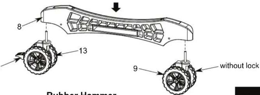
Figure 1
Rubber Hammer
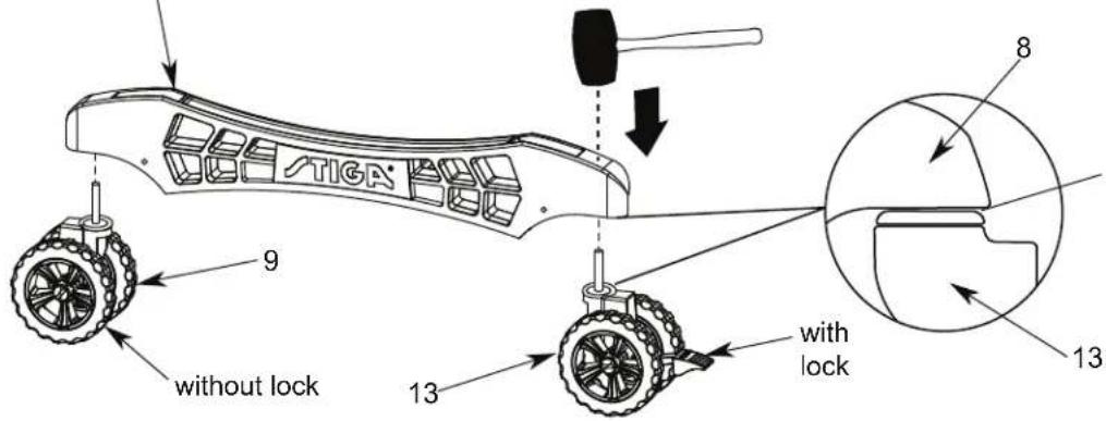
NOTE:
Make sure the Caster
Stem is completely installed
into Caster Beam as shown.
- Attach Cross Tube (#7) to Caster Beam Assemblies (#8) using four Thumb Screws (#26) as shown in FIGURE 2.
Part Needed:
1 pc - #7 Cross Tube
Hardware Needed:
4 pcs - #26 Thumb Screw
NOTE: Assemble with threaded insert facing down.
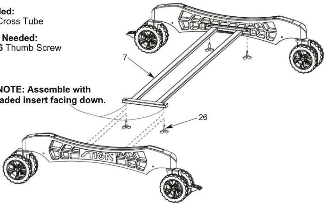
Figure 2
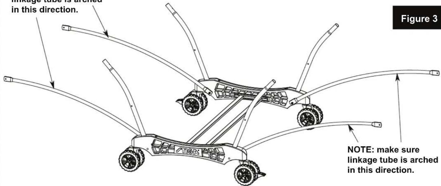
- Attach four Strut Tubes (#4) and four Linkage Tubes (#25) to Caster Beam Assembly using four Carriage Bolts (#10), four Spacers (#11) and four Locknuts (#14) as shown in FIGURE 3.
Snug, but do not overtighten the #14 Locknuts as this is a pivot point.

WARNING:
READ AND FOLLOW ALL ASSEMBLY, OPERATING, AND SAFETY INSTRUCTIONS CAREFULLY. AT LEAST TWO (2) ADULTS ARE NEEDED TO PUT THIS TABLE TOGETHER!
NOTE: make sure linkage and Strut tube are turned as shown.
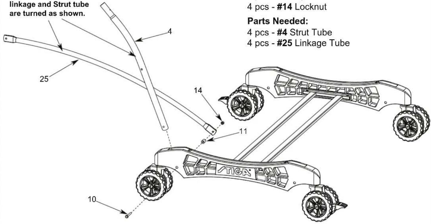
Hardware Needed:
4 pcs - #10 Carriage Bolt
4 pcs - #11 Spacer
4 pcs - #14 Locknut
Parts Needed:
4 pcs - #4 Strut Tube
4 pcs - #25 Linkage Tube
NOTE: make sure linkage tube is arched in this direction.
- A) Attach two Square Legs (#1) between Leg Mounting Brackets (#23) and Leg Mounting Bracket & Brace Assemblies (#6) using two Hex Head Bolts (#21), four Plastic Flat Washers (#24) and two Locknuts (#14) as shown in FIGURE 4 & DETAIL A. Attach middle holes of two Square Legs (#1) to Leg Mounting Bracket & Brace Assemblies (#6) using two Phillips Rd. Hd. Bolts (#17), two Flat Washers (#37) and two Locknuts (#19) as shown in FIGURE 4 & DETAIL A.
B) Install one Hex Nut (#27) to each Leg Leveler (#28). Then install Leg Levelers to Square Legs as shown in FIGURE 4.
Repeat for other Table Top.
Hardware Needed:
2 pcs - #14 Locknut
2 pcs - #17 Phillips Rd. Hd. Bolt
2 pcs - #19 Locknut
2 pcs - #21 Hex Head Bolt
4 pcs - #24 Flat Plastic Washer
2 pcs - #27 Hex Nut
2 pcs - #37 Flat Washer
Parts Needed:
2 pcs - #1 Square Leg-Silver
1 pc - #2 Aluminum Top Assembly
2 pcs - #28 Leg Leveler
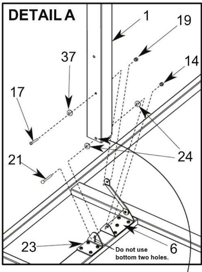
NOTE: Hole is not on center and must be assembled as shown with offset hole toward middle of table.
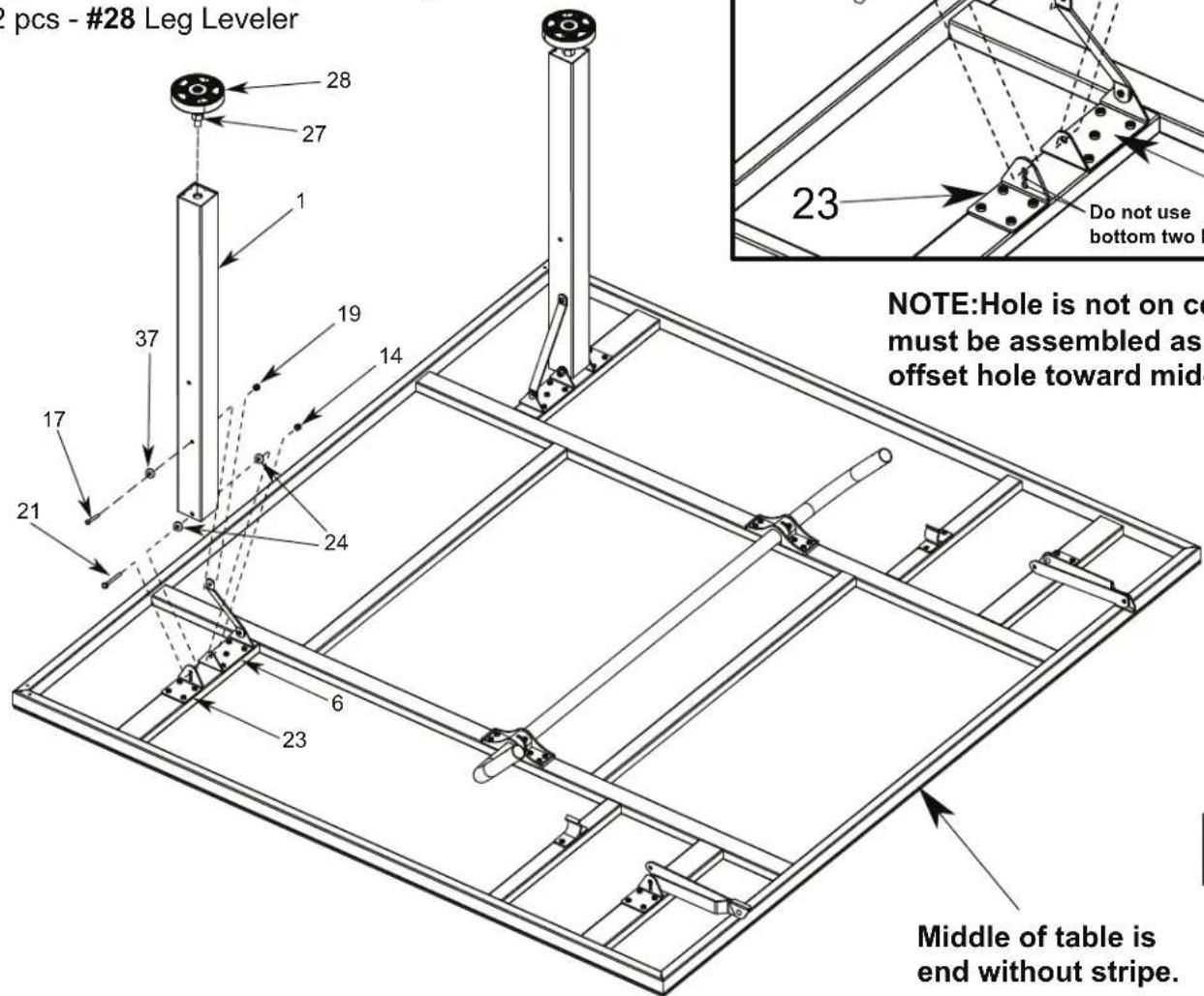
Figure 4

WARNING:
AT LEAST TWO (2) ADULTS ARE NEEDED TO COMPLETE THE REST OF THIS ASSEMBLY! WHEN ASSEMBLING TOPS TO BASE, HANDLE TOP ASSEMBLIES BY GRASPING ONLY THE TOPS THEMSELVES. DO NOT GRASP METAL LEGS, U-SUPPORT, LINKAGE, OR HINGES. THESE PARTS CAN MOVE AND COULD PINCH FINGERS OR HANDS CAUSING SERIOUS INJURY! ASSEMBLE AS SHOWN WITH LEGS FULLY CLOSED AND TOPS IN A VERTICAL POSITION. DO NOT OPEN LEGS AND TRY TO ASSEMBLE. TABLE TOPS ARE HEAVY - DO NO T ATTEMPT TO ASSEMBLE ALONE!
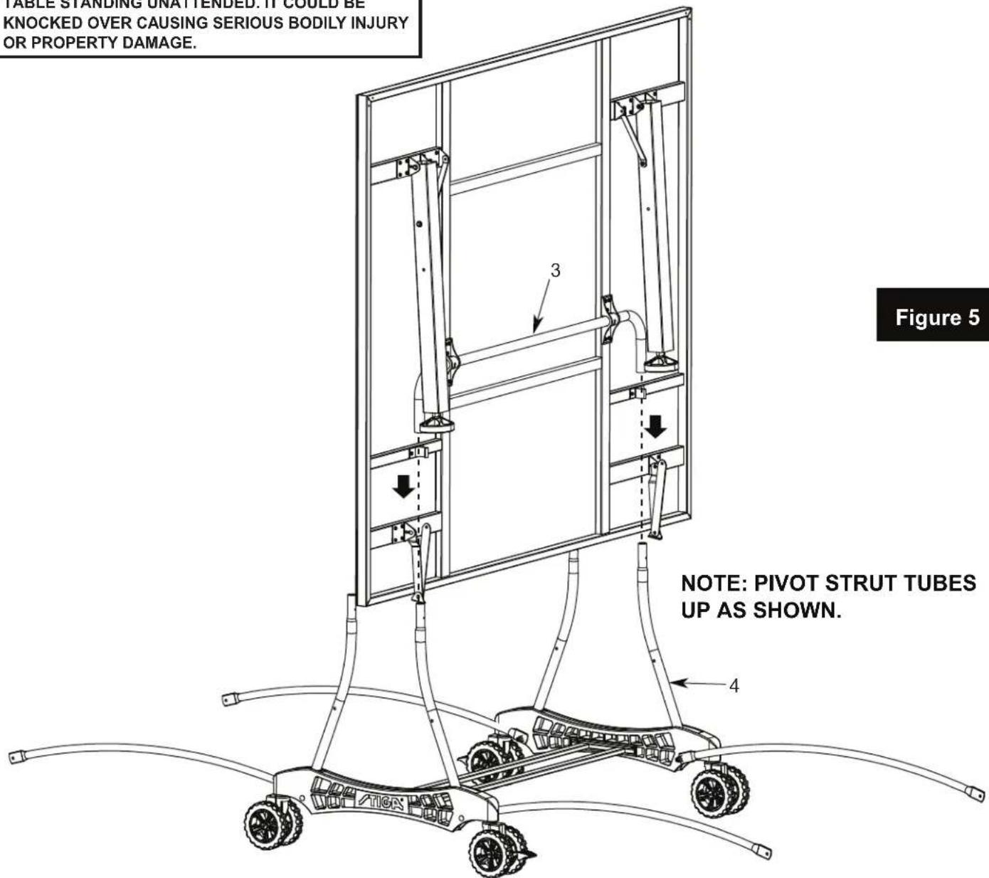
- Attach table top to base assembly. Pivot Strut Tubes (#4) up and then with at least one adult on each side of table top, lift top and align ends of U-support Tube (#3) with tops of strut tubes on caster beams as shown in FIGURE 5. Slide tubes together.
Repeat for other Table Top.

WARNING:
DO NOT OPEN THE TABLE TO PLAYING POSITION UNTIL BOTH TOPS ARE INSTALLED! DO NOT LEAVE TABLE STANDING UNATTENDED. IT COULD BE KNOCKED OVER CAUSING SERIOUS BODILY INJURY OR PROPERTY DAMAGE.
- A) Attach U-Support (#3) and Strut Tubes (#4) using two Phillips Rd. Hd. Screws (#15) as shown in FIGURE 6.
Note: If hinge (#5) is positioned as shown in DETAIL B, you will have to rotate the hinge to the position shown in Detail C. DO NOT unscrew the hinge, you can rotate the hinge without unscrewing it from the table. If you want to see a video on how to position Hinge (#5) go to: http://www.escaladesports.com/customer-service/videos.html
B) Attach Long Hinge & Mounting Bracket Assemblies (#5) to Strut Tubes (#4) using two Bolts (#12), two Spacers (#11), two Flat Plastic Washers (#24) and two Locknuts (#14) as shown in FIGURE 6 & DETAIL C. Tighten Nuts snug, but DO NOT OVERTIGHTEN, hinges must pivot. CAUTION: Hinges must be positioned exactly as shown or table will not operate correctly and could be damaged. DO NOT take Hinges off.
C) Attach Linkage Tubes (#25) to Square Legs (#1) using two Hex Head Bolts (#20), two Flat Plastic Washers (#24), two Spacers (#11) and two Locknuts (#14) as shown in FIGURE 6.
D) Attach two Corner Protectors (#29) to Top Assembly using four Screws (#15) with four Washers (#37) as shown in FIGURE 6.
Repeat for other Table Top.
Hardware Needed:
4 pcs - #11 Spacer
2 pcs - #12 Phillips Rd. Hd. Bolt
4 pcs - #24 Flat Plastic Washer
4 pcs - #14 LockNut
6 pcs - #15 Phillips Rd. Hd. Screw
4 pcs - #37 Washer
2 pcs - #20 Hex head Bolt
ATTENTION: If hinge is positioned as shown below (DETAIL B), rotate the hinge as shown in DETAIL C. Do not take hinge off.
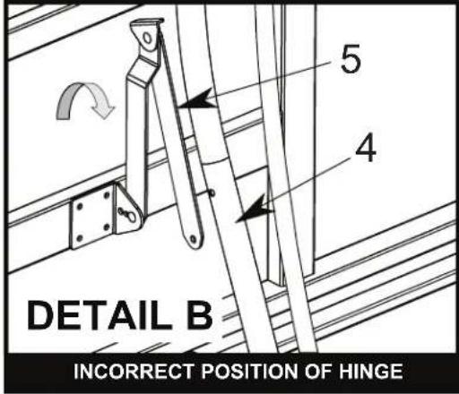
CAUTION: Position hinges exactly as shown in DETAIL C or table will not operate correctly and could be damaged.
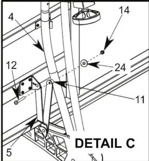
CORRECT POSITION OF HINGE In the correct position Hinge (#5) will look like a "V" when attached to Strut Tube (#4).
Part Needed:
2 pcs - #29 Corner Protector

WARNING:
DO NOT OPEN THE TABLE TO PLAYING POSITION UNTIL BOTH TOPS ARE INSTALLED! DO NOT LEAVE TABLE STANDING UN ATTENDED. IT COULD BE KNOCKED OVER CAUSING SERIOUS BODILY INJURY OR PROPERTY DAMAGE.
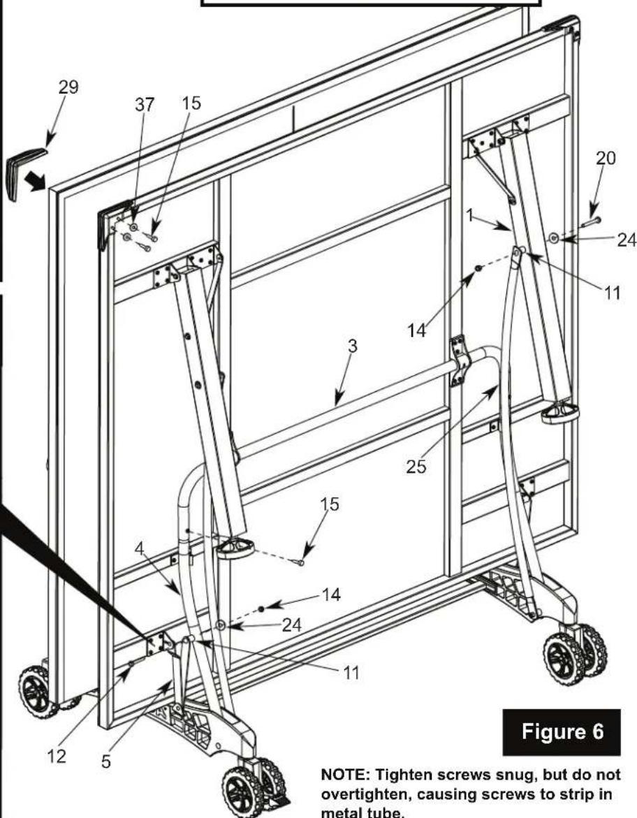
NOTE: Tighten screws snug, but do not overtighten, causing screws to strip in metal tube.
OPENING AND CLOSING INSTRUCTIONS
natural_image
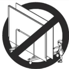
Symbolic illustration of a person standing under a diagonal line crossed over a platform, enclosed in a circle (no text or symbols)WARNING:
WIND GUSTS CAN BLOW OVER OR UNEXPECTEDLY OPEN THE TABLE: STORE IN PROTECTED AREA. EXERCISE CAUTION IN OPENING/CLOSING TABLE. SMALL CHILDREN, OR CHILDREN NOT PROPERLY INSTRUCTED IN ITS USE, MUST NOT BE ALLOWED TO OPEN/CLOSE TABLE. IMPROPER HANDLING AND MISUSE CAN RESULT IN SERIOUS INJURY OR DAMAGE. DO NOT CLIMB, STAND, OR JUMP ON TABLE.
TO OPEN:
- Hold center of top edge. Gently pull outward to midway position. Continue to pull until disengaged from plastic clips and legs rest on the floor as shown in Figure 7A and 7B. Do not leave table partially opened at midway position.
- Lower second top as described in step 1.
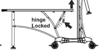
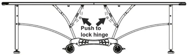
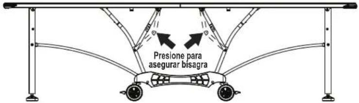
- Lock all four center hinges. See Figure 8.
TO CLOSE:
- Unlock all four center hinges. See Figure 8.
- Lift one table half to midpoint until the plastic clips are engaged. Then continue lifting until closed.
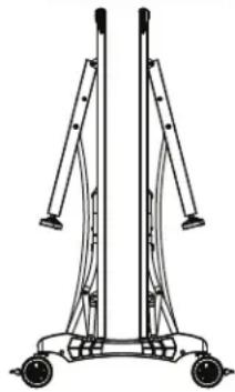
- Raise other table half in the same manner. See Figure 9.
PLAYBACK POSITION
Figure 7A
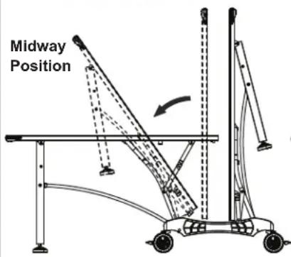
Figure 7B
To lock hinge push up on the table and push hinge as shown in Figure 7B.
Plastic Clip
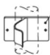
Figure 8
PLAYING POSITION
STORAGE POSITION
natural_image
Technical line drawing of a mechanical support structure with wheels and vertical supports (no text or symbols)Figure 9
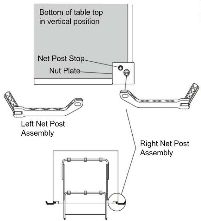
Net System Description
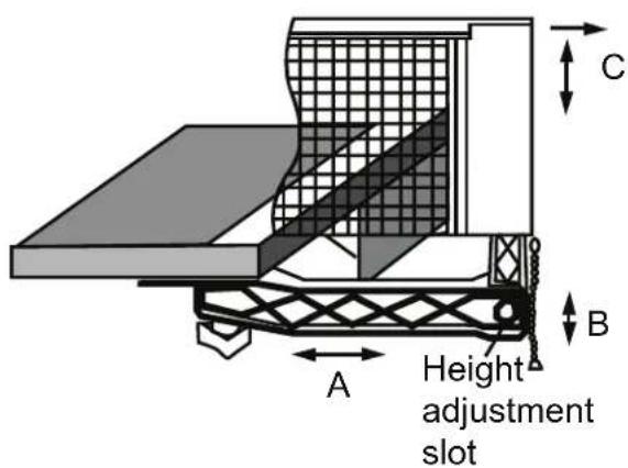
2. Adjustments
A - Adjust overall net tension by slightly loosening the knob and moving net post assembly. Moderately tighten knob. Net post assembly should be kept square with the table by the net post stop (See Net System Description).
B - Adjust tension of cord with bead chain on each side. Assure that chain is fully seated in catch.
C - Position top of net to a regulation height of 6" from the table surface by firmly gripping the vertical net post within height adjustment slot.
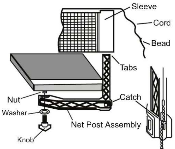
1. Net Post Assembly
Attach plastic net post as shown with washer and knob. Note: there is a left and right net post assembly (See Net System Description). Post assembly should rest flat against nut plate. Slide the net sleeve over the vertical post while the net post assembly is folded in toward the side of the table top. Fold the net post assembly out against the net post stop into the post and secure bead chain in catch.
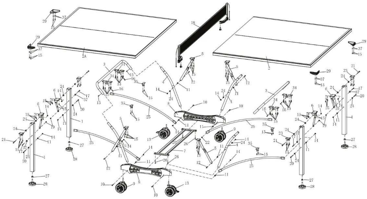
Replacement Parts List for Model Number T8562
2L-5056-01
| Key# | Part# | Description | Qty. |
| 1 | 1A-4121-01 | 2" Square Leg - Silver | 4 |
| 2 | 4A-7909-00 | Aluminum Top Assembly - No Net Mounting Plates | 1 |
| 2A | 4A-7909-10 | Aluminum Top Assembly - With Net Mounting Plates | 1 |
| 3 | 8S-6871-01 | U-Support - Silver | 2 |
| 4 | 8S-4583-01 | Strut Tube - Silver | 4 |
| 5 | 4A-5577-00 | Center Hinge & Mounting Bracket Assembly | 4 |
| 6 | 4A-5578-00 | Leg Mounting Bracket & Brace Assembly | 4 |
| 7 | 4A-5430-00 | Cross Tube Assembly | 1 |
| 8 | 3M-8909-10 | Plastic Caster Beam - Screened "Stiga" | 2 |
| 3M-8909-15 | Plastic Caster Beam Assembly with caster | ||
| 9 | 2Q-4021-00 | 5" Double Wheel Caster - No Lock | 2 |
| 10 | 1B-4148-00 | 1/4-20 X 2 3/4 Carriage Bolt | 4 |
| 11 | 7B-6256-99 | 3/4" Long X .281 I.D. Spacer | 12 |
| 12 | 1B-4150-00 | 1/4-20 X 2 1/4 Phillips Pan Hd. Screw | 4 |
| 13 | 2Q-4022-00 | 5" Double Wheel Caster - With Lock | 2 |
| 14 | 2B-4047-98 | 1/4-20 Nylon Insert Lock Nut | 16 |
| 15 | 1B-7059-00 | #8 X1/2" Phillips Pan Hd. SMS | 12 |
| 16 | 1B-4089-00 | #8-32 X 1 1/4 SMS | 4 |
| 17 | 1B-4151-00 | #10-24 X 2 1/2 Phillips Pan Hd. Screw | 4 |
| 18 | 5A-4243-00 | Pivoting Net & Post Set | 1 |
| 19 | WN-1007-99 | #10-24 Nylon Locknut | 4 |
| 20 | 1B-6477-00 | 1/4-20 X 3 1/4 Hex Hd. Bolt | 4 |
| 21 | 1B-4135-00 | 1/4-20 X 2 3/4 Hex Hd. Bolt | 4 |
| 22 | NOT USED | ||
| 23 | 2S-4684-01 | Mounting Bracket | 4 |
| 24 | 2B-6087-00 | 1/4 Plastic Washer | 16 |
| 25 | 8S-6878-01 | Linkage Tube - Silver | 4 |
| 26 | 1B-4129-00 | #10-24 X 3/4 Thumb Screw | 4 |
| 27 | 2B-6284-00 | M12 Hex Nut | 4 |
| 28 | 2Q-6467-00 | Leg Leveler - M12 Threads | 4 |
| 29 | 3M-4163-10 | Corner Protector | 4 |
| 30 | NOT USED | ||
| 31 | NOT USED | ||
| 32 | NOT USED | ||
| 33 | NOT USED | ||
| 34 | 3M-8921-00 | 1" Molded Tube Bracket | 4 |
| 35 | 3M-6273-00 | 1" Plastic Clip | 4 |
| 36 | 2L-5056-01 | This Owner's Manual | 1 |
| 37 | 2N-0214-99 | #10 Washer | 12 |
MANUAL DEL USUARIO
Escalade® Sports, Inc. - P.O. Box 889, Evansville, IN 47706 - Attn: Warranty Dept.
natural_image
Symbolic illustration of a person standing under a diagonal line with a platform, no text or symbols present.
ADVERTENCIA!
natural_image
Line drawing of a mechanical device with two vertical supports and wheels (no text or symbols)Figura 9
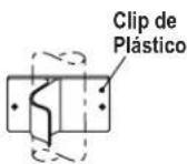
Figura 8
POSICION DE JUEGO
DESCRIPCION DEL SISTEMA DE RED
2. Ajustes
- Please Do Not Return This Product To The Store!
- THREE YEAR LIMITED WARRANTY
- CAUTION
- UNLEVEL FLOORS
- CARE AND MAINTENANCE
- STORAGEOF YOUR TABLE
- CLEANING YOURTABLE
- HARDWARE IDENTIFICATION
- X 1/2" Phillips Pan Head Screws (12 pieces)
- 10-24 X 3/4 Thumb Screw (4 pieces)
- 10-24 X 2 1/2 Phillips Pan Head Screw (4 pieces)
- Flat Washer (12 pieces)
- 10-24 Locknut (4 pieces)
- NOTE: If casters came pre-assembled on Caster Beam (#8), skip to Step 2.
- WARNING:
- Parts Needed:
- Part Needed:
- Hardware Needed:
- Repeat for other Table Top.
- OPENING AND CLOSING INSTRUCTIONS
- TO OPEN:
- TO CLOSE:
- PLAYBACK POSITION
- Net System Description
- Adjustments
- Net Post Assembly
- MANUAL DEL USUARIO
- ADVERTENCIA!
- DESCRIPCION DEL SISTEMA DE RED
- Ajustes
Brand : STIGA
Model : Baja Table Tennis Table T8562
Category : Table tennis table