
BD 5500 - Generator BLACK & DECKER - Free user manual and instructions
Find the device manual for free BD 5500 BLACK & DECKER in PDF.


| Product Type | Portable Generator |
| Model | BD 5500 |
| Brand | Black & Decker |
| Generator Type | Synchronous |
| Rated Voltage (AC) | 230 V a.c. / 400 V a.c. (3-phase) |
| Rated Voltage (DC) | 12 V d.c. |
| Continuous Rated Power (S1) | 3.6 kW |
| Maximum Power (S2, 2 min) | 5.5 kW |
| Frequency | 50 Hz |
| Power Factor | Cos φ = 1 |
| Performance Class | G1 |
| Engine Model | PD188F |
| Engine Type | Single-cylinder, forced air-cooled, 4-stroke OHV |
| Displacement | 389 cm³ |
| Fuel Tank Capacity | 28 L |
| Engine Oil Capacity | ~1.1 L (15W40 / 5W30 below 0°C) |
| Spark Plug | LG F6TC |
| Weight | 91 kg |
| Ingress Protection | IP23M |
| Guaranteed Sound Power Level | 97 dB(A) |
| Maximum Ambient Temperature | 40°C |
| Maximum Altitude | 1000 m above sea level |
| Safety Features | Low oil shutdown, overload circuit breaker, earth connection |
| Recommended Maintenance | Check oil before each use; change oil every 50 h; clean air filter every 50 h; inspect spark plug every 50 h |
Frequently Asked Questions - BD 5500 BLACK & DECKER
User questions about BD 5500 BLACK & DECKER
0 question about this device. Answer the ones you know or ask your own.
Ask a new question about this device
Download the instructions for your Generator in PDF format for free! Find your manual BD 5500 - BLACK & DECKER and take your electronic device back in hand. On this page are published all the documents necessary for the use of your device. BD 5500 by BLACK & DECKER.
USER MANUAL BD 5500 BLACK & DECKER
natural_image
Black and Decker portable electricity generator with visible branding and wheels (no text-heavy elements)GB
Original instructions Generator
D
Black & Decker and the Black & Decker logo are REGISTERED trademarks of The Black & Decker Corporation.
Used under license by:
natural_image
Close-up of hands installing or adjusting a component with a tool, no visible text or symbols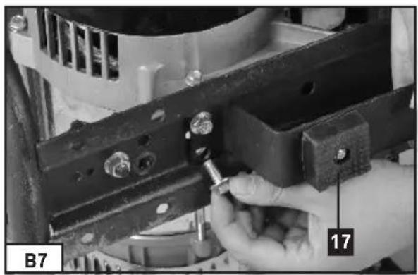
natural_image
Close-up of a hand using a screwdriver to adjust or install a mechanical component (no visible text or symbols)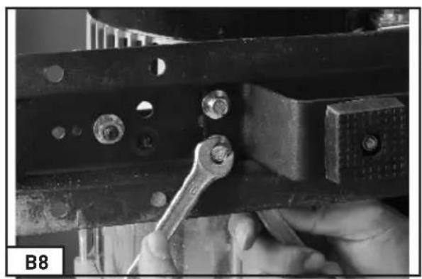
natural_image
Close-up of a hand using a wrench to adjust or install a metal bracket with bolts (no visible text or symbols)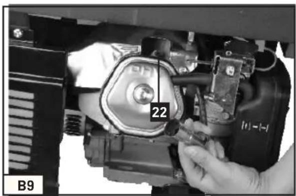
natural_image
Close-up of hands installing or adjusting a mechanical component with a numbered label (22), no readable text or symbols present.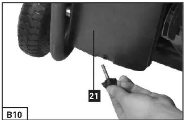
natural_image
Close-up of a hand cleaning the rear wheel of a vehicle (no visible text or symbols)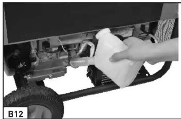
natural_image
Close-up of a hand pouring liquid into a vehicle chassis (no visible text or symbols)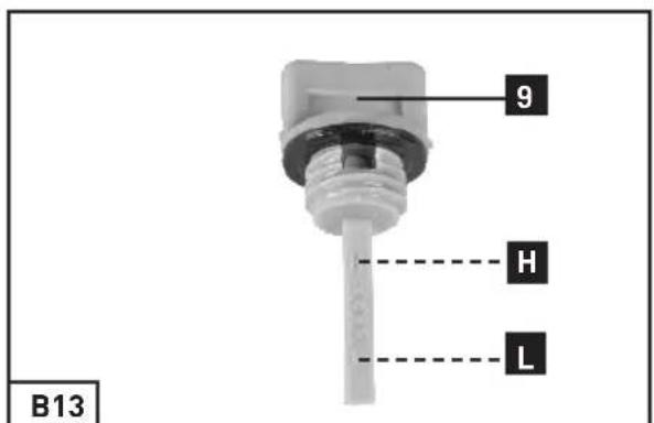
natural_image
Close-up of a hand adjusting a mechanical component with visible wiring and tire (no text or symbols)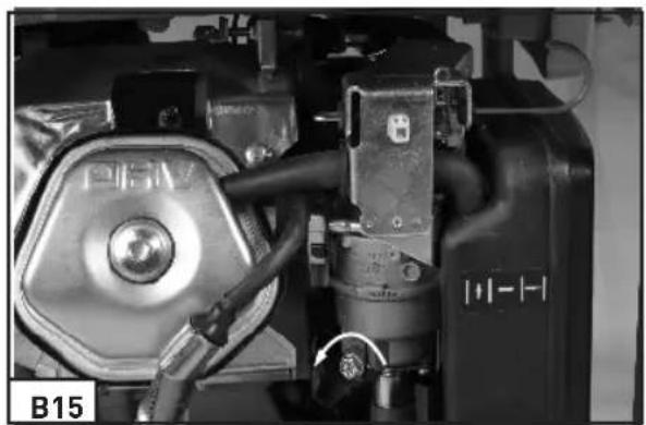
natural_image
Close-up of industrial machinery components with visible wiring and valve (no readable text or symbols)Important!
When using the equipment, a few safety precautions must be observed to avoid injuries and damage. Please read the complete operating instructions and safety regulations with due care. Keep this manual in a safe place, so that the information is available at all times.
If you give the equipment to any other person, hand over these operating instructions and safety regulations as well. We cannot accept any liability for damage or accidents which arise due to a failure to follow these instructions and the safety instructions.
1. Explanation of the warning signs and symbols on the machine
Read and understand the safety instructions before using the generator.

During operation, toxic gases are produced e.g. carbon monoxide (Which is a colorless and odorless gas) this gas may lead to by suffocation. Only operate the generator outside to ensure adequate ventilation.

Switch the engine off and allow to cool before refuelling the generator. Fuel is extremely flammable and under certain conditions can be explosive. Only refuel the generator in well ventilated areas ensuring that naked lights, sparks and cigarettes are not present. Any spillage of fuel should be immediately cleaned up.
The exhaust gets very hot during operation. Allow the engine to cool before performing maintenance storage and refueling. Do not touch the exhaust to avoid the risk of burns and injury.

The generator must not be connected to the public power supply. In case of improper connection there is a risk of fire and damage to property including electrocution to persons using the generator and working on the public power supply.
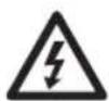
Warning hazardous voltages are present when the generator is in use, Always switch the generator off before performing maintenance.

Wear ear protection when using the generator.

Disconnect all equipment from the socket outlets when performing maintenance or when left unattended and switched off.
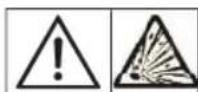
Warning: the gasoline is highly volatile, flammable and explosive
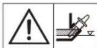
Warning: Check the oil level before operation.
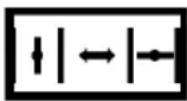
Choke lever
Petrol cock

Fuel gauge
Voltmeter
1/0
ON/OFF
Alternating current (AC)

Direct current (DC)
Overload cut-out
2. General Safety Instructions
- Important: No changes may be made to the generator.
- Only original parts may be used for maintenance and accessories.
- No changes may be made to the settings of the motor or generator. The speed preset by the manufacturer is not allowed to be changed. The generator or connected equipment may be damaged.
- Repairs and adjustment work may only be carried out by authorized trained personnel.
- Important: Petrol and petrol fumes are highly combustible or explosive.
- Risk of explosion: Never operate the
generator in rooms with combustible materials.
- Do not refuel or empty the tank near open lights, fire or sparks. Do not smoke! Important: Exhaust gases can escape despite the exhaust hose. Due to the fire hazard, never direct the exhaust hose towards inflammable materials.
- Always switch off the engine when transporting and refueling the generator.
- Make sure that when you refuel the generator, No fuel is spill on the engine or exhaust pipe.
- Place the generator in a secure, level position. Do not turn, tip or change the generator's position while it is working.
-
Secure the generator against shifting and toppling during transport.
-
Guard against electric danger.
- Make sure the generator is properly grounded before use.
- Never connect the generator to the power grid.
- Never operate the generator in rain or snow.
- Never touch the generator with wet hands.
- Never use faulty or damaged electrical equipment (this also applies to extension cables and plug connections)
- When working outdoors, use only extension cables that are approved for outdoor use and which are marked accordingly (H07RN).
-
The overall length of the extension cables used may not exceed 50 m for 1.5 mm ^4 and 100 m for 2.5 mm.
-
Important: Risk of burns. Do not touch the exhaust system or drive unit.
- The generator is driven by a combustion engine, which produces heat in the area of the exhaust (on the opposite side of the sockets) and the exhaust outlet. You should therefore keep clear of these surfaces because of risk of skin burns.
- Do not touch any mechanically driven or hot parts. Do not remove the safety guards.
- Children are to be kept away from the generator.
- Important: Danger of poisoning, do not inhale emissions.
- Never operate the generator in non-ventilated rooms. When operating the generator in rooms with good ventilation, the exhaust gases must be channeled directly outdoors through an exhaust hose.
- Place the generator at least 1m away from buildings and the equipment connected to it.
- Wear suitable ear protection when in the vicinity of the equipment.
- The values quoted in the technical data for sound power level (LWA) and sound pressure level (LWM) are emission values and not necessarily reliable workplace values. As there is a correlation between emission and emission levels, the values are not a reliable basis for deciding on any additional precautions which may be needed. Factors influencing the actual user emission level include the properties of the work area, other sound sources etc., the number of machines and other processes in the vicinity, as well as the time span in which the operator is subjected to the noise. Also, the permitted emission level can vary from country to country. Nevertheless, with this information the user is able to make a better assessment of the dangers and risks involved.
CAUTION: Read all safety regulations and instructions.
Any errors made in following the safety regulations and instructions may result in an electric shock, fire and/or serious injury. Keep all safety regulations and instructions in a safe place for future use.
3. Proper Use
The generator is intended to provide electric tools and light sources with electricity. When using the device with household appliances, please check their suitability in accordance with the relevant manufacturer's instructions. In case of doubt, ask an authorized dealer of the respective appliance. The machine is to be used only for its prescribed purpose. Any other use is deemed to be a case of misuse. The user / operator and not the manufacturer will be liable for any damage or injuries of any kind caused as a result of this.
The device is designed for applications operated with a 230V/400V alternating current source for 230V/400V.
4. Technical Data
Generator
Generator type: Synchronous
Ingress Protection: IP23M
Rated voltage Urated:
3-400 Va.c./230 Va.c. / 12V d.c.
Continuous rated power Prated (S1): 3.6 kW
Maximum power Pmax(S2):
5.5 kW (S2, 2min)
Frequency Frated: 50 Hz
Power factor: Cos=1
Performance class: G1
Operating mode S1 (continuous operation)
The machine can be continuously operated with the quoted power output.
Operating mode S2 (temporary operation)
The machine may be temporarily operated with the quoted power output. Afterwards the machine must be stopped for a while to prevent it from overheating
Engine
Engine model: PD188F
Engine design:
Single-cylinder forced air-cooled 4-stroke OHV
Spark plug: LG F6TC
Displacement: 389 cm ^4
Tank capacity: 28 L
Engine oil: Appox.1.1 l (15W40/<0 °C: 5W30)
Weight: 91 kg
Guaranteed sound power level L_WA : 97 dB(A)
Max. Temperature: 40 °C
Max. Altitude (above mean sea level): 1000 m
5. Parts Layout
-
Fuel gauge
-
Fuel cap
-
230 V\~ socket out lets.
-
400 V\~3-Phase socket
-
12Vd.c. connector out lets
-
Earth connection
-
Circuit breaker
-
Voltmeter
-
Oil filler plug
-
Oil drain nut
-
Engine switch
-
Choke lever
-
Pull cord
-
Petrol cock
-
Wheels
-
Carry handle
-
Rubber foot
-
Spanner
-
DC connecting cord
-
Wheel shaft
-
Air filter set
-
Spark plug
-
Starter key
-
Spark plug wrench set
-
230 V\~ / 400V \~transfer switch
6. Before Use.
6.1 Wheel assembly (B4-B5)
-
First place one end of the wheel shaft (item 21) through the hole in the frame and secure it with a nut and washer.
-
Put the shaft sleeve through the other end
of the wheel shaft. Then place the wheel and secure it by the nut and the washer.
3. Assemble the left side wheel with same procedures as above.
Important:
The inner wheel should be inflated for it has been shipped out with lower pressure (max. gauge pressure 3 bar/0.3 MPa).
6.2 Rubber feet assembly (B7-B8)
Hold the foot (item 17) against the frame as shown. First place the bolt through the hole into the frame and the hole in the foot and secure it with a nut. Then secure other three bolts and nuts with same procedure.
6.3 Transport handle assembly (B6)
Place the carry handle (item 16) holder against the frame as shown. Place the bolt through the hole into the frame and the hole in the handle holder. Then secure it with a nut. Then secure the other bolt with same procedure.
The user can adjust the position of carry handle. To move the generator via the rotated carry handle to open position.
6.4 Important: Electrical safety
- Electric supply cables and connected equipment must be in perfect condition.
- The generator is to be operated only with equipment whose voltage specifications conform to the generator's output voltage.
- Never connect the generator to any other power supply.
- Keep the cable length to the consumer as short as possible.
6.5 Environmental protection
- Dispose of soiled maintenance material
and operating materials at the appropriate collection point.
- Recycle packaging material, metal and plastics.
6.6 Connecting to earth
-The housing is allowed to be connected to earth in order to discharge static electricity. To do this, connect one end of a cable to the earth connection (6) on the generator and the other end to an external earth (for example an earth rod).
7. Operation.
7.1 Before starting the generator.
- You must fill up with engine oil (B12) and fuel before you can start the engine.
- Check the fuel level and top it up if necessary.
- Make sure that the generator has sufficient ventilation.
- Make sure that the ignition cable is secured to the spark plug.
- Inspect the immediate vicinity of the generator.
- Disconnect any electrical equipment which may already been connected to the generator.
- Permissible ambient temperature - 10 to +40°C, max. altitude above sea level 1000 m, relative humidity:90 %(noncondensing)
- Never use the generator in dusty area.
7.2 Starting the engine (reversing starter)
- Open the petrol cock (14) by turning it up.
- Move the engine switch (11) to position "I".
- Move the choke lever (12) to position I∅I.
- Start the engine with the pull cord (13) by pulling the handle forcefully. If the engine does not start, pull the handle again.
- Push the choke lever (12) back again after the engine has started.
Important!
When starting with the pull cord, the motor may recoil suddenly as it starts up, resulting in hand injuries. Wear protective gloves when starting the equipment.
7.3 Starting the engine (electro starter)
- Check the battery voltage. The voltage should be not less than 12V. If the battery voltage is less than 12V, charge the battery accordingly before operating the generator.
- Do not connect the power tool before starting the motor.
- Move the choke lever (12) to position I∅I.
- Open the petrol cock (14) by turning it down.
- Turn the engine switch (11) with the key to the "START" position until the motor has started.
- Push the choke lever (12) back again after the engine has started.
7.4 Connecting appliances to the generator
- Connect the equipment you want to use to the socket outlets (3,4)
Important!
- Never connect the generator to the domestic power network as this may result in damage to the generator itself or to other electrical appliances in your home.
- Switch off the machine immediately and contact your service station:
- If the generator is making unusual vibrations or noise.
If the engine is overloaded within rated load range or misfires.
Note: Some electrical appliances (power jigsaws, drills, etc.) may have a higher level of power consumption when used in difficult
conditions or starting.
- Use the supplied DC connecting cable to make connection to 12VDC powered appliance.
Important!
The DC output of the generator is not treated by a precise electric circuit.
Never use it to power any precise DC instrument.
Important!
When using the generator to powering a heating device. Please do keep the powered heating device far from the generator.
7.5 Switching off the engine
- Before you switch off the generator, allow it to run briefly with no appliances so that it can "cool down".
- Move the Engine switch (11) to position "0".
- Close the petrol cock.
7.6 Overload cut-out for socket-outlets
Important!
The generator is fitted with an overload cutout. This shuts down the sockets (4). You can restart the sockets by reset the circuit breaker (7).
Important!
If this happens, reduce the electric power you are taking from the generator or remove any defective connected appliances.
Important!
Defective overload cut-outs must be replaced only by overload cut-outs of identical design and with the same performance data. If repairs are necessary, please contact your customer service center.
8. Cleaning, maintenance and storage
Switch off the generator and pull the spark plug boot from the spark plug before doing any cleaning and maintenance work on the equipment.
8.1 Cleaning
- Keep all safety devices, air vents and the motor housing free of dirt and dust as far as possible. Wipe the equipment with a clean cloth or blow it with compressed air at low pressure.
- We recommend that you clean the device after each time finished using.
- Clean the equipment regularly with a moist cloth and some soft soap. Do not use cleaning agents or solvents; these could attack the plastic parts of the equipment. Ensure that no water can seep into the device.
8.2 Air filter (B10-11)
In this connection, please also read the service information.
- Clean the air filter at regular intervals, and replace it if necessary.
- Remove fixing bolt on the air filter cover (B10).
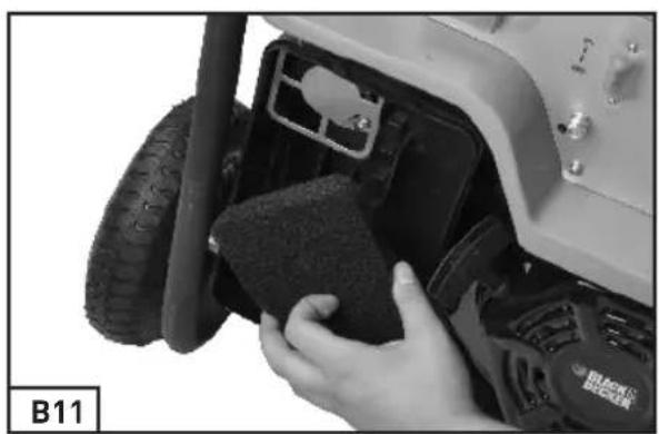
- Remove the filter elements (B11).
Important!
Do not use abrasive cleaning agents or petrol to clean the elements.
- Clean the elements by tapping them on a flat surface. In cases of stubborn dirt first clean with soapy water, and then rinse with clear water and air dry.
- Assemble in reverse order.
8.3. Spark plug (B9)
Check the spark plug (item 22) for dirt and grime after 50 hours of operation and if necessary clean with a copper wire brush. Thereafter service the spark plug after every 50 hours of operation.
- Pull off the spark plug boot with a twist.
- Remove the spark plug with the supplied spark plug wrench (24).
- Assemble in reverse order.
8.4 Changing the oil and checking the oil level (B12-B14)
The motor oil is best changed when the Engine is at working temperature.
- Only use motor oil SAE - 15W40 / (<0 °C) [SAE - 5W30].
8.4.1 Fill up Oil. (B12)
- Open the oil filler plug by screw it off (9).
- Add exactly 0.6L engine oil with an oil filling jug.
Or refer to content in 7.4.2.
- Screw the Oil filler plug back.
8.4.2 Checking Oil level. (B13)
- Place the generator on a slightly inclined surface so that the dip stick is at proper position.
- Screw off the Oil Filler plug and wipe off any oil on the dip stick.
- Put the oil dip stick back without screw into
the Oil filler.
Important!
Do not screw the dipstick in to check the oil level; simply insert it up to the thread.
- Check the dip stick; make sure the oil level is between "H" and "L" mark.
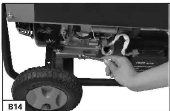
8.4.3 Let out used Oil (B14)
- Open the oil filler plug (9).
- Screw off the oil drain nut (10) and let the hot engine oil drain out into a drip tray.
- After the old oil has drained out, close the oil drain plug and place the generator on a level surface again.
8.4.4 Changing Engine Oil
- changing engine oil refers to the content in 8.4.3 and 8.4.1.
8.5 Oil shortage cut-out
This generator has a Low Oil level Protection system.
The oil shortage cut-out responds if there is too little oil in the engine. In this case it will not be possible to start the engine or it will cut out automatically after a short period of time. It cannot be started again until the engine oil has been topped up (see point 8.4.1).
8.6 Storage
If the generator is going to stop used for long time (more than 3 months).
Make sure have done following points:
- Make sure the fuel tank is empty. The fuel tank of the generator is not fully sealed. Long time fuel storage could cause fuel deteriorate.
- Make sure there is no fuel in the carburetor. To empty the carburetor. Unscrew the carburetor out let screw. Collect the fuel inside. Then screw it back on. (B15) Fuel residual could cause carburetor jamming.
- Make sure the engine is oil empty. Emptying the oil refers to the content in 7.4.3. Long time oil storage could cause oil deteriorate. Deteriorated oil could jam the oil sensor.
Important!
Never storage the generator exposed out door.
9. Transport
ATTENTION!
Slipping or falling unit can crush hands and feet.
- Carry the generator on transportation handles:
- Lift the generator evenly.
- Carry the generator to the operating place.
- Drop the generator evenly.
10. Troubleshooting
| Fault Cause Remedy | ||
| Engine does not start Oil shortage | cut-out has not respondedSpark plug fouledNo fuelBattery voltage too low | Check oil level, top up engine oilClean or replace spark plug (electrode spacing 0.6 mm)Refuel / check the petrol cockCharge the battery |
| Generator has too little or no voltage | Controller or capacitor defectiveOverload cut-off has triggeredAir filter dirty | Contact your dealerActuate the circuit-breaker and reduce the consumersClean or replace the filter |
11. Maintenance schedule
| Regular service periodPerform at every indicatedmonth or operating hourinterval, whichever comesfirst. | Eachuse | Firstmonthor20 Hrs. | Every3monthsor50 Hrs. | Every6monthsor100 Hrs. | Everyyearor200 Hrs. | |
| ITEM | ||||||
| Engine oil | Check level | 0 | ||||
| Change | 0 | 0 | ||||
| Air cleaner | Check | 0 | ||||
| Clean | 0 (1) | |||||
| Spark plug | Check-adjust | 0 | ||||
| Replace | 0 | |||||
| Spark arrester | Clean | 0 | ||||
| Valve clearance | Check-adjust | 0 (2) | ||||
| Combustion chamber | Clean | After every 300 hrs. (2) | ||||
| Fuel tank and filter | Clean | 0 (2) | ||||
| Fuel tube | Check | Every 1 year (Replace if necessary) (2) | ||||
| Remark:(1) Service more frequently when used in dusty areas.(2) These items should be serviced by your servicing dealer, Refer to the manual for service procedures.Failure to follow this maintenance schedule could result in non-warrantable failures. | ||||||
Wichtig!
Read and understand the safety instructions before using the generator.

During operation, toxic gases are produced e.g. carbon monoxide (Which is a colorless and odorless gas) this gas may lead to by suffocation. Only operate the generator outside to ensure adequate ventilation.


2. General Safety Instructions
5. Legenda (afb. 1-7)
| No. | Material name | quantity |
| 1 | Recoil starter combination | 1 |
| 2 | Tubing clamp | 2 |
| 3 | The choke valve | 1 |
| 4 | Empty filter components | 1 |
| 5 | Choke valve assembly | 1 |
| 6 | Tubing clamp | 2 |
| 7 | Reset tension spring | 1 |
| 8 | Speed adjustment bracket component | 1 |
| 9 | Control arm components | 1 |
| 10 | Speed control lever | 1 |
| 11 | Fine tuning speed spring | 1 |
| 12 | Carburetor parts | 1 |
| 13 | Carburetor joint piece | 1 |
| 14 | Carburetor paper pad | 1 |
| 15 | Air inlet paper pad | 1 |
| 16 | A cylinder head | 1 |
| 17 | Vent gasket | 2 |
| 18 | Vent stud | 2 |
| 19 | nut | 4 |
| 20 | Muffler elbow pipe combination | 1 |
| 21 | Fairing component | 1 |
| 22 | The exhaust valve hat | 1 |
| 23 | Push rod guide frame components | 1 |
| 24 | Push rod components | 2 |
| 25 | The exhaust valve | 1 |
| 26 | The spark plug parts | 1 |
| 27 | Valve spring | 2 |
| 28 | The exhaust valve spring seat | 1 |
| 29 | Inlet valve spring seat | 1 |
| 30 | Inlet valve | 1 |
| 31 | Cylinder epicranium sealing ring | 1 |
| 32 | Cylinder epicranium parts | 1 |
| 33 | Exhaust pipe | 1 |
| 34 | Air filter bracket | 1 |
| 35 | Combination valve rocker arm | 2 |
| 36 | Cylinder head positioning pin | 2 |
| 37 | Cylinder head gasket | 1 |
| 38 | The crankshaft box body parts | 1 |
| 39 | Lid seal | 2 |
| 40 | Bearings 6202 | 2 |
| 41 | To the single component | 1 |
| 42 | Bar clamp | 1 |
| 43 | The flywheel parts | 1 |
| 44 | The flywheel fan | 1 |
| 45 | Starting a cup | 1 |
| 46 | Components on the ignition coil | 1 |
| 47 | A column | 2 |
| 48 | Speed swinging rod | 1 |
| 49 | O shape clamp | 1 |
| 50 | Speed swinging rod locking clip | 1 |
| 51 | Pendulum stem seal | 1 |
| 52 | The oil alarm | 1 |
| 53 | Piston pin retainer | 2 |
| 54 | Connecting rod parts | 1 |
| 55 | The piston | 1 |
| 56 | The piston pin | 1 |
| 57 | Combination of piston ring | 1 |
| 57—1 | Tabletting ring | 2 |
| 57—2 | Oil ring | 1 |
| 57—3 | Piston ring 2 | 1 |
| 57—4 | Piston ring 1 | 1 |
| 58 | Dovetail clamps | 2 |
| 59 | Balancing shaft | 1 |
| 60 | Bearings 6207 | 1 |
| 61 | The camshaft combination | 1 |
| 62 | Governor gear parts | 1 |
| 63 | Crankcase paper pad | 1 |
| 64 | The crankshaft parts | 1 |
| 65 | Crankcase cover panel 1 | 1 |
| 66 | Oil foot parts | 1 |
| 67 | Crankcase cover over the hood | 1 |
| 68 | Crankcase cover panel 2 | 1 |
| 69 | Crankcase cover parts | 1 |
| 70 | Frame cross arm | 1 |
| 71 | Fuel tank parts | 1 |
| 71—1 | Fuel tank | 1 |
| 71—2 | The cap | 1 |
| 71—3 | Gasoline filter | 1 |
| 72 | Out of the tubing | 1 |
| 73 | Rubber tubing set | 1 |
| 74 | Under the valve spring seat | 2 |
| 75 | Oil switch (o-rings) | 1 |
| 76 | shaft | 2 |
| 77 | Pneumatic tyre | 2 |
| 78 | Wheel cover | 2 |
| 79 | Decorative side panel | 1 |
| 80 | Rack combination | 1 |
| 81 | Balance bracket | 1 |
| 82 | Frame suspension rubber gasket | 2 |
| 83 | Damping bearing A and B | 4 |
| 84 | Motor combination | 1 |
| 84—1 | Carbon brush | 1 |
| 84—2 | The motor | 1 |
| 85 | Voltage regulator combination | 1 |
| 86 Hand tube | 2 | |
| 87 Handle the glue sets 2 | ||
| 88 | Installation piece of right hand | 1 |
| 89 | Installation piece of left hand | 1 |
| 90 Muffler tailgate 1 | ||
| 91 Muffler side cover 1 | ||
| 92 | Inside the muffler cover gasket | 1 |
| 93 | Inside the muffler cover components | 1 |
| 94 Muffler parts 1 | ||
| 95 Vent gasket 1 | ||
| 96 | Muffler mounting bracket component | 1 |
| 97 Motor bracket 1 | ||
| 98 Electric tail cover 1 | ||
| 99 Panel assembly 1 | ||
| 99—1 | Panel cover 1 | |
| 99—2 | Electrical components installed version | 1 |
| 99—3 | Shut down the switch 1 | |
| 99—4 | Voltage watchcase 1 | |
| 99—5 | voltmeter 1 | |
| 99—6 | Voltage switch 1 | |
| 99—7 | Thermal protector 3 | |
| 99—8 | Grounding line column | 1 |
| 99—9 | Dc terminal 2 | |
| 99—10 | open | 1 |
| 99—11 | socket | 2 |
| 99—12 | Industrial socket | 1 |
| 100 | Crankcase dowel pin | 2 |
| 101 | bolt | 20 |
| 102 Reel nut 3 | |
| 103 The flywheel nut 1 | |
| 104 Control arms tighten bolts 1 | |
| 105 bolt 8 | |
| 106 bolt 2 | |
| 107 Speed swinging rod gasket 1 | |
| 108 Oil drain bolt 2 | |
| 109 The drain bolt washer 2 | |
| 110 Cylinder epicranium bolt components | 1 |
| 111 Flat mat 4 | |
| 112 bolt 4 | |
| 113 The gasket 12 | |
| 114 bolt 11 | |
| 115 bolt 4 | |
| 116 bolt 4 | |
| 117 Toothed washer 1 | |
| 118 bolt 2 | |
| 119 bolt 10 | |
| 120 Insert lock nut, not of metal 2 | |
| 121 Reel nut 8 | |
| 122 bolt 2 | |
| 123 nut 4 | |
| 124 The stator bolts 4 | |
| 125 Spring washers 6 | 4 |
| 126 bolt 3 | |
| 127 The stator connection bolts | 2 |
| 128 Reel nut 2 | |
| 129 Play mat | 2 |
| 130 Flat mat 1 | |
| 131 Rotor bolt | 1 |
| 132 bolt 4 | |
| 133 Exhaust tube protector | 1 |
| 134 Inlet valve cover oil baffle | 1 | |
| 135 Start the motor | 1 | |
| 136 | Battery cathode connecting line | 1 |
| 137 | Battery positive electrode wire | 1 |
| 138 The battery 1 | ||
| 139 The battery straps | 1 | |
| 140 Convenient set of | 1 | |
| 141 bolt 2 | ||
| 142 Charging coil component | 1 | |
| 143 bolt 2 | ||
| 144 Line pressing board | 1 | |
| 145 | Insert lock nut, not of metal 4 | |
hereby declares the following conformity under the EU Directive and standards for the following article
GR
Δήλωση συμμόρφωσης
This appliance is a quality product. It was designed in compliance with current technical standards and made carefully using normal, good quality materials.
The warranty period is 24 months and commences on the date of purchase, which can be verified by the receipt, invoice or delivery note. During this warranty period all functional errors, which, despite the careful treatment described in our operating manual, are verifiably due to material aws, will be rectified by our after-sales service staff.
The warranty takes the form that defective parts will be repaired or replaced with perfect parts free of charge at our discretion. Replaced parts will become our property. Repair work or the replacement of individual parts will not extend the warranty period not will it result in a new warranty period being commenced for the appliance. No separate warranty period will commence for spare parts that may be ted. We cannot offer a warranty for damage and defects on appliances or their parts caused by the use of excessive force, improper treatment and servicing.
This also applies for failures to comply with the operating manual and the installation or spare and accessory parts that are not included in our range of
products. In the event of interference with of modifications to the appliance by unauthorised persons, the warranty will be rendered void.
Damages that are attributable to improper handling, over loading, or natural wear and tear are excluded from the guarantee.
Damages caused by the manufacturer or by a material defect will be corrected at no charge by repair or by providing spare parts.
The prerequisite is that the equipment is handed over assembled, and complete with the proof of sale and guarantee.
For a guarantee claim, only use the original packaging.
That way, we can guarantee quick and smooth guarantee processing.
Please send us the appliances post-paid or request a Freeway sticker. Unfortunately we will be unable to accept appliances that are not postpaid.
The warranty does not cover parts that are subject to natural wear and tear. If you wish to make a warranty claim, report faults or order spare parts or accessories, please contact the after-sales centre below:
Subject to change without prior notice.
Matrix GmbH Service
. Mautanger 1 . D-85296 Rohrbach
- Tel.: +49 (0) 1806/841090. Fax: +49 (0) 8702/94858-28
- service@matrix-direct.net

GARANTIE
Please check our service centres at www.matrix-direct.net.

Takuu
Purchased at:
in (city, street): ____
Name of customer: ____
Street address: ____
Postal code, city: ____
Telephone:
Date, signature: ____
Fault description: ____
D GARANTIE
- Important!
- Explanation of the warning signs and symbols on the machine
- General Safety Instructions
- Proper Use
- Technical Data
- Parts Layout
- Before Use.
- Wheel assembly (B4-B5)
- Assemble the left side wheel with same procedures as above.
- Important:
- Rubber feet assembly (B7-B8)
- Transport handle assembly (B6)
- Important: Electrical safety
- Environmental protection
- Connecting to earth
- Operation.
- Before starting the generator.
- Starting the engine (reversing starter)
- Starting the engine (electro starter)
- Connecting appliances to the generator
- Switching off the engine
- Overload cut-out for socket-outlets
- Cleaning, maintenance and storage
- Cleaning
- Air filter (B10-11)
- Spark plug (B9)
- Fill up Oil. (B12)
- Checking Oil level. (B13)
- Let out used Oil (B14)
- Changing Engine Oil
- Oil shortage cut-out
- Storage
- Make sure have done following points:
- Transport
- ATTENTION!
- Troubleshooting
- Maintenance schedule
- Wichtig!
- Legenda (afb. 1-7)
- GARANTIE
- Takuu
- D GARANTIE
Brand : BLACK & DECKER
Model : BD 5500
Category : Generator