DECRNN034 - Thermostat Perry - Free user manual and instructions
Find the device manual for free DECRNN034 Perry in PDF.


| Brand | Perry |
| Model | DECRNN034 |
| Product type | Programmable room thermostat (chronothermostat) |
| Power supply | 2 alkaline 1.5 V type AA LR6 batteries (not supplied) |
| Battery life | 2 years |
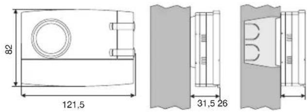
| Dimensions (H x W x D) | 121.5 x 82 x 31.5 mm |
| Weight | 0.2 kg (approx.) |
| Protection degree | IP30 |
| Insulation class | II |
| Rated impulse voltage | 4 kV |
| Output type | Relay NO/NC/Common, 5(3)A / 250 V~ |
| Allowable wire cross-section | Relay terminals: 0.75-2.5 mm²; programmer terminals: 0.5-1.5 mm² |
| Operating temperature range | 0 to +50 °C |
| Storage temperature range | -20 to +65 °C |
| Comfort/reduced setting range | +5 to +30 °C (0.1 °C steps) |
| Fixed frost protection temperature | +5 °C (not adjustable) |
| Clock accuracy | ±1 s/day |
| Programming | 48 half-hour indexes, daily or weekly |
| Operating modes | Automatic, Comfort, Reduced, Frost protection |
| Advanced functions | Input for telephone programmer, differential adjustment (0.3-0.9°C) and proportional adjustment (7-20 min) |
| Standards | EN60730-2-7, EN60730-2-9, CE |
| Maintenance | Clean with a damp cloth; replace batteries every 24 months |
Frequently Asked Questions - DECRNN034 Perry
User questions about DECRNN034 Perry
0 question about this device. Answer the ones you know or ask your own.
Ask a new question about this device
Download the instructions for your Thermostat in PDF format for free! Find your manual DECRNN034 - Perry and take your electronic device back in hand. On this page are published all the documents necessary for the use of your device. DECRNN034 by Perry.
USER MANUAL DECRNN034 Perry
CRONOTERMOSTATO DIGITALE DA PARETE WALL MOUNTING DIGITAL CHRONOTHERMOSTAT CHRONOTHERMOSTAT DIGITAL POUR MONTAGE EN SAILLIE DIGITAL RAUMTHERMOSTATUHR WANDMONTAGE CRONOTERMOSTATO DIGITAL DE SUPERFICIE

Modello giornaliero
Modello settimanale
Daily model
Weekly model
Modèle journalier
Modèle hebdomadaire

∴ m = 3/11
1
12
//
R
-
ato Bo
He

ATTENZIONE!
Autonomy from the flat battery (Symbol ▼lighting up):
Type of action, disconnection and device:
Software:
Rated impulse voltage:
Type of output:
Wire section at relay terminals:
Input for phone programmer:
Wire section at phone programmer terminals:
Type of insulation:
Protection class:
N° of programmable indices on the ring of the clock:
Minimum programmable time with key (tappet)
Pollution:
Scale of adjustment temperature via knobs:
- Comfort:
- Economy (energy saving):
Temperature limit (max t. set lock):
Anti-freeze temperature (t)
Temperature setting accuracy:
Scale of ambient temperature display:
Room temperature reading tolerance:
Operating temperature range:
Storage temperature limits:
Temperature gradient:
Type of temperature adjustment:
Clock precision:
CE Mark reference standard:
2 alkaline Penlight batteries 1.5 V type AA LR6 (DURACELL or ENERGIZER batteries recommended)
2 years
1 month
1 / BU / Electronic
Class A
4 kV
relay with changeover contact NO / COM / NC - Voltage-free - max 5(3)A / 250Vac
0.75 ÷ 2.5 mm²
for NO contact, voltage free
0.5 ÷ 1.5 mm²
class II
IP 30
1/2h
Normal
+5 ÷ +30 °C (default +20 °C) / +41 ÷ +86 °F (default +68 °F)
+5÷+30°C (default +17°C) / +41÷+86°F (default +62,6°F)
Step 0,1°C / 0,1°F
+5 °C / 41 °F (fixed not adjustable)
±0.1℃/±0.1°F
0 ÷ +50°C / +32 ÷ +122°F
±0.5℃/±0.9°F
0÷+50℃/+32÷+122°F
-20÷+65℃/ -4÷+149°F
max 1K/15 min.
ON-OFF operation with differential settable on 0.3 - 0.5 - 0.7 - 0.9 °C
Proportional operation with settable time cycles of 7-10-15-20 minutes
± 1 sec/day
LVD and EMC EN60730-2-7 EN60730-2-9
2 - OVERALL DIMENSIONS
3 - INSTALLATION GUIDELINES
Chronothermostat installation: independent-fixed
- Wall mounting - in round box - semi-recessed in rectangular box of 3modules.
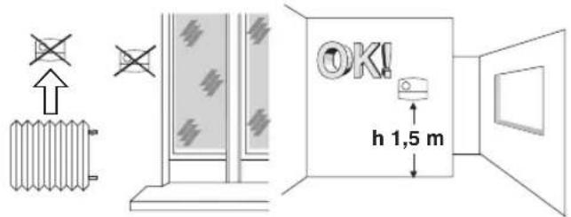
- Install the device approximately 1.5 m off the ground well away from sources of heat, windows and anything else that can affect its normal state of operation.
4 - ATTACHING THE BASE TO THE WALL
- Switch off mains power to device
- Using screws, attach the base to the wall, to the round or rectangular built-in box using the appropriate pairs of holes A.
- If the wall where the base of the chronothermostat is to be attached is metal, insert the insulating washers into the two screws.
A - attachment holes
B - wire passage from round, rectangular box
C - chronothermostat attachment teeth


To ensure the chronothermostat is correctly fitted to the base on the wall, it must not in any way be buckled due to over tightening the screws fixing to the rectangular or round box built into the wall.
5 - ELECTRICAL CONNECTIONS
Important: Installation and electrical connections of devices and appliances must be carried out by skilled people and in compliance with current regulations. The manufacturer declines all responsibility for the use of product that must conform to specific environmental and/or installation standards.
Note for the installer: If surface mounting (e.g. on a wall), have suitable raceways for the cables in compliance with current standards. Check that the relay load does not exceed the figure given in the technical data.
- Switch off mains power to the device.
- Connect the device to be controlled to the terminals:
1 - common
2-normally closed contact
3-normally open contact
Examples of electrical connections
Connection to a water heater

Connection to a

Connecting a phone programmer for remote control
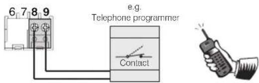
The terminals 8 and of the chronothermostat are fitted for connecting a phone programmer with a normally open contact.
Functioning with the telephone programmer
The phone programmer governs the chronothermostat closing the contact connected to terminals and .8 9
To turn on the chronothermostat with the phone programmer you need to set the switch onto one of the following types of operation: AUTOMATIC for or. tC t*
When the programmer is turned on (contact on terminals 8 and 9 closed) the chronothermostat passes from one of the conditions set with the switch to always on comfort temperature operation: besides showing all 48 indices on, the display will show the symbol for the phone programmer turned on and the Comfort symbol blinking.
Turningoff forcing with the phone programmer
Open the phone programmer contact (see programmer instructions) showing the chronothermostat in the current mode of operation at the time of switching on.
Note: Theon and off controls are operative within 1 minute.
6 - ATTACHING OR REMOVING THE CHRONOTHERMOSTAT FROM THE BASE
Fit the cable cover on by inserting the tooth D E to the slot in the base, then secure it by lightly pressing on the hooks
Use a small screwdriver to remove the cover by levering on each hook in successionF.

Hook the chronothermostat onto the base, taking care to insert the contacts correctly, then exert light pressure until you hear the click of the attachment teeth.
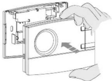

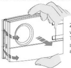
To remove the chronothermostat from the base on the wall, grip it as shown in the figure, then extract it by turning it on the right-hand side.
7- FITTING/REPLACING THE BATTERIES
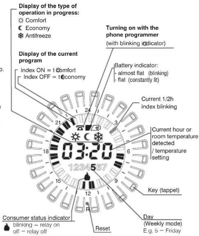
When the flashing years, this indicates that the batteries are running out. From this moment, there are 30 days to change them. If the almost flat batteries are not replaced within the indicated time, the display will turn off and the symbol will remain constantly lit.
All thermoregulation operations are suspended and all settings are saved to be restored when the new batteries are inserted.
Replace the dead batteries with two 1.5 V AA alkaline Penlight batteries (LR6) paying attention to their polarity.
CAUTION: when changing batteries, the time available to perform the operation without losing data is about 1 minute.

Dispose of flat batteries in the proper containers.

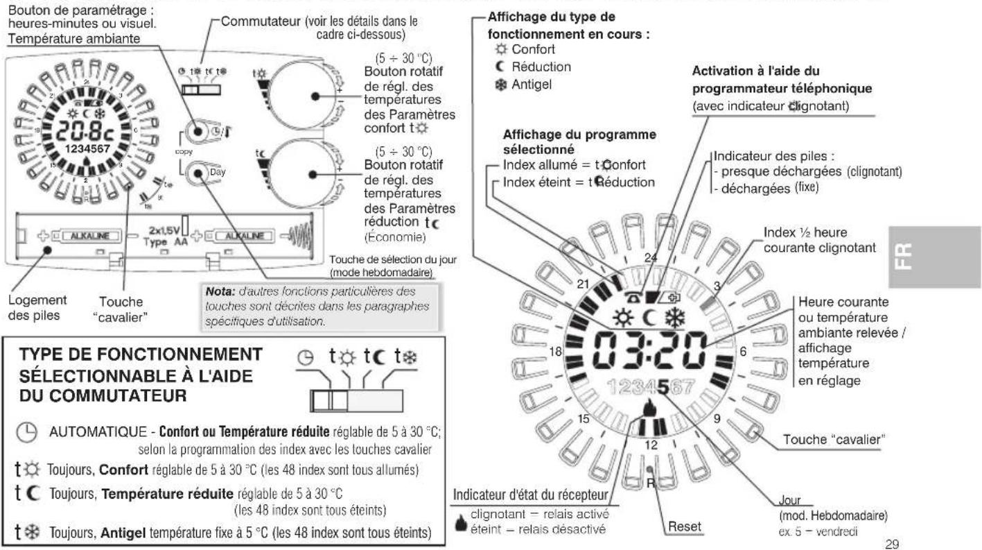
8 - GENERAL VIEW, DISPLAY LEGEND AND KEY FUNCTIONS

TYPE OF OPERATION THAT CAN BE SELECTED WITH THE SWITCH


AUTOMATIC - Comfort or Economy adjustable from 5 to 30 °C; as per indices programming with the key (tappet)

Always Comfort, adjustable from 5 to 30 °C (all 48 indices on)

Always Economy, adjustable from 5 to 30 °C (all 48 indices off)

Always Antifreeze, temperature fixed on 5 °C (all 48 indices off)
9 - RESET
When switching on for the first time or if the chronothermostat shows anomalous displays or improper functioning, etc., insert a thin rod (max 1 mm) into the hole on the ring between the key (tappet) marked Ren press briefly. The display will switch on all the segments for a few seconds. The display will show all segments for a few seconds, as shown in the diagram to the side, and all data present in the memory will be deleted, restoring all default settings (except for settings with microswitches).

The chronothermostat will be ready for programming again (see Chapter 10).
Easy Programming
All the operations described in the following paragraph can be carried out before securing the chronothermostat to the base on the wall; this allows you to do the programming while being comfortably seated.


CAUTION!
If the chronothermostat is programmed before being attached to the base on the wall, once installation is complete the symbol on the display (off or blinking) might not correspond to the actual state of the relay. Within of max 1 minute attaching the chronothermostat to the base on the wall, the relay will turn on as indicated on the display (off or blinking).
10 - PROGRAMMING
- Set the switch or AUTOMATIC operation.
IMPORTANT: do a RESET
After a few seconds, the device shows 00:00 blinking, enter the current hours and minutes as described below.
Entering current hours and minutes
- Press button ⏻/¶ to program the hour:
- keeping it pressed adjusts the hours;
- repeatedly pressing sets the minutes;
(on the daily model, wait for 5 seconds for the display to show the symbol C and the 1/2 h index corresponding to the programmed time blinking).
Entering current day(weekly model only)
The display shows day1 corresponding to Monday blinking.
- Select the day of the current week with the Dayn (wait for 5 seconds for the display to show the symbol and the half hour index corresponding to the programmed time blinking).
Programming comfort temperature at desired times
- Press and release the key (tappet) arranged in a ring on the display corresponding to the times for activating the comfort temperature (temperature level set with knob t ⚙ ), proceeding as follows:
1st press and release to activate the entire hour
2nd press and release to activate the first half hour
3rd press and release to activate the second half hour
4th press and release to deactivate the entire hour
Copying the program to other days(weeklymodel only)
- Copy programming the day you can copy it onto the next day by pressing simultaneously buttons Day 2
- If you want to set other programs, choose the day with the Day button then do the programming by pressing the key (tappet) as described above.
Displaying programs entered relating to the days of the week (weekly modelonly)
Press and release the key repeatedly.Day
Note: When you finish programming or viewing, 5 seconds after last pressing the button, the chronothermostat will automatically go into the operating state (index of the current h blinking). 1/2
It is possible at any time to pass from viewing the display of the current time to the ambient temperature (degrees centigrade) and vice versa, by briefly pressing the button.
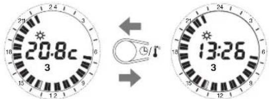
Display Set temperature t* and/or t set refer to paragraph 11
CHANGING SETTINGS
Changing the current time
- Keep ⏻/!c button pressed until the current time blinks
- Change the hour and/or minutes with the ⏰/¶ button as described above.
Changing the current day(weekly modelonly)
- Keep the Day button pressed until the number corresponding to the current day blinks.
- Set the new current day by pressing the Day button
Changing the entered programs
Daily model
- Change the program by using the key (tappet) as described above
Weekly model
- Change the program for the current day by using the key (tappet) as described above
- To change the program for the others day of the week select the desired day with the Day button and use the key (tappet) as described above
Note: when you finish making your changes, 5 seconds after last pressing the buttons, the chronothermostat will automatically go into the operating state (index of the current blinking).1/2 h
Modify T Set temperature and/or τ set refer to paragraph 11
11 - DISPLAY/MODIFY SET TEMPERATURES (via knobs): tCOMFORT / t ECONOMY
The display normally shows room temperature detected or current hours and minutes.
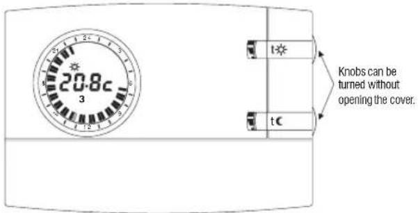
upon first start-up of the chronothermostat or after reset operation, preset default temperatures are:
Comfort Temperature Set t * = 20.0 °C/68.0°F (upper knob) Economy TemperatureSet t C = 17.0 °C / 62.6 (lowerknob)°F
In any chronothermostat operating condition, to display the current settings, simply slightly turn the relative knob until the set itself blinks. After 5 sec., the display will return to normal operation visualisation. If settings do not meet user needs, it is possible to modify them as desired at any time, from +5°C to +30 °C(from +4°F to +86°F), as per procedure shown to the side.

Perform the same procedure to set the Seteconomy temperature with knob tc
12 - COMFORT AND/OR ECONOMY TEMPERATURE MAX SET LIMIT (LOCKED SETTING)
In some particular installations, for instance in public offices, hotels, etc., it may be useful to lock the chronothermostat temperature settings to avoid incorrect settings being entered by unauthorised personnel. It will then be possible to lock the maximum Set temperature values (comfort and/or economy) as

It will then be possible to look the maximum set temperature values (comfort and/or economy) as follows:
1 - Move the switch to anti-freeze mode t (set fixed at +5°C, not adjustable)
2- Press the h23 button on the ring and the ⏻/¶ button simultaneously for 4 sec.; the display will show: b i : - (i.e. default setting = no lock).
3- Slightly turn the desired set knob (t* or t c) to view the current setting.
4- The Set will start to blink. After 3 sec., set the block setting (limit) from +5,1°C to +29,9°C, turning the knob clockwise to increase or counter-clockwise to decrease (a variation of 0.1°C at a time will be obtained).
5- If desired, repeat the operations indicated in points 3 and 4 with the other hand piece.
6- Within 20 sec., save the setting/s and exit from programming, pressing the h 23 button on the ring and button Ⓞ/☐ simultaneously for 4 sec.
7- Bring the switch back to the desired operating mode.
![graph TD A["Start"] --> B{Condition: 20 sec after 20 seconds, with no keys being turned, device will automatically exit from locked setting programming without saving any settings and will move to anti-freeze (t *) operation} B --> C{Condition: 19.0°C is marked as max cooling temperature, for both °…](/content/2026/05/807559/images/d77b49e8be1b3155a5d14513a4f9a4917c9ee00a064bf4d9aa5e4a82e514cd04.jpg)

The settings of the microswitches (dip-switches) on the back of the chronothermostat must be made by qualified personnel.
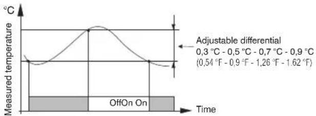
13 - TEMPERATURE DIFFERENTIAL
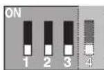
The chronothermostat works in ON-OFF differential mode (Dip 3 OFF) with the default differential setting of (0,54°F)0,3°C . The differential can be changed by moving the microswitches (dip-switches) as shown in the table.
ON
OFF
| Dip 1 | Dip 2 | Dip 3 | Differential |
| OFF | OFF | OFF | 0,3 °C (0,54 °F) |
| OFF | ON | OFF | 0,5 °C (0,9 °F) |
| ON | OFF | OFF | 0,7 °C (1,26 °F) |
| ON | ON | OFF | 0,9 °C (1,62 °F) |
The differential must be set according to the system's thermal inertia; a low setting is recommended for systems with radiators (e.g. made of cast iron) and a high setting for systems with fan-coils.
14 - PROPORTIONAL OPERATION
As an alternative to the differential, it is possible to adjust the temperature proportionally (Dip 3 ON); this system enables saving on energy consumption and also on the wear of the burner by limiting the number of ignitions. The duration of each ignition depends not only on the set cycle but also on the difference between the set temperature and the measured temperature (see example).
Example of setting t = 20°C - Cycle = 10 min
t = 20,5 °C Consumer alwaysOFF
t = 20,4 °C Consumer 1 min ON - 9 min OFF
t = 20.3 °C Consumer 2 min ON - 8 min OFF
t = 20.2 °C Consumer 3 min ON - 7 min OFF
t = 20.1 °C Consumer 4 min ON - 6 min OFF
t = 20.0 °C Consumer 5 min ON - 5 min OFF
t = 19.9 °C. Consumer 6 min ON - 4 min OFF
t = 19.8 °C Consumer 7 min ON - 3 min OFF
t = 19.7 °C Consumer 8 min ON - 3 min OFF
t = 19.7 °C Consumer 8 min ON - 2 min ON
t = 19.6 °C Consumer 9 min ON - 1 min OFF
t = 19,6 °C Consumer 9 min ON - 1 min OFF
t = 19,5 °C Consumer always ON

The duration of the cycle is determined by the position of the microswitches (dip-switches) on the back of the chronothermostat, as shown in the table. A long cycle is recommended for systems with high thermal inertia (cast-iron radiators, floor systems) and a short cycle for systems with low thermal inertia (fan-coils).
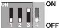
| Dip 1 | Dip 2 | Dip 3 | Duration Cycle |
| OFF | OFF | ON | 7 min |
| OFF | ON | ON | 10 min |
| ON | OFF | ON | 15 min |
| ON | ON | ON | 20 min |
15 - TEMPERATURE SCALE °C or °F

ATTENTION: the chronothermostat is preset to operate in Celsius degrees and can be modified by the installer or an expert user to function in Fahrenheit degrees (°F).
Microswitch in the back of the chronothermostat is default set to the position (Celsius degrees).
It can be moved to the ON position: the display, after performing a RESET operation, will show room and Set temperature in Fahrenheit degrees(°F).
To return to Celsius display, bring microswitch 4o the OFF position and perform a RESET operation.
In both cases, reprogramme the chronothermostat as indicated in chapter 10).

OFF = Celsius degrees (°c) range (default setting)
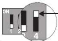
ON = Fahrenheit degrees (°F) range
16 - WARNINGS
- Please read this instruction booklet carefully and keep it for future reference.
- The figures shown in the manual depict the display with settings in C° (Celsiusdegrees).
- If the display shows an ambient temperature of 00.0 °C or 50.0 °C the measured temperature is off the scale.
- Use only 1.5V AA alkaline batteries LR6 (not included in the package), using inappropriate batteries may cause the entered programming to belost.
N.B.: The product has been tested and it ensures its characteristics with DURACELL or ENERGIZER alkaline batteries.
- Important: battery life may be more than 2 years. However, it is recommended to replace them at least every 24 months to avoid them discharging when you are away (e.g. Christmas holidays, etc.)
- If necessary, clean the chronothermostat with a slightly moist cloth.
- The manufacturer reserves the right to make all technical and manufacturing modifications deemed necessary without prior notice.

7- MISE EN PLACE OU REMPLACEMENT DES PILES
8 - VUE GÉNÉRALE LÉGENDE DES INDICATIONS AFFICHÉES ET FONCTIONS DES TOUCHES

ATTENTION!
8 - ANSICHT, LEGENDE DISPLAY UND TASTENFUNKTIONEN


ACHTUNG!


¡ATENCIÓN!
This symbol on the product or its packaging to indicates that this product shall not be treated as household waste.
Instead, it shall be handed over to the applicable collection point for the recycling of electrical and electronic equipment, such as for example:
- sales points, in case you buy a new and similar product
- local collection points (waste collection centre, local recycling center, etc...).
By ensuring this product is disposed of correctly, you will help prevent potential negative consequence for the environment and human health, which could otherwise be caused by inappropriate waste handling of this product.
The recycling of materials will help to conserve natural resources. For more detailed information about recycling of this product, please contact your local city office, your house hold waste disposal service or the shop where you purchased the product.
Attention: in some countries of the European Union, the product is not included in the field of application of the National Law that applies the European Directive 2002/96/EC and therefore these countries have no obligation to carry out a separate collection at the “end of life” of the product.

TRAITEMENT DES APPAREILSÉLECTRIQUES ET ÉLECTRONIQUES EN FIN DE VIE (directive EU 2002/96/CE)
When switching on for the first time, insert a thin rod (max 1 mm) into the hole on the ring between the key (tappet) marked R then press briefly.
RÉINITIALISATION
- CRONOTERMOSTATO DIGITALE DA PARETE WALL MOUNTING DIGITAL CHRONOTHERMOSTAT CHRONOTHERMOSTAT DIGITAL POUR MONTAGE EN SAILLIE DIGITAL RAUMTHERMOSTATUHR WANDMONTAGE CRONOTERMOSTATO DIGITAL DE SUPERFICIE
- ATTENZIONE
- OVERALL DIMENSIONS
- INSTALLATION GUIDELINES
- CHRONOTHERMOSTAT INSTALLATION: INDEPENDENT-FIXED
- ATTACHING THE BASE TO THE WALL
- ELECTRICAL CONNECTIONS
- CONNECTING A PHONE PROGRAMMER FOR REMOTE CONTROL
- FUNCTIONING WITH THE TELEPHONE PROGRAMMER
- TURNINGOFF FORCING WITH THE PHONE PROGRAMMER
- ATTACHING OR REMOVING THE CHRONOTHERMOSTAT FROM THE BASE
- FITTING/REPLACING THE BATTERIES
- RESET
- EASY PROGRAMMING
- CAUTION
- PROGRAMMING
- IMPORTANT: DO A RESET
- ENTERING CURRENT HOURS AND MINUTES
- ENTERING CURRENT DAY(WEEKLY MODEL ONLY)
- PROGRAMMING COMFORT TEMPERATURE AT DESIRED TIMES
- COPYING THE PROGRAM TO OTHER DAYS(WEEKLYMODEL ONLY)
- DISPLAYING PROGRAMS ENTERED RELATING TO THE DAYS OF THE WEEK (WEEKLY MODELONLY)
- CHANGING SETTINGS
- CHANGING THE CURRENT TIME
- CHANGING THE CURRENT DAY(WEEKLY MODELONLY)
- CHANGING THE ENTERED PROGRAMS
- DAILY MODEL
- WEEKLY MODEL
- DISPLAY/MODIFY SET TEMPERATURES (VIA KNOBS): TCOMFORT / T ECONOMY
- COMFORT AND/OR ECONOMY TEMPERATURE MAX SET LIMIT (LOCKED SETTING)
- TEMPERATURE DIFFERENTIAL
- PROPORTIONAL OPERATION
- EXAMPLE OF SETTING T = 20°C - CYCLE = 10 MIN
- TEMPERATURE SCALE °C OR °F
- WARNINGS
- MISE EN PLACE OU REMPLACEMENT DES PILES
- ATTENTION
- ACHTUNG
- ¡ATENCIÓN
- TRAITEMENT DES APPAREILSÉLECTRIQUES ET ÉLECTRONIQUES EN FIN DE VIE (DIRECTIVE EU 2002/96/CE)
- RÉINITIALISATION
Brand : Perry
Model : DECRNN034
Category : Thermostat