
Graphics 1208s - Projector Barco - Free user manual and instructions
Find the device manual for free Graphics 1208s Barco in PDF.


| Product Type | Video Projector |
| Brand | Barco |
| Model | Graphics 1208s |
| Power Supply | 230 VAC (Art. R9000893) or 120 VAC (Art. R9000896) depending on model |
| Power Consumption | Not specified; typical for CRT projectors ~1000W |
| Inputs | Composite Video (port 1, BNC loop-through with 75 ohm termination), S-Video (port 2, 4-pin mini DIN loop-through with 75 ohm), RGB Analog (port 3, D9 female; port 4/5, 5x BNC), Component Video (port 4/5 with sync options), Tri-level sync (optional) |
| Outputs | RS-232 (input and output for daisy-chain), IR remote receiver, loop-through video/S-video, remote control port (mini-jack) |
| Control | Infrared RCU (battery 9V), built-in local keypad, RS-232 for external control (PC/MAC), hardwired remote option |
| Adjustment Modes | Guided, Random Access, Installation, Service, IRIS (auto-convergence option). Includes geometry (phase, raster shift, E-W/N-S corrections), convergence (coarse/fine), focus, color balance, peaking, clamp tuning, line doubler, orbiting |
| Memory | 32 adjustment blocks; source numbers 0-9 and 90-99 for alternate settings |
| Safety | Grounded via supplied 3-wire cord; do not expose to rain/moisture; ventilation clearance of 4 inches; refer servicing to qualified personnel |
| Cleaning | Unplug before cleaning. Use soft damp cloth for cabinet; soft dry cloth for lenses (avoid touching anti-reflective coating). No liquid or aerosol cleaners |
| Operating Conditions | Ambient light must be minimized; avoid direct sunlight or fluorescent lighting onto screen; use non-reflecting dark surfaces in room |
| Options / Accessories | RCVDS 05 switcher (up to 20 inputs), VS05 switcher, IR Remote Receiver 800, Hardwired RCU, Projector Control Software, Ceiling Mount Kit CM100, Orbiting Kit, Line Doubler Kit, MAGIK interface, adapter cables |
| Dimensions | Not specified in manual; estimated cabinet dimensions ~ 600 x 500 x 800 mm |
| Weight | Not specified in manual; estimated ~ 60-80 kg |
Frequently Asked Questions - Graphics 1208s Barco
User questions about Graphics 1208s Barco
0 question about this device. Answer the ones you know or ask your own.
Ask a new question about this device
Download the instructions for your Projector in PDF format for free! Find your manual Graphics 1208s - Barco and take your electronic device back in hand. On this page are published all the documents necessary for the use of your device. Graphics 1208s by Barco.
USER MANUAL Graphics 1208s Barco
Due to constant research, the information in this manual is subject to change without notice.
Produced by BARCO NV, January 1997.
All rights reserved.
Trademarks are the rights of their respective owners.
Printed in Belgium
BARCO nv/Projection Systems
Noordlaan 5
B-8520 Kuurne
Belgium
Printed in Belgium
Table of contents ...... i
Safety instructions 1-1
On safety 1-1
On installation 1-2
On servicing 1-2
On cleaning 1-2
On repacking 1-2
On illumination....1-2
Location and Functions of Control 2-1
Rear panel terminology 2-1
Front panel terminology 2-1
Control panel terminology 2-2
a. The Local Keypad 2-2
b. RCU control panel terminology 2-2
Connections 3-1
AC Power (mains) Cord Connection 3-1
Power Check 3-1
Switching On/Off 3-1
Signal Input Connection to the Projector : 3-2
Connecting a Composite Video source to port 1. 3-3
Connecting a S-Video or Video source to port 2. 3-3
Connecting a RGB Analog source to port 3. 3-4
Connecting a RGB Analog source to port 4/5. 3-4
Connecting a RGB Analog source with Tri-level sync to port 4/5.(option) 3-5
Connecting a Component Video source to port 4/5. 3-5
Connecting a Component Video source with Tri-level sync to port 4/5.(Opion) 3-5
Peripheral equipment 3-6
Connecting a RCVDS 05 switcher to the BARCOGRAPHICS 808s 3-6
Connecting a VS05 switcher to the BARCOGRAPHICS 808s. 3-6
Connecting an IR Remote Receiver to the BARCOGRAPHICS 808s 3-6
Controlling 4-1
Battery installation in the RCU. 4-1
How to use your RCU 4-2
Projector Address 4-2
How to display a projector address? 4-3
How to program an address into the RCU? 4-3
Input selection 4-3
Analog Picture Controls 4-4
Controlling chained projectors. 4-4
Start up of the Adjustment Mode 5-1
Adjustment Mode 5-1
Random Access Adjustment Mode 6-1
Starting-Up the Random Access Adjustment mode 6-1
Overview 'Random Access Adjustment' mode 6-1
Selecting Setup Pattern 6-3
Internal Cross Hatch Pattern 6-3
Random access adjustment mode selection menu. 6-4
Picture Tuning 6-4
Color Balance 6-4
Sync Fast/Slow Adjustment 6-5
Peaking 6-5
Clamp Tuning 6-5
Port 2 : Video or S-Video 6-6
Line Doubler 6-6
Color Select 6-6
Focusing 6-7
Focusing color select....6-7
Blue on source 6-7
Geometry Adjustments 6-8
Horizontal Phase Adjustment 6-8
Raster Shift Adjustment 6-9
Left-Right (east-west) Adjustments 6-10
Seagull correction 6-11
Left Side Correction 6-11
Top-Bottom (north-south) Adjustments 6-12
Seagull Correction 6-13
Horizontal Size Adjustment....6-13
Vertical Linearity Adjustment 6-14
Vertical Size Adjustment 6-14
Blanking Adjustments 6-15
Convergence Adjustment 6-16
Service mode 7-1
Starting up the Service mode. 7-1
Overview flowchart 'Service' mode. 7-1
Identification 7-2
Copy a block 7-2
Deletion of blocks 7-3
Deleting block by block 7-3
Deletion of all blocks 7-3
Change password 7-4
Change Language 7-4
Run time 7-4
Set to midposition 7-5
Undo Midposition 7-5
Convergence Mid 7-5
Undo Convergence Mid(position) 7-5
Dynamic Astigmatism (spot shape adjustment) 7-6
G2 Adjust 7-7
Gamma corrections 7-7
CRT run in cycle 7-7
Projector Warm Up 7-8
CRT Drive Mode 7-8
Messages, warnings and failures 8-1
Options 9-1
Appendix A : Orbiting ...... A-1
Appendix B : Adjsutment Blocks and Source Numbers 90-99 ...... B-1
SAFETY INSTRUCTIONS
Notice on Safety
This equipment is built in accordance with the requirements of the international safety standards EN60950, UL 1950 and CSA C22.2 No.950, which are the safety standards of information technology equipment including electrical business equipment.
These safety standards impose important requirements on the use of safety critical components, materials and isolation, in order to protect the user or operator against risk of electric shock and energy hazard, and having access to live parts.
Safety standards also impose limits to the internal and external temperature rises, radiation levels, mechanical stability and strength, enclosure construction and protection against the risk of fire.
Simulated single fault condition testing ensures the safety of the equipment to the user even when the equipment's normal operation fails.
INSTALLATION INSTRUCTIONS
Before operating this equipment please read this manual thoroughly, and retain it for future reference.
Installation and preliminary adjustments should be performed by qualified BARCO personnel or by authorized BARCO service dealers.
OWNER'S RECORD
The part number and serial number are located at the back side of the projector. Record these numbers in the spaces provided below. Refer to them whenever you call upon your BARCO dealer regarding this product.
PART NUMBER :
SER. NUMBER :
DEALER :
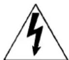
The lightning flash with an arrowhead within a triangle is intended to tell the user that parts inside this product may cause a risk of electrical shock to persons.
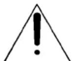
The exclamation point within a triangle is intended to tell the user that important operating and/or servicing instructions are included in the technical documentation for this equipment.
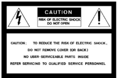
WARNING TO PREVENT FIRE OR ELECTRICAL SHOCK HAZARD, DO NOT EXPOSE THIS EQUIPMENT TO RAIN OR MOISTURE
FEDERAL COMMUNICATION COMMISSION (FCC STATEMENT)
This equipment has been tested and found to comply with the limits of a class A digital device, pursuant to Part 15 of the FCC Rules. These limits are designed to provide reasonable protection against harmful interference when the equipment is operated in a commercial environment. This equipment generates, uses and can radiate radio frequency energy and, if not installed and used in accordance with the instruction manual, may cause harmful interference to radio communications. Operation of this equipment in a residential area is likely to cause harmful interference in which case the user will be required to correct the interference at his own expense.
Note :
The use of shielded cables is required to comply within the limits of Part 15 of FCC rules and EN55022.
* All the safety and operating instructions should be read before using this unit.
* The safety and operating instructions manual should be retained for future reference.
* All warnings on the equipment and in the documentation manuals should be adhered to.
* All instructions for operating and use of this equipment must be followed precisely.
On safety
- This product should be operated from an AC power source. This projector may be connected to an IT-power system.
Operating AC power voltage of the projector:
BARCOGRAPHICS 1208s
Art. No. R9000893 → 230V AC
Art. No. R9000896 → 120V AC
Consult your dealer to switch over from 230Vac to 120 Vac or from 120Vac to 230 Vac.
If you are not sure of the type of AC power available, consult your dealer or local power company.
- This product is equipped with a 3-wire grounding plug, a plug having a third (grounding) pin. This plug will only fit into a grounding-type power outlet. This is a safety feature. If you are unable to insert the plug into the outlet, contact your electrician to replace your obsolete outlet. Do not defeat the purpose of the grounding-type plug.
WARNING FOR THE CUSTOMERS: THIS APPARATUS MUST BE GROUNDED (EARTHED) via the supplied 3 conductor AC power cable.
(If the supplied power cable is not the correct one, consult your dealer.)
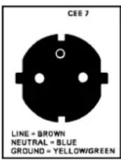
A. Mains lead (Power cord) with CEE 7 plug:
The wires of the mains lead are colored in accordance with the following code.
Green and yellow: earth (safety earth) Blue: neutral Brown: line (live)
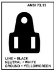
B. Power cord with ANSI 73.11 plug:
The wires of the power cord are colored in accordance with the following code.
Green/yellow: ground White: neutral Black: line (live)
- Do not allow anything to rest on the power cord. Do not locate this product where persons will walk on the cord.
To disconnect the cord, pull it out by the plug. Never pull the cord itself.
-
If an extension cord is used with this product, make sure that the total of the ampere ratings on the products plugged into the extension cord does not exceed the extension cord ampere rating. Also make sure that the total of all products plugged into the wall outlet does not exceed 15 amperes.
-
Never push objects of any kind into this product through cabinet slots as they may touch dangerous voltage points or short out parts that could result in a risk of fire or electrical shock.
Never spill liquid of any kind on the product. Should any liquid or solid object fall into the cabinet, unplug the set and have it checked by qualified service personnel before resuming operations.
- Lightning - For added protection for this video product during a lightning storm, or when it is left unattended and unused for long periods of time, unplug it from the wall outlet. This will prevent damage to the projector due to lightning and AC power-line surges.
On installation
-
Do not place this equipment on an unstable cart, stand, or table. The product may fall, causing serious damage to it.
-
Do not use this equipment near water.
-
Slots and openings in the cabinet and the back or bottom are provided for ventilation; to ensure reliable operation of the product and to protect it from overheating, these openings must not be blocked or covered. The openings should never be blocked by placing the product on a bed, sofa, rug, or other similar surface. This product should never be placed near or over a radiator or heat register.
The projector should not be placed in a built-in installation or enclosure unless proper ventilation is provided.
- Do not block the projector cooling fans or free air movement under and around the projector. Loose papers or other objects may not be nearer to the projector than 4" on any side.
On servicing
Do not attempt to service this product yourself, as opening or removing covers may expose you to dangerous voltage potentials and risk of electric shock!
Refer all servicing to qualified service personnel.
Unplug this product from the wall outlet and refer servicing to
qualified service personnel under the following conditions:
a. When the power cord or plug is damaged or frayed.
b. If liquid has been spilled into the equipment.
c. If the product has been exposed to rain or water.
d. If the product does not operate normally when the operating instructions are followed.
Note : Adjust only those controls that are covered by the operating instructions since improper adjustment of the other controls may result in damage and will often require extensive work by a qualified technician to restore the product to normal operation.
e. If the product has been dropped or the cabinet has been damaged.
f. If the product exhibits a distinct change in performance, indicating a need for service.
Replacement parts - When replacement parts are required, be sure the service technician has used original BARCO replacement parts or authorized replacement parts which have the same characteristics as the BARCO original part. Unauthorized substitutions may result in degraded performance and reliability, fire, electric shock or other hazards. Unauthorized substitutions may void warranty.
Safety check - Upon completion of any service or repairs to this projector, ask the service technician to perform safety checks to determine that the product is in proper operating condition.
On cleaning
Unplug this product from the wall outlet before cleaning. Do not use liquid cleaners or aerosol cleaners. Use a damp cloth for cleaning.
- To keep the cabinet looking brand-new, periodically clean it with a soft cloth. Stubborn stains may be removed with a cloth lightly dampened with mild detergent solution. Never use strong solvents, such as thinner or benzine, or abrasive cleaners, since these will damage the cabinet.
- To ensure the highest optical performance and resolution, the projection lenses are specially treated with an anti-reflective coating, therefore, avoid touching the lens. To remove dust on the lens, use a soft dry cloth. Do not use a damp cloth, detergent solution, or thinner.
On repacking
Save the original shipping carton and packing material; they will come in handy if you ever have to ship your equipment. For maximum protection, repack your set as it was originally packed at the factory.
On illumination
In order to obtain the best quality for the projected image, it is essential that the ambient light which is allowed to fall on the screen be kept to an absolute minimum.
When installing the projector and screen, care must be taken to avoid exposure to ambient light directly on the screen. Avoid adverse illumination on the screen from direct sunlight or fluorescent lighting fixtures.
The use of controlled ambient lighting, such as incandescent spot light or a dimmer, is recommended for proper room illumination. Where possible, care should also be taken to ensure that the floors and walls of the room in which the projector is to be installed are non-reflecting, dark surfaces. Brighter surfaces will tend to reflect and diffuse the ambient light and hence reduce the contrast of the projected image on the screen.
LOCATION AND FUNCTION OF CONTROLS
REAR PANEL TERMINOLOGY
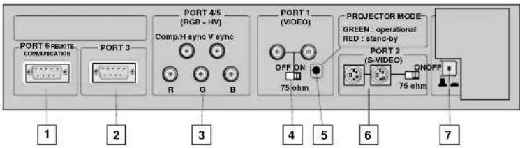
1 Communication Port (800 peripherals)
* allows communication between the RCVDS switcher and the projector.
* allows connection of a remote IR receiver unit to the projector.
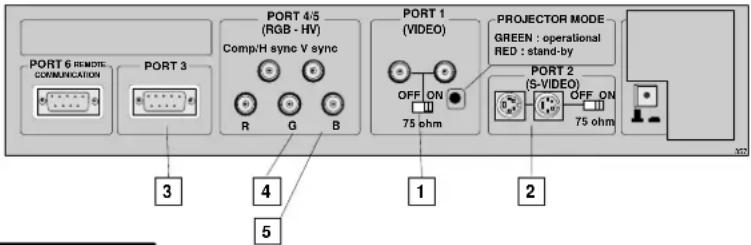
2 Port 3 RGB Analog Input (9 pin female sub D connector). Allows a character generator, microcomputer, etc. having analog RGB outputs to be connected to the projector.
3 Port 4/5 : RGB-S Input (5x BNC connector): RGB-S input : allows a character generator, microcomputer, video camera, etc. having analog RGB output to be connected to the projector.
Line inputs: - signals RED-GREEN-BLUE - COMPOSITE sync. signal - Tri level sync signal (option)
4 VIDEO Input (Composite video, 2x loop-through BNC connector): allows a video tape recorder, video camera, color receiver/monitor, etc. having video line output to be connected to the projector.
75 ohm Termination Switch for Video signals
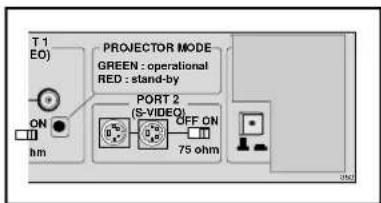
Projector Pilot Lamp : indicates the status of the projector.
- unlit : mains (power) switch is not pressed.
- lit : mains (power) switch is pressed and the indicated color shows the projector mode:
Green color : operational mode of the projector.
Red color : standby mode of the projector.
Important : projector ("Operational" or "Standby") mode is defined during the installation of the projector. (Refer to a qualified technician for change).
6 S-VIDEO Input: Separated Y/C (luma-chroma) signal inputs and outputs for higher quality playback of Super VHS signals (4-pin S-VIDEO connector loop-through).
75 ohm Termination Switch for S-Video signals
7 Power Switch : press the switch to turn the projector ON.
Depending on the hardware set-up of the projector during installation, the projector switches to 'Standby' or to 'Operational' mode. If in standby, the standby LED lights up.
FRONT PANEL TERMINOLOGY
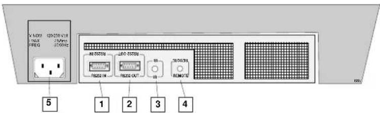
1 RS 232 Input Port Connection between the projector and an IBM PC (or compatible) or MAC (RS422) for remote computer control and data communication.
2 RS 232 Output Port RS 232 Input Port allows a communication link for PC or MAC to the next projector in a series of projector.
3 IR Sensor receiver for control signals transmitted from the RCU.
4 IR Remote Connector for remote input for hard wired remote control
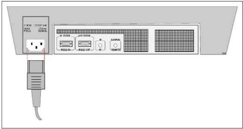
4 Power (mains) input Connect the supplied ac power (mains) cord here and to the wall outlet.
stand-by
pause/park
sharpness
tint
color
brightness
contrast


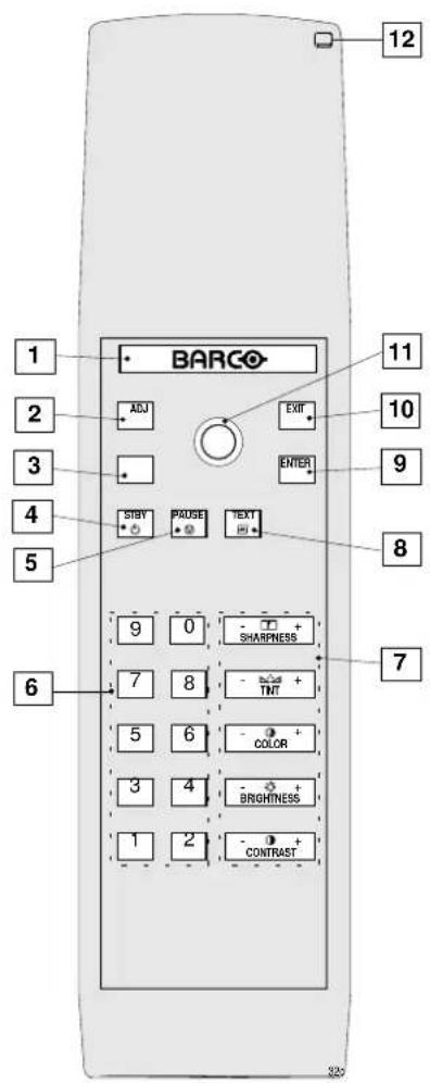
b. RCU control panel terminology
This remote control includes a battery powered infrared (IR) transmitter that allows the user to control the projector remotely.
This remote control is used for source selection, control, adaptation and set-up. It includes automatic storing of :
- picture controls (Brightness, Sharpness,...)
- picture geometry adjustments
- convergence adjustments
Other functions of the remote control are:
- switching between standby and operational modes
- switching to "pause" (blanked picture, full power for immediate restarting)
- direct access to all connected sources
- variable adjustment speed : when pushing continuously on the control stick or the picture keys, the adjustment will be executed in an accelerated fashion.
1 Back light key: when activated, all keys will be lit up and visible in the dark.
2 ADJ.: adjust key, to enter or exit the adjustment mode.
3 Address key (recessed key), to enter the address of the projector (between 0 and 9). Press the address key, followed by pressing one digit button between 0 and 9.
4 STBY : stand by button :
- to initiate remote power up operation
- to stop projection without main power off.
5 Pause :to blank the image, press PAUSE. The image disappears but full power is retained for immediate restarting.
6 Digit buttons : direct input selection.
7 Picture controls : use these buttons to obtain the desired level (see also 'Controlling') for each picture function.
8 TEXT: when adjusting one of the image controls during a meeting, the displayed bar scale can be removed by pressing 'TEXT' key first. To re-display the bar scale on the screen, press 'TEXT' key again. 'TEXT' key is only active in operational mode. When 'TEXT' is off, no warning message will be displayed.
9 ENTER: to start up the adjustment mode or to confirm an adjustment or selection in the adjustment mode.
10 EXIT: to leave the adjustment mode or to scroll upwards when in the adjustment mode.
11 Control stick key : to make menu selections when in the adjustment mode. Also allows to increment or decrement an adjustment in the adjustment mode.
control stick forward = up arrow in the menus
control stick backward = down arrow in the menus
control stick to the right = arrow to the right on the menus
control stick to the left = arrow to the left on the menus
12 RC operating indication : lights up when a button on the remote control is pressed. (This is a visual indicator to check the operation of the remote control)
CONNECTIONS
AC Power (mains) Cord Connection
Use the supplied power cord to connect your projector to the wall outlet. Plug the female power connector into the male connector at the backside of the projector.
Power Check
Power voltage indication on sticker on the back side of the projector. The power voltage is indicated by the art. no.
Warning!
Check if the indicated power voltage corresponds to that of the wall outlet.
Art. No. R9000893 must be connected to a 230 VAC power source. Art. No. R9000896 must be connected to a 120 VAC power source.
If the wall outlet voltage is different, call a qualified technician for power adaptation of the projector.
Switching On/Off
The projector is switched ON and OFF using the power (mains) switch ON/OFF.
Pressed : ON
Not pressed : OFF
The projector can start now in the 'operational mode' (image displayed) or in the 'stand by mode', depending on the position of the 'power up' dip switch on the controller unit. This DIP switch must be set during installation by a qualified technician. If you want to change this start up mode, call a qualified technician.
Stand by indication lamp :
no light up : projector switched off green color : projector in Operational mode red color : projector is in Standby mode.
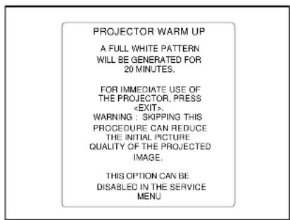
When starting up the projector, with the power switch or via the stand-by key, the projector can start up in two ways if the "CRT run in" cycle option is switched OFF.
- full white image (projector warm up) or
- immediately image display.
The way of starting up can be set in the service mode.
Start up with full white image.
The next menu will be displayed for 30 seconds.
a. Start up with warm up period.
If no action is taken, a white image will be displayed for 20 minutes.
This white image will be shifted on the faceplate of the CRT to avoid a CRT burn in.
During this warm up period, it is possible to interrupt this white image projection by pressing the EXIT key. The previous menu will be repeated for another 30 seconds but the remaining time will be indicated.
If EXIT is pressed, the remaining warm up period will be shipped.
During the warm up period, every 30 seconds a text box with the remaining time will be displayed on the screen for 2 seconds. This text box will be displayed every time on another place.
If another key, different from EXIT, is pressed, a text box with following text will be displayed :
Please use
b. Start up without warm up period.
If the EXIT key is pressed, the warm up period will be skipped and the projector is immediately ready for use.
Warning : skipping this warm up procedure can reduce the initial picture quality of the projected image.
Signal Input Connection to the Projector :
- Composite Video
- S-Video
- RGBS or RGsB
- RGB3S or RG3sB (option)
| Port No Projector input Press Digit Button | ||
| 1 Comp. | Video 1 | |
| 2 S-Video | ^1 /Comp. Video* 2 | |
| 3 RGB | ^2 | 3 |
| 4/5 RGB | ^2 | 4 or 5 |
| 4/5 Component video | ^3 | 6 |
| 4/5 RGB | with Tri level sync ^4 | 7 |
| 4/5 Component video with Tri-level sync ^5 | 8 | |

Only available when the optional Tri-level sync module is installed.
Connecting a Composite Video source to port 1.
Composite video signals from a VCR, OFF air signal decoder, etc.. flowchart
graph TD
    A["PORT 6 REMOTE COMMUNICATION"] --> B["PORT 3"]
    B --> C["COMP/H sync V sync"]
    C --> D["R"]
    C --> E["G"]
    C --> F["B"]
    G["PORT 1 (VIDEO)"] --> H["OFF ON 75 ohm"]
    I["PORT 2 (S-VIDEO)"] --> J["OFF ON 75 ohm"]
    K["PORT 4/5 (RGB - HV)"] --> L["Composite video"]
    M["TO: Next projector or to a monitor"] --> N["to next projector or to a monitor"]
    O["TV tuner, e.g. TVDM40 stereo"] --> P["VCR"]
    Q["Audio amplifier"] --> R["..."]
    S["..."] --> T["..."]
Video input selection :
with the RCU or the build in RCU : press digit button 1 \* Note : if using the loop-through Video output, then set the Termination Switch to the "OFF" position.Connecting a S-Video or Video source to port 2.
Separate Y-luma/C-chroma signals for higher quality playback of Super VHS signals. 4 pin connector configurations: Input selection
with the RCU or the build in RCU : press digit button 2 Depending on the priority setting in the Picture Tuning menu, Video or S-Video can be displayed. If the setting is not correct, start up the adjustment mode by pushing on the ADJUST key. Select 'Random Access' and press ENTER. Select 'Selected source' and press ENTER. Highlight 'Picture Tuning' and press ENTER. Highlight Port 2 : Video and press ENTER to toggle between VIDEO or S-VIDEO. Press EXIT to return. Press ADJUST to return to operational mode. \* Note: When using the Port 2 loop-through output, set the Termination Switch in the "OFF" position.  flowchart
graph TD
    A["Luma/Chroma"] --> B["VCR S-VHS"]
    A --> C["to next projector or to a monitor"]
    D["Audio amplifier"] --> C
Connecting a RGB Analog source to port 3.
Connect your RGB source via an interface to Port 3. Always use an interface when a computer and local monitor have to be connected to the projector. Barco interfaces which can be applied : Universal analog interface R9826100 RGB 120 MHz analog interfaceR9826570 VGA interface 120V R9828079 230V R9828070 MAC interface 120V R9828059 230V R9828050 MAGIK interface 120V R9828129 & R9828128 230V R9828120 & R9828121 RGB analog input with automatic sync detection. (Separate H and V sync inputs, with composite sync input or with sync signals on green) Pin configuration D9 connector of the Analog input. 1 not connected 2 ground RGBS 3 RED 4 GREEN 5 BLUE 6 ground RGBS 7 ground RGBS 8 Hor/comp. sync 9 Vert. syncAnalog Input Selection :
with the RCU or build in RCU, press digit button 3.Connecting a RGB Analog source to port 4/5.
RGB analog input terminals with separate H and V sync inputs, with composite sync input or with sync signals on green (automatic sync detection). Always use an interface when a computer and local monitor have to be connected to the projector. See 'Connecting a RGB Analog source to port 3' for a list of BARCO interfaces which can be applied. flowchart
graph TD
    A["PORT 5 REMOTE COMMUNICATION"] --> B["PORT 3"]
    B --> C["COMP/H sync V sync"]
    C --> D["R"]
    C --> E["G"]
    C --> F["B"]
    G["PORT 4/5 (RGB - HV)"] --> H["OFF ON 75 ohm"]
    I["PORT 1 (VIDEO)"] --> J["OFF ON 75 ohm"]
    K["PORT 2 (S-VIDEO)"] --> L["OFF ON 75 ohm"]
    M["Analog Interf. 120MHz INPUT"] --> N["ON R G H NP NP"]
    O["Computer"] --> P["361"]
RGB input selection :
(RGB : R, G, B signals with automatic sync detection) with the RCU or the build in RCU : press digit button 4 or 5Connecting a RGB Analog source with Tri-level sync to port 4/5. (option)
RGB analog input terminals with Tri level sync input or with Tri-level sync on green. The projector detects automatically where the sync signal is located. flowchart
graph TD
    A["PORT 6 REMOTE, COMMUNICATION"] --> B["PORT 3"]
    C["PORT 4/5 (RGB - HV)"] --> D["Comp/H sync V sync"]
    E["PORT 1 (VIDEO)"] --> F["OFF ON 75 ohm"]
    G["PORT 2 (S-VIDEO)"] --> H["OFF ON 75 ohm"]
    I["VCR HDTV player"] --> J["Audio amplifier"]
    style A fill:#f9f,stroke:#333
    style C fill:#f9f,stroke:#333
    style E fill:#f9f,stroke:#333
    style G fill:#f9f,stroke:#333
    style I fill:#ccf,stroke:#333
RGB input selection :
(RG3sB : R, G, B signals with automatic Tri-level sync detection) with the RCU or the build in RCU : press digit button 7Connecting a Component Video source to port 4/5.
A component video (R-Y, Y, B-Y) with sync signals can be connected to the projector via the Port 4/5. The projector detects automatically where the sync signal is located. flowchart
graph TD
    A["VCR HDTV player"] --> B["Audio amplifier"]
    B --> C["PORT 2 (S-VIDEO)"]
    C --> D["PORT 1 (VIDEO)"]
    D --> E["PORT 4/5 (RGB - HV)"]
    E --> F["PORT 6 Remote Communication"]
    E --> G["Port 3"]
    E --> H["Port 1"]
    E --> I["Port 2"]
    style A fill:#f9f,stroke:#333
    style B fill:#ccf,stroke:#333
    style C fill:#cfc,stroke:#333
    style D fill:#fcc,stroke:#333
    style E fill:#cff,stroke:#333
    style F fill:#ffc,stroke:#333
    style G fill:#ffc,stroke:#333
    style H fill:#ffc,stroke:#333
    style I fill:#ffc,stroke:#333
To select the component video input :
with the RCU or the build in RCU : press digit button 6.Connecting a Component Video source with Tri-level sync to port 4/5. (Opion)
A component video (R-Y, Y, B-Y) with Tri-level sync signals can be connected to the projector via the Port 4/5. The projector detects automatically where the sync signal is located. flowchart
graph TD
    A["VCR HDTV player"] --> B["Audio amplifier"]
    B --> C["PORT 2 (S-VIDEO)"]
    C --> D["PORT 1 (VIDEO)"]
    D --> E["PORT 4/5 (RGB - HV)"]
    E --> F["PORT 6 Remote Communication"]
    E --> G["PORT 3"]
    E --> H["R"]
    E --> I["G"]
    E --> J["B"]
    C --> K["75 ohm OFF ON"]
    style A fill:#f9f,stroke:#333
    style B fill:#ccf,stroke:#333
    style C fill:#cfc,stroke:#333
    style D fill:#fcc,stroke:#333
    style E fill:#cff,stroke:#333
    style F fill:#ffc,stroke:#333
    style G fill:#ffc,stroke:#333
    style H fill:#ffc,stroke:#333
    style I fill:#ffc,stroke:#333
    style J fill:#ffc,stroke:#333
To select the component video input :
with the RCU or the build in RCU : press digit button 8.PERIPHERAL EQUIPMENT
Connecting a RCVDS 05 switcher to the BARCOGRAPHICS 1208s
- Up to 20 inputs with the RCVDS 05 switcher and up to 90 inputs when 10 RCVDS switchers are linked via the expansion modules. - Serial communication with the projector. - Remote control buttons on the RCVDS to control the BARCOGRAPHICS 1208s (source selection and analog settings) - The selected source number will be displayed on a 2 digit display and the selected input modules will be indicated with a LED on the rear. For more information about the use of tje RCVDS, consult the Owner's Manual of the RCVDS. Order number : RCVDS05 : R5975765Connecting a VS05 switcher to the BARCOGRAPHICS 1208s.
The VS05 can switch up to 5 Composite Video sources, 3 S-Video Sources and 1 RGB analog or component Video source to the BARCOGRAPHICS 1208s. In addition, an audio signal associated with the source, can be switched to an audio amplifier. Order number : R9827890. For more information about the use of the VS05, consult the VS05 Owner's Manual, order number : R5975245.Connecting an IR Remote Receiver to the BARCOGRAPHICS 1208s
This infra-red receiver unit makes it possible to control the BARCOGRAPHICS 1208s from another room. There is a communication line cable between the IR receiver and the projector or the RCVDS 800. The infrared control information from the Remote Control Unit is sent to the IR Remote Receiver. The IR Remote Receiver 800 displays the selected source on a 7-segment display. Order number : R9827515. CONTROLLING
Caution : Do not display a stationary image with full brightness and contrast for longer than 20 min., otherwise you risk damage to the CRT's.Battery installation in the RCU.
A new battery (not yet installed to save the battery life) is delivered inside the plastic bag with the power cord. Before using the RCU, follow the battery installation procedure. Remove the battery cover on the backside of the RCU by pushing the indicated handle a little to the bottom of the RCU. Lift up the top side of the cover at the same time (fig. 1). Insert the new 9 V battery (type 6F22S or equivalent) in the lower compartment and connect the battery to the contact plate. Insert the battery into the lower compartment and put the cover back.  natural_image
Illustration of a person standing on a platform inside a cylindrical device (no text or symbols visible)How to use your RCU
a) Point the front of the RCU towards the reflective screen surface  b) Point the front of the RCU towards one of the IR sensors in the projector. When using the wireless remote control, make sure you are within the effective operating distance (30m, 100ft in a straight line). The remote control unit will not function properly if strong light strikes the sensor window or if there are obstacles between the remote control unit and the projector's IR sensor. IR Receiver Locations on the Projector:  c) RCU used in a hardwired configuration.  Plug one end of the remote cable in the connector on the bottom of the RCU and the second side in the connector in the rear panel of the BARCOGRAPHICS 1208s labelled 'REMOTE'. d) Built-in RCU (local keypad) To gain access to the built-in RCU, see paragraph 'The local keypad'Projector Address
a. hardware set up of the projector address. Every projector requires an individual address between 0 and 255 which is set with hardware DIP switches inside the projector. To change that address, contact a BARCO authorized technician. b. How to control the projector. The projector's address may be set to any value between 0 and 255. When the address is set, the projector can be controlled now with : - the RCU for addresses between 1 and 9. \- computer, e.g. IBM PC (or compatible), Apple MAC, etc. for addresses between 0 and 255. Note : a projector will respond to a RCU set to an address of '0' regardless of what address is set in the projector itself. Address "O" is therefore a universal address. c. Using your RCU. Before using your RCU, it is necessary to enter the projector address into the RCU (only when that address is between 1 and 9). The projector with the corresponding address will listen to that specific RCU. When address 0, 'zero address' is programmed into the RCU, every projector, without exception will listen to the commands given by this RCU.How to display a projector address?
Press the ADDRESS key (recessed key on the RCU) with a pencil. The projector's address will be displayed in a 'Text box'. This text box  disappears after a few seconds. To continue using your RCU, it is necessary to enter the same address with the digit buttons (address between 0 and 9). For example, if the Adress Key displays projector address 003, then press the "3" digit button on the RCU to set the RCU's address to match the projector's address.How to program an address into the RCU?
Press the ADDRESS key (recessed key on the RCU) with a pencil and enter the address with the digit buttons. That address can be any digit between 0 and 9. When programming '0', zero address, the RCU will control a projector regardless of the projector's address. This feature allows multiple projectors with different addresses to be controlled by a single RCU. Input selection| Port No | Projector input Press Digit | Button |
| 1 Comp. Video 1 | ||
| 2 S-Video ^1 /Comp. Video* 2 | ||
| 3 RGB ^2 | 3 | |
| 4/5 RGB ^2 | 4 or 5 | |
| 4/5 Component video ^3 | 6 | |
| 4/5 RGB with Tri level sync ^4 | 7 | |
| 4/5 Component video with Tri-level sync ^5 | 8 | |
Analog Picture Controls
The analog picture controls can be adjusted with the RCU. The control keys are located on the lower right side of the key panel of the RCU and indicated with the name of the control and an icon. When an analog picture control is pressed, a text box with bar scale and the function name of the control, e.g. 'brightness...' appears on the screen (only if 'TEXT' is ON). The length of the bar scale indicates the current memorized setting for this source. The bar scale changes as the + or - buttons of the control are pressed.Brightness Control
A correct 'brightness' setting is important for good image reproduction. Adjust the brightness with the + button and - button (RCU) until the darkest parts of the picture appear black.  A bar scale gives a visual indication on the screen of the current brightness setting while pressing on the above indicated keys. If the bar scale is not visible on the screen, press 'TEXT' key once and retry the above indicated keys. The bar scale increases when pressing on the + button (higher brightness) and decreases when pressing on the - button (lower brightness).Contrast Control
A correct 'contrast' setting is important for good image reproduction. Adjust the contrast to the level you prefer, according to room lighting conditions. If the Contrast Control is too low, the picture will be too dim. If it is set too high, the picture may be too bright and not sharp. A bar scale gives a visual indication on the screen of the current contrast setting while pressing the + or - buttons (RCU). If the bar scale is not visible on the screen, press 'TEXT' key once and retry the above indicated keys. The bar scale increases when pressing on the + button (higher contrast) and decreases when pressing on the - button (lower contrast).Color Saturation Control
Color saturation is only active for Video and S-Video Inputs. This control adjusts the color intensity of the picture. Adjust the color saturation using the + and - buttons (RCU). A bar scale gives a visual indication on the screen of the current color setting while pressing on the above indicated keys. If the bar scale is not visible on the screen, press 'TEXT' key once and retry the above indicated keys. The bar scale increases when pressing on the + button (richer colors) and decreases when pressing the - button (lighter colors).Tint Control
Tint is only active for Video and S-Video Inputs. The Tint Control is effective only when using the NTSC 4.43 or NTSC 3.58 system. A bar scale gives a visual indication on the screen of the current tint setting while pressing the + or - buttons (RCU). If the bar scale is not visible on the screen, press the 'TEXT' key once and retry the above indicated keys buttons. The bar scale increases when pressing on the + button (greener flesh tones) and decreases when pressing the - button (redder flesh tones).Sharpness Control.
Sharpness control only active for Video and S-Video Inputs. A bar scale gives a visual indication on the screen of the current sharpness setting while pressing the + or - buttons (RCU). If the bar scale is not visible on the screen, press 'TEXT' key once and retry the above indicated keys. The bar scale increases when pressing on the + button (sharper picture) and decreases when pressing on the - button (softer picture).Controlling chained projectors.
Projectors can be controlled individually as well as in a group. For individual control see previous pages. For group control of the projectors. (input selection and analog picture control) Program the 'zero address' into any RCU. Therefore, press on the address key and key in the address ("0") with the numeric keys on the RCU itself. Once address '0' is pressed, all projectors will be controlled together until a new address is entered on the RCU. It is possible to have a common input selection and a common analog picture control. Once a new address is entered, only the projector with that specific address will follow the new instructions. Note : For group control, all projectors in a control group must be capable of receiving the IR signal from the controlling RCU at the same time.5
START UP OF THE ADJUSTMENT MODE
Adjustment Mode
All picture geometry and convergence adjustments are made while in the 'Adjustment mode'. Press the ADJUST key to enter the 'adjustment mode'. You are now in the 'Adjustment mode'. The Control stick is used to make menu selections and also vertical and horizontal adjustments. The ENTER and EXIT keys are used to move forward and backward through the menu structure. The ADJUST key can be used to terminate the adjustment mode while any path selection menu is displayed. When an adjustment menu is displayed on the screen and no action is taken within the first 5 minutes, the projector will automatically reduce the brightness and contrast to a level so that the stationary image cannot damage the tubes. There are 5 possible paths to follow once in the Adjustment mode. They are : INSTALLATION - Installation should be selected if the projector has been relocated and/or a different screen size is desired. When selecting 'Installation', the user or operator will be warned to call a qualified technician to perform the installation procedure (see example of projected warning on the next page) GUIDED - Guided should be selected if the user intends to perform a complete alignment of the projected image. All of the necessary geometry and convergence adjustments are made in a predetermined sequence. RANDOM ACCESS - Random Access should be selected if the user intends to make only a few adjustments. SERVICE - Service should be selected if the user intends to delete blocks, change password, select service adjustments or get set-up information. IRIS - This selection will only be available when the IRIS Auto-Convergence unit is connected to the projector. While in Guided or Random Access adjustment Modes, the user may use an external source, an internally generated genlocked pattern or an internally generated multifrequency cross hatch pattern as a setup pattern. Warning during the start up of the installation mode.   Some items in the Adjustment mode are password protected. While selecting such an item, the projector asks you to enter your password. (Password protection is only available when the password DIP switch on the controller module is in the ON position. Contact a BARCO authorized technician when no password is requested during the adjustment procedure and password protection is desired.) Your password contains 4 digits. Enter the digits with the numeric keys on the RCU. Example : 2 3 1 9 For each digit entered, a 'X' appears on the screen under the displayed text 'enter password'. When your password is correct, you get access to the 'Adjustment item'. When the entered password is wrong, The message 'Wrong password !!!' will be displayed. The projector stays on the previous selected item. Factory programmed password : 0000   Once the password is correctly entered, all other password protected items are accessible without re-entering your password. When re-entering the Adjustment mode, it will be necessary to enter your password again when selecting a password protected item. RANDOM ACCESS ADJUSTMENT MODE
Starting-Up the Random Access Adjustment mode.
Push the control stick forward or backward to highlight "RANDOM ACCESS" and then press ENTER. Some items in the Random access mode are password protected (when the password function is enabled). Enter your password to continue. All other password protected items are now also available if you stay in the adjustment mode. ENTER continues to Setup Pattern Selection EXIT returns to Operational mode  Overview 'Random Access Adjustment' mode flowchart
graph TD
    A["RANDOM ACCESS ADJUSTMENT MODE"] --> B["SETUP PATTERN SELECTION"]
    B --> C["PICTURE TUNING"]
    C --> D["COLOR BALANCE"]
    C --> E["SYNC"]
    C --> F["PEAKING"]
    C --> G["CLAMP TUNING"]
    C --> H["LINE DOUBLER"]
    C --> I["PORT 2"]
    B --> J["GEOMETRY"]
    J --> K["H PHASE"]
    J --> L["RASTER SHIFT"]
    J --> M["LEFT-RIGHT (E-W)"]
    M --> N["V CENTERLINE BOW"]
    M --> O["V CENTERLINE SKEW"]
    M --> P["SIDE BOW"]
    M --> Q["SIDE KEYSTONE"]
    M --> R["SEAGULL CORRECTION"]
    J --> S["LEFT SIDE CORRECTIONS"]
    S --> T["LEFT KEYSTONE"]
    S --> U["LEFT BOW"]
    J --> V["TOP-BOTTOM (N-S)"]
    V --> W["H CENTERLINE BOW"]
    V --> X["H CENTERLINE SKEW"]
    V --> Y["TOP KEYSTONE"]
    V --> Z["TOP BOW"]
    V --> AA["BOTTOM KEYSTONE"]
    V --> AB["BOTTOM BOW"]
    V --> AC["SEAGULL CORRECTION"]
flowchart
graph TD
    A["RANDOM ACCESS ADJUSTMENT MODE"] --> B["SETUP PATTERN SELECTION"]
    B --> C["CONVERGENCE"]
    C --> D["H SIZE"]
    C --> E["V LINEARITY"]
    C --> F["V SIZE"]
    C --> G["BLANKING"]
    G --> H["TOP"]
    G --> I["BOTTOM"]
    G --> J["LEFT"]
    G --> K["RIGHT"]
    C --> L["COARSE ADJUSTMENT"]
    L --> M["RED ON GREEN"]
    L --> N["BLUE ON GREEN"]
    C --> O["FINE ADJUSTMENT"]
    O --> P["GREEN ONLY"]
    O --> Q["RED ON GREEN"]
    O --> R["BLUE ON GREEN"]
    C --> S["FOCUSING"]
    S --> T["RED"]
    S --> U["GREEN"]
    S --> V["BLUE"]
    C --> W["COLOR SELECT"]
    W --> X["RED"]
    W --> Y["GREEN"]
    W --> Z["BLUE"]
    W --> AA["RED AND GREEN"]
    W --> AB["BLUE AND GREEN"]
    W --> AC["RED AND BLUE"]
    C --> AD["ORBITING"]
    D --> AE["CONTRAST MODULATION"]
    E --> AF["SOFTEDGE CORRECTION"]
    F --> AG["TOP"]
    G --> AH["BOTTOM"]
    H --> AI["HORIZONTAL SIDES"]
    I --> AJ["VERTICAL CORNERS"]
Selecting Setup Pattern
If an external source is connected to the projector, this menu will be displayed. Push the control stick forward or backward to highlight the desired setup pattern and then press ENTER. Genlocked pattern : internally generated cross hatch pattern, locked on the external source. Internal # pattern : internally generated cross hatch pattern and locked on internal generated sync signals. (No external source necessary) ENTER continues to Random Access Adjustment Mode or Internal # Pattern Selection EXIT returns to Path Selection menu ADJUST returns to Operational mode If no external source is connected to the projector, the internal cross hatch pattern menu will be displayed. Note: The menus in this manual are created for an external source, connected to one of the inputs, and the 'Genlocked Pattern' is selected.Internal Cross Hatch Pattern
The Internal # pattern menu will be displayed if the internal cross hatch pattern has been selected or if no source is connected to the projector. The table below lists the 8 fixed factory preset frequencies available. Another 8 blocks are custom programmable. Push the control stick forward or backward to highlight the desired cross hatch frequency. Use the left and right arrow to scroll to another page. Press ENTER. if the desired block is selected. kHz/Hz 15.6/50 PAL/SECAM 15.7/60 NTSC 31.2/50 EDTV 31.5/60 IDTV 31.2/50 HDTV EUREKA 31.5/60 HDTV ATV 33.7/60 HDTV HIVISION 15.8/60 EGA 1 61.0/76 VGA 1.2 35.5/87 VGA 4 48.5/60 SUPER VGA 1 44.2/70 SUPER VGA 2 61.0/76 SUPER VGA 3 72.1/67 SUPER VGA 4 89.3/67 SUN 3/260 127.0/60 CHROMATICS ENTER continues to the Random Access Adjustment Mode. EXIT returns to the Setup Pattern Selection menu.  Random access adjustment mode selection menu.
This is the main menu for the Random Access adjustment mode. Through this menu, the following adjustments and features are accessible : \- Picture Tuning Enhanced Blue (only for RGB) Sync slow/fast(video/s-video) Color Balance - Focusing - Geometry - Convergence - Color select And also Orbiting, Contrast modulation and Soft Edge if these options are installed. Picture Tuning
Highlight Picture tuning by pushing the control stick forward or backward and press ENTER. The Picture tuning menu will be displayed. Depending on the input source, the Picture tuning menu will display different items. For Video input sources : Color Balance Line Doubler Port 2 : Video or S-Video (only when source 2 is selected) For RGB analog sources : Color Balance Sync slow/fast Peaking Clamp Tuning for Component input and RGB on 15 kHz. Color Balance Sync slow/fast Peaking Clamp Tuning Line Doubler (option) Color Balance
The Color Balance function is used to select or adjust the color temperature of white used by the projector. The Color Balance can be adjusted on two different ways : \- fixed color balance. You have the choice between 3200 K (reddish), 4900 K, 6500 K (white) or 9300 K (bluish). \- Custom white and black balance. Fixed Color Balance. Highlight one of the 4 preprogrammed color temperatures with the control stick and press ENTER to display the desired color balance. Custom Color Balance. Select custom Red & Blue gain with the control stick and press ENTER to start the adjustment. Push the control stick forward or backward to adjust the red gain and push the control stick to the left or to the right to adjust the blue gain. A bar scale indicates the amount of adjustment. Select custom Green gain with the control stick and press ENTER to start the adjustment. Push the control stick forward or backward to adjust the green gain. Select custom R & B cut off with the control stick and press enter to start the adjustment. Push the control stick forward or backward to adjust the red cut-off and push the control stick to the left or to the right to adjust the blue cut-off. Select custom Green cut off with the control stick and press enter to start the adjustment. Push the control stick forward or backward to adjust the red cut-off EXIT returns to the Picture tuning menu. Sync Fast/Slow Adjustment
The sync function is used to minimize horizontal jittering or tearing at the top to the displayed image. Highlight SYNC by pushing the control stick forward or backward and press ENTER to toggle between FAST and SLOW. Note: SYNC is normally used in the SLOW position. For Video and S-Video the sync is automatically set to FAST. ENTER will toggle Sync between FAST and SLOW EXIT will return to the random access selection menuPeaking
Peaking improves the contours in an projected image. Highlight PEAKING by pushing the control stick forward or backward and press ENTER to display the peaking menu. During the creation of new settings for a RGB source the corresponding peaking is switched on as default. For frequencies between : 15 kHz - 45 kHz : Low frequency peaking 45 kHz - 85 kHz : Mid frequency peaking 85 kHz - 110 kHz : High frequency peaking If another peaking is desired, use the control stick to highlight 'low', 'mid' or 'high' frequency or to switch off the peaking.  flowchart
graph TD
    A["PICTURE TUNING"] --> B["COLOR BALANCE"]
    B --> C["SYNC : FAST"]
    C --> D["PEAKING"]
    D --> E["CLAMP TUNING : normal"]
    E --> F["LINE DOUBLER"]
    G["PEAKING"] --> H["OFF"]
    H --> I["LOW FREQUENCY"]
    H --> J["MID FREQUENCY"]
    H --> K["HIGH FREQUENCY"]
    L["Select with ↓ or ↑ then <ENTER> <EXIT> to return."]
Clamp Tuning
Highlight CLAMP TUNING by pushing the control stick forward or backward and press ENTER to toggle between NORMAL and RESTORATION. Select Normal: - for all standard sources and all sources with a backporch > 0.8μs, for sources with noise and spikes in the signal. Select Restoration :- for standard sources with a backporch between 0.4 μs and 0.8 μs, \- for sources with sync separate or sync on Green. Port 2 : Video or S-Video
Port 2 can be used as a Video or S-Video input. Highlight Port 2 by pushing the control stick forward or backward and press ENTER to toggle between VIDEO and S-VIDEO.Line Doubler (option)
Line doubling is only possible for Video, S-Video, Component Video images on standard line frequency and RGB signals on 15 kHz. To eliminate the video line patterns and to improve the image stability, the line doubler has to be switched on. The line doubler is default set in the ON position when starting up for the first time. The setting of the line doubler will be saved together with the source number. Each time this source number is selected, the last saved version will be loaded. Highlight Line Doubler with the control stick and press ENTER to toggle between ON (active) and OFF (non active). EXIT will return to the random access selection menu.Color Select
Highlight COLOR SELECT by pushing the control stick forward or backward and press ENTER to display the color select menu. ENTER continues to the color select menu EXIT will return to Internal Crosshatch Selection or Setup Pattern Selection Menu ADJUST returns to operational mode Use the control stick to highlight a color (CRT) or combination of colors to display the projected image in that specific color. To select a new color, press ENTER, the color selection menu appears again on the screen. To terminate the color select procedure, press EXIT. ENTER continues with the selected color or color combination. EXIT returns to the Random access main menu.   Focusing
Before starting the 'focusing' adjustment, be sure the lenses are correctly focused. Push the control stick forward or backward to select 'Focusing' and press ENTER. ENTER continues to the Focusing color select menu. EXIT returns to Internal Crosshatch Selection or Setup Pattern Selection menu. ADJUST returns to operational mode.Focusing color select.
The focusing has to be done for the three colors separately. Therefore, start by selecting Green by pushing the control stick forward or backward and adjust Midpoint, top, bottom left and right focusing. Return to this focusing color select menu and continue with Red and Blue. Repeat for both colors Midpoint, top, bottom left and right focusing. ENTER selects the focusing menu for the selected color. EXIT returns to the Random access main menu.Midpoint focusing
Push the control stick forward or backward to select midpoint and press ENTER continue with the midpoint focusing. Adjust by pushing the control stick to the left or to the right until the center of the image is sharp. Press ENTER to return to the focusing menu.Top image focusing
The same procedure has to be repeated as for the midpoint focusing. Push the control stick forward or backward and press ENTER to continue to the top focusing. Push the control stick to the left or to the right to adjust the top focusing. Adjust until the upper part of the image is sharp. ENTER to return to the Green Focusing menu.Bottom image focusing
The same procedure has to be repeated as for the midpoint focusing. Push the control stick forward or backward to select bottom and press ENTER to continue to the bottom focusing. Push the control stick forward or backward to adjust the bottom focusing. Adjust until the lower part of the image is sharp. ENTER to return to the Green Focusing menu.Left image focusing
The same procedure has to be repeated as for the midpoint focusing. Push the control stick forward or backward to select LEFT and press ENTER to continue to the left focusing. Push the control stick forward or backward to adjust the left focusing. Adjust until the left part of the image is sharp. ENTER to return to the Green Focusing menu.Right image focusing
The same procedure has to be repeated as for the midpoint focusing. Push the control stick forward or backward to select RIGHT and press ENTER to continue to the right focusing. Push the control stick to the left or to the right to adjust the right focusing. Adjust until the right part of the image is sharp. ENTER to return to the Green Focusing menu.   When on the Green Focusing menu, press EXIT to return to the focusing color select menu and continue with the other colors.Blue on source
After focusing the three color, and a discoloring on a normal image is still visible, select 'Blue on source' on the Focusing menu and repeat the above steps for Midpoint, top, bottom left and right focusing. Press EXIT to return to focusing menu.Geometry Adjustments
The geometry adjustments have to be done only on the green image. These adjustments are automatically implemented for the other color images: Left-right (EW) and Top-Bottom Corrections, Blanking, Horizontal Amplitude, Vertical Amplitude, Vertical Linearity and Horizontal Phase. Highlight GEOMETRY by pushing the control stick forward or backward and press ENTER to display the geometry menu. ENTER will display Geometry menu EXIT will return to Internal Crosshatch Selection or Setup Pattern Selection Menu ADJUST returns to operational mode Within the Geometry Adjustment menu, the following adjustments are available : - Horizontal Phase (not for internal # pattern). - Raster Shift - Left-Right Corrections - Left Side Corrections - Top-Bottom Corrections - Horizontal Size - Vertical Linearity - Vertical Size - Blanking The convergence corrections are disabled during geometry corrections. The blanking corrections are only enabled during the blanking adjustments.Horizontal Phase Adjustment
Push the control stick forward or backward to highlight H PHASE on Geometry menu and then press ENTER. Note : No horizontal phase adjustment is available on the internal # pattern. For external sources : If the raster shift is correctly adjusted, the H Phase text box is projected in the middle of the raster. At that moment, the "><" icon indicates the middle of the raster. Adjust the H Phase control until the middle of the projected image is equal with the middle of > < icon. Note : \- if the genlocked pattern was selected, the external source will be displayed. A bar scale and a number indicator (between 0 and 100) on the screen give a visual indication of the horizontal phase adjustment. ENTER continues to geometry menu.   Push the control stick to the right to correct Push the control stick to the left to correct Raster Shift Adjustment
The green raster must be centered both horizontally and vertically on the center of the CRT surface. To center the green raster, look into the green lens and use the control stick to move the raster.CAUTION
It is necessary to look into the lenses to perform these adjustments. To avoid eye discomfort while looking into the lenses, reduce the contrast and gradually increase the brightness level until the raster becomes visible on the face of the CRT. ENTER will select green raster shift adjustment EXIT returns to random access adjustment mode menu. Warning : In order to ensure maximum CRT longevity and to avoid CRT damage, do not shift the raster outside the phosphor area of the CRT. To start the adjustment, use the control stick to highlight Raster shift and press ENTER to display the green raster on the phosphor.    Press EXIT to return to the Geometry menu. Note : Horizontal and Vertical shifts for Red and Blue should be end up with a setting close to 50%. If these settings are significantly greater or lesser than 50%, then contact a BARCO authorized service technician.Left-Right (east-west) Adjustments
Left-right adjustments affect only the vertical lines of the projected image. Only the green image is displayed while making left-right adjustments. The red and blue images will automatically be corrected in the same manner. Convergence corrections are automatically disabled for the duration of these adjustments. The following adjustments can be executed - Vertical Centerline Bow - Vertical Centerline Skew - Side Bow - Side Keystone - Seagull correction Push the control stick forward or backward to highlight LEFT-RIGHT (E/W) on the geometry menu and then press ENTER. ENTER will select Left-Right adjustment menu EXIT returns to random access adjustment mode main menu. ADJUST returns to operational mode The warning: "Use this correction to adjust the right side of the image" appears on the screen when selecting 'Side Bow' or 'Side Keystone'. When the right side is correctly adjusted, use 'Left Side Correction' to correct the left side of the image. All adjustments are indicated on the screen with the function name, a bar scale and a number between 0 and 100. Adjust the next alignments until the vertical lines are straight. For side bow and side keystone, look only to the right side of the image. To enter an alignment, push the control stick forward or backward to highlight a function and press ENTER to activate this function. Press EXIT to return.    Correct by pushing the control stick to the right Correct by pushing the control stick to the leftSeagull correction
Use this correction only if, after adjusting the vertical lines with the side bow or side keystone, still a 'S' deformation is visible on the left and the right side of the image. The default value on the bar scale for this correction is 50. Push the control stick forward or backward to highlight SEAGULL CORRECTION on the Left-Right menu and then press ENTER. Eliminate the deformation by pushing the control stick to the left or to the right until a straight line is obtained. natural_image
Empty rectangular frame with corner arrows, no text or symbols presentLeft Side Correction
Left side corrections affect only the vertical lines of the set up pattern. Only the green image is displayed while making the left side adjustments. The red and blue images will automatically be corrected in the same manner. Convergence corrections are automatically disabled for the duration of these adjustments. Look only to the left side of the image while adjusting these fine tunings (bow and keystone). Before starting the left side correction, insure that the side bow and keystone adjustments are done prior to these fine adjustments! The following adjustments can be executed : - Left keystone - Left bow Push the control stick forward or backward to highlight LEFT SIDE CORRECTION on the geometry menu and then press ENTER. ENTER will select the Left Side Correction menu. EXIT will return to the random access adjustment menu. ADJUST returns to operational mode. All adjustments are indicated on the screen with the function name, a bar scale and a number between 0 and 100. Adjust the next alignments until the vertical lines on the left side are straight.  To enter an alignment, push the control stick forward or backward to highlight a function and press ENTER to activate this function. Press EXIT to return.    Correct by pushing the control stick to the right Correct by pushing the control stick to the leftTop-Bottom (north-south) Adjustments
Top-Bottom and center adjustments affect only the horizontal lines of the projected image. To start up the Top-Bottom and center corrections, follow the next procedure : Push the control stick forward or backward to highlight TOP-BOTTOM (N/S) on the geometry menu and then press ENTER. Only the green image is displayed while making top-bottom adjustments. The red and blue images will automatically be corrected in the same manner. Convergence corrections are automatically disabled for the duration of these adjustments. The following adjustments can be executed : - horizontal centerline bow - horizontal centerline skew - top bow - top keystone - bottom bow - bottom keystone - seagull correction All adjustment are indicated on the screen with the function name, a bar scale and a number between 0 and 100. Adjust the next alignments until the vertical lines are straight. To enter an alignment, push the control stick forward or backward to highlight a function and press ENTER to activate this function. Press EXIT to return.    Correct by pushing the control stick backward Correct by pushing the control stick forwardSeagull Correction
Use this correction after the image has been adjusted with top and bottom bow and keystone. If still a deformation (like a seagull) on top and bottom of the image is visible, proceed to the seagull correction. Due to interaction, it is possible that the top and bottom bow have to be readjusted after adjusting the seagull correction to obtain an improved image. The default value on the bar scale of this correction is 50. Push the control stick forward or backward to select the 'Seagull Correction' and press ENTER to select. Eliminate teh deformation by pushing the control stick upwards or downwards until a straight line is obtained. ENTER will return to Top-Bottom adjustment menu EXIT will return to Geometry menu natural_image
Empty rectangular frame with four corner arrows (no text or symbols)Horizontal Size Adjustment
Push the control stick forward or backward to highlight H SIZE on the Geometry menu and then press ENTER. ENTER will select horizontal size adjustment EXIT returns to random access adjustment mode menu. ADJUST returns to operational mode Adjust the horizontal size by the control stick to the right or to the left until the exact image width is obtained. Note : - if the internal # pattern was selected, this pattern remains on the screen. - if the genlocked pattern was selected, the external source will be displayed. A bar scale and a numeric indicator help to gauge the horizontal size adjustment. Hint : In order to avoid loss of resolution in the projected image and to ensure maximum CRT longevity, do not use an excessively small horizontal size setting. EXIT will return to Geometry    H size too small natural_image
Simple diagram with two arrows pointing left and right within a rectangular frame (no text or symbols)Vertical Linearity Adjustment
The vertical linearity adjustment function corrects for vertical non-linearities which extend from the center of the image to the top and bottom of the image. Push the control stick forward or backward to highlight V LINEARITY on the Geometry menu and then press ENTER. ENTER will select vertical linearity adjustment, EXIT returns to random access adjustment mode menu, ADJUST returns to operational mode Adjust the vertical linearity with the control stick until the distances between the horizontal lines of the set up pattern are equal from top to bottom. EXIT will return to the Geometry menu natural_image
Blank grid paper with no text, numbers, or symbolsVertical Size Adjustment
Push the control stick forward or backward to highlight V SIZE on the Geometry menu and then press ENTER. ENTER will select vertical size adjustment EXIT returns to random access adjustment mode menu, ADJUST returns to operational mode Adjust the vertical size by pushing the control stick forward or backward until the correct image height is obtained. Note : - if the internal # pattern was selected, this pattern remains on the screen. - if the genlocked pattern was selected, the external source will be displayed. A bar scale and a numeric indicator give a visual indication of the vertical size adjustment. Hint : In order to avoid loss of resolution in the projected image and to ensure maximum CRT longevity, do not use an excessively small vertical size setting. EXIT will return to Geometry   flowchart
graph TD
    A["Ideal Image Hight"] --> B["Image too Tall"]
    C["Ideal Image Hight"] --> D["Image too Short"]
    style A fill:#f9f,stroke:#333
    style C fill:#f9f,stroke:#333
    style B fill:#ccf,stroke:#333
    style D fill:#ccf,stroke:#333
Blanking Adjustments
Blanking adjustments affect only the edges of the projected image and are used to frame the projected image on to the screen and to hide or black out unwanted information (or noise). A 0% on the bar scale indicates no blanking. To start up the Blanking adjustments, follow the next procedure : Push the control stick forward or backward to highlight BLANKING on the Geometry menu and then press ENTER. The following blanking corrections are possible : - top blanking - bottom blanking - left blanking - right blanking Therefore : - if the internal # pattern was selected, this pattern remains on the screen. - if the genlocked pattern was selected, the external source will be displayed. Adjust the next blanking alignments until the image is correctly framed or the unwanted information is blanked out. To enter a blanking alignment, push the control stick forward or backward to highlight a function and press ENTER to activate this function. Press EXIT to return.     Correct by pushing the control stick forward or backward  Correct by pushing the control stick to the right or to the leftConvergence Adjustment
Convergence adjustments affect both the horizontal and vertical lines of the setup pattern. These adjustments are performed on the red image while superimposed on the green image and then on the blue image while superimposed on the green image. Start with the Coarse convergence adjustments and finalise with the Fine convergence adjustment. The screen area is divided into 25 areas.Coarse Convergence Adjustment.
Highlight 'Red on green' under the coarse convergence item and press ENTER. The coarse convergence menu will be displayed. The following items are possible : - Horizontal sides: adjust the vertical lines, within a certain area, on both sides without influencing the lines on the middle of the image. - Vertical corners : adjust the horizontal lines in the four corners, within a certain area, without influencing the middle of the image. Repeat for 'blue on green'Horizontal sides
Highlight 'Horizontal lines' and press ENTER to start the adjustment. To make a coarse adjustment of the red or blue vertical lines in zone 3 and 5 simultaneously.   Hint : - look to the end of scan and adjust until the red or the blue vertical lines are on the green lines or as close as possible to the green lines. - during these adjustments, the horizontal convergence adjustments in zones 2, 3, 4 and 5 will be set to midposition (barscale 50).    Vertical corners
Highlight 'Vertical corners' and press ENTER to start the adjustment. To make a coarse adjustment of the red or blue horizontal lines in zone 10, 14, 18 and 22 simultaneously. natural_image
Two parallel lines with arrows indicating direction, no text or symbols presentHint :
\- adjust until the red or the blue horizontal lines are on the green lines or as close as possible to the green lines. \- during these adjustments, the horizontal convergence adjustments in zones 10 to 25 will be set to midposition (barscale 50).Fine Convergence Adjustment.
Use these controls after coarse convergence adjustment to optimize the convergence of the red and blue image on the green image. Use the control stick to make horizontal or vertical convergence adjustments in the selected zone and then press ENTER to move the box to another zone or EXIT to return to the Convergence menu. ENTER toggles arrow keys between zone selection and zone adjustment. EXIT returns to convergence menu Note : the green convergence adjustments can be added as an option. When these are available, always start with 'green only'. This option will also be indicated on the convergence menu. Highlight first 'Green only' when available with the control stick and press ENTER to display the convergence adjustment menu. Continue with red on green and blue on green.  flowchart
graph TD
    A["CONVERGENCE\nCOARSE ADJUSTMENT\nRED ON GREEN\nBLUE ON GREEN"] --> B["CONVERGENCE\nSEL : select area\nusing\narrow keys\nADJ : adjust area\nusing\narrow keys"]
    B --> C["Toggle between\nSEL and ADJ\nwith <ENTER>\n<ENTER> continue\n<EXIT> to return"]
SERVICE MODE
Starting up the Service mode.
Use the control stick to highlight 'Service' and then press ENTER. Some items in the Service mode are password protected (when the password function is active). Enter your password to continue. All other password protected items are now also free available if you stay in the adjustment mode. ENTER continues to the Service Mode main menu. EXIT returns to the Operational mode. The service items are combined in two service menus. To switch from the first to the second menu or vice versa, push the control stick forward or backward to select 'more...' flowchart
graph TD
    A["ADJUSTMENT MODE\nSelect a path from below:\nGUIDED\nRANDOM ACCESS\nINSTALLATION\nSERVICE\nIRIS\nsource 1\nS\n<"]
    B["SERVICE MODE\nIDENTIFICATION\nCOPY A BLOCK\nDELETE A BLOCK\nDELETE ALL BLOCKS\nCHANGE PASSWORD\nCHANGE LANGUAGE\nRUN TIME\nSET TO MIDPOSITION\nCONVERGENCE MID\nDYNAMIC ASTIGMATISM\nMORE...\nSelect with ↓ or ↑ then <ENTER>\nto return.\n<EXIT> to return."]
    C["SERVICE MODE\nG2 ADJUSTMENT\nGAMMA CORRECTIONS\nCRT RUN IN CYCLE\nPROJECTOR WARM UP\nCRT DRIVE MODE\nMORE...\nSelect with ↓ or ↑ then <ENTER>\nto return.\n<EXIT> to return."]
Overview flowchart 'Service' mode.
flowchart
graph TD
    A["IDENTIFICATION"] --> B["COPY A BLOCK"]
    B --> C["DELETE A BLOCK"]
    C --> D["DELETE ALL BLOCKS"]
    D --> E["CHANGE PASSWORD"]
    E --> F["CHANGE LANGUAGE"]
    F --> G["RUN TIME"]
    G --> H["G2 ADJUSTMENT"]
    H --> I["GAMMA CORRECTIONS"]
    I --> J["CRT RUN IN CYCLE"]
    J --> K["PROJECTOR WARM UP"]
    K --> L["CRT DRIVE MODE"]
Identification
Highlight 'Identification' with the control stick and press ENTER. The 'Identification' screen gives information concerning : \- projector address. To change the address of your projector, contact a qualified service technician. \- software version. \- configuration. possible installations : \* front-ceiling \* front-table \* rear-ceiling \* rear-table \- baud rate PC : transfer speed for communication with an IBM PC (or compatible) or MAC. The baud rate of the projector must be the same as the baud rate of the connected computer. When there is a difference, contact a qualified service technician to make the appropriate changes. \- Text ON/OFF Indicates in operational mode if the bar scale and number indicator will be displayed and if warnings and failures will be displayed. ON : displayed OFF : not displayed The status can be changed by pressing the 'TEXT' key once on the RCU. \- Serial no. : indicates the fabrication number of the projector. This number can be useful when calling for technical assistance.Copy a block
The copy a block function copies the settings of a selected block into the active block. Highlight copy a block with the control stick and press ENTER. ENTER will select the highlighted item. To copy the settings of a closed block to the block you are working on (active block), use the control stick to select a block. All existing settings will be overwritten with the new settings. Press ENTER to copy the selected block. A confirmation screen will be displayed. If you are certain you wish to copy the contents of the selected block into the active block, press ENTER. EXIT cancels the copy procedure and returns without copying the block.  Deletion of blocks
This item is password protected. The delete function is used to clear all data (settings) from an adjustment block. A delete can be given : \- block by block or \- for all blocks.Deleting block by block
The delete a block function deletes the settings of a selected block. Highlight 'Delete a block' with the control stick and press ENTER. Push the control stick forward or backward to select the desired adjustment block. Press ENTER to delete the selected adjustment block. A confirmation menu will be displayed. ENTER will delete the selected block. EXIT cancels the deletion procedure and returns to the Service mode main menu. Deletion of all blocks
Highlight 'delete all blocks' with the control stick and press ENTER. ENTER gives a confirmation message before deleting. If you are certain you wish to delete all blocks, press ENTER to confirm, otherwise press EXIT to return. Once ENTER is pressed, all block headers and adjustment settings are permanently removed and cannot be restored. Change password
This item is password protected. Highlight 'change password' with the control stick and press ENTER. The current password is displayed. The new password must consist of 4 digits between 0 and 9. Push the control stick to the left or to the right to select the digits to be changed. Use the numeric keys to enter the new digits. Press ENTER to save the new password. Before saving the new password, a confirmation screen will be displayed. Press EXIT to return to the Service menu without saving the new password. When the displayed password is correct, press ENTER to save. If not correct, press EXIT to cancel the saving. Change Language
The 'Change Language' function offers the possibility to change the language of the screen menus to : - English - Spanish - French - German therefore, pusj the control stick forward or backward to highlight 'Change language' and press ENTER to select the language menu. Push the control stick forward or backward to select the desired language and press ENTER to change the language. Run time
Highlight 'run time' with the control stick and press ENTER to display the amount of time the projector has played since its first start up at the factory. Note : all projectors leave the factory after a burn-in period of approximately 100 hours. Press EXIT to return the service mode menu. Set to midposition
Item is password protected. Highlight 'set to midposition' with the control stick and press ENTER to set all settings to their midposition. A confirmation menu will be displayed first. ENTER will set all settings to their midposition. EXIT will cancel the operation to set all settings to their midposition.Undo Midposition
When 'Set to Midposition' is selected, all settings are set to their midposition. To cancel this action, select 'Undo Midposition' by pushing the control stick forward or backward and press ENTER. 'Undo Midposition' is displayed in the service mode in stead off 'Set to Midposition' when this latter is pressed. An undo is possible as long as the projector is playing on the same source (= same adjustment block) even when some adjustments as geometry or convergence are already readjusted. When undo is pressed all settings are reset to the previous settings.Convergence Mid
Item is password protected. Highlight 'convergence mid' with the control stick and press ENTER to set all convergence settings to their midposition. A confirmation screen will be displayed first. ENTER sets the convergence settings to their midposition. EXIT cancels the procedure to set the convergence settings to their midposition.Undo Convergence Mid(position)
When 'Convergence Mid' is activated, all convergence settings are set to their midposition. To cancel this action, select 'Undo Convergence Mid' by pushing the control stick forward or backward and press ENTER. 'Undo Convergence Mid' is displayed in the service mode menu in stead off 'Convergence Mid' when this latter is activated. An 'undo' is possible : \* as long as the projector is operating on the same source (= same adjustment block) even when some convergence adjustments are already readjusted AND \* 'set to midposition' is not yet selected. flowchart
graph TD
    A["SET TO MIDPOSITION"] --> B["SET TO MIDPOSITION"]
    B --> C["UNDO MIDPOSITION"]
    C --> D["UNDO MIDPOSITION"]
    style A fill:#f9f,stroke:#333
    style B fill:#ccf,stroke:#333
    style C fill:#cfc,stroke:#333
    style D fill:#fcc,stroke:#333
Dynamic Astigmatism (spot shape adjustment)
The spot shape adjustments correct the spot shape in 8 different areas on the screen and that for the three colors separately. The spot shape is adjusted according to the axial axises and the diagonal axises when using the arrow keys on the RCU.  These adjustments have to be done on a dot pattern (e.g. the internally generated pattern) with standard line frequency (15 kHz). The adjustment values are stored in the EEPROM and remain the same for all frequencies. Follow the next procedure : Highlight 'Dyn. Astigmatism' by pushing the joy stick forward or backward and press ENTER to select. EXIT returns to the path selection main menu. Select the source type, selected source or genlock pattern, by highlighting the color for which the spot shape has to be corrected and press ENTER. e.g. when selecting RED under 'on genlocked pattern', the projector switches to a genlocked pattern. Press ENTER to continue adjustment. Increase the contrast level using the Contrast Control to near maximum. Using that "+" Sharpness Key, defocus the image until the dots are large and easily visible. Press ENTER to continue to SEL. SEL : select the adjustment area on the screen where the spot shape has to be corrected. Use the arrow keys to select one of the 8 areas. Press ENTER to continue to ADJ. ADJ : adjust the spot shape in the axial or diagonal direction when using the arrow keys for the selected area. Adjust until the spot shape is circular. flowchart
graph TD
    A["Spot shapes before dynamic astigmatism correction"] --> B["Diagonal astigmatism correction (use the ↑ and ↓ arrow key)"]
    A --> C["Axial astigmatism correction (use the ← and → arrow key)"]
    D["Spot shapes after dynamic astigmatism correction"] --> E["Circle"]
G2 Adjust
Item is password protected. Highlight 'G2 adjust' with the control stick and press ENTER to continue. A safety notice will be displayed on the screen as it is necessary to open the top cover to adjust the G2.'G2 adjustment should be performed by BARCO personnel, or BARCO authorized dealers'.
If you are qualified, press ENTER to continue. If not qualified, press EXIT to return to the Service mode main menu. Further description of the G2 adjustment is given in the Installation manual.Gamma corrections
Item is password protected. Highlight 'Gamma Corrections' with the control stick and press ENTER to continue. A warning will be displayed on the screen as there is a risk of incorrect adjustment of the projector..'The Gamma Corrections are factory adjusted using an ACTAS colour analyser!
Therefore, only qualified installation or service personnel should perform these adjustments! If you are qualified, press ENTER to continue. If not qualified, press EXIT to return to the Service mode main menu. Further description of the Gamma Corrections are given in the Installation manual, Appendix C.CRT run in cycle
The CRT run in cycle option can only be activated when memory blocks on an internal # pattern are available. When one or more such blocks are available, a flashing white image (5sec on, 5 sec off) is generated and that for 5 min on the first internal block. In the next 5 min, a second internal block will be used to generate the flashing white image. The image will also be shifted in a vertical way to prevent a CRT burn in. To quit the CRT run in cycle option, press EXIT. Highlight 'CRT run in cycle' with the control stick and press ENTER to start. If a memory block adjusted on an internal # pattern is available, the CRT run in cycle will start when pressing ENTER. If no such a block is available, the projector cannot run the CRT run in option and leaves the adjustment mode. If you still want to run CRT run in cycle, create first a memory block on an internal # pattern and restart the CRT run in option.   Projector Warm Up
Highlight 'Projector Warm Up' by pushing the control stick forward or backward and press ENTER to select the projector warm up menu. The ON/OFF option can be toggled with the ENTER key. When in the ON position (and the CRT run in cycle is OFF), the projector can start up with a warm up period of 20 minutes. During the start up a warm up menu will display. This menu offers the possibility to skip the warm up periode anyway by pressing the EXIT key and offers the possibility to adjust the horizontal and vertical amplitude of the this white image with the control stick. During this warm up period, a full white image is shifted on the CRT faceplate to avoid a burn in. Every 30 seconds a text box will be displayed on another place on the screen with the remaining time to go. When EXIT is pressed during this warm up period, the warm up menu will be redisplayed with the remaining time indication. Press another time EXIT to interrupt the warm up cycle. When the warm up option is OFF, when switching on the projector, it starts immediately with the projection of the selected source.CRT Drive Mode
The projector CRT's can be driven with the normal current (normal mode), a lower current (economic mode) or with a higher current (boost mode). To change the drive mode, highlight 'CRT drive mode' by pushing the control stick forward or backward and press ENTER to display the CRT drive mode menu. To change the boost mode, push the control stick forward or backward to select a display mode and press ENTER to select. The following modes are available : \- normal \- economic : lower drive current to the CRT's, the lifetime of the CRT's will enlarge but the light output will reduce. \- tempory boost : higher drive current to the CRT's, the lifetime of the CRT's will shorten but the light output will be higher. This situation is temporary, when restarting the projector, the drive mode is automatically set to normal. \- permanent boost : higher drive current to the CRT's, the lifetime of the CRT's will shorten but the light output will be higher. This setting will be saved in the EEPROM. When restarting the projector, it will start up in boost mode. A warning, permanent BOOST mode in use, will be displayed to inform the user. When text is on, this warning will be repeated every time a new source is selected.  flowchart
graph TD
    A["SERVICE MODE\nG2 ADJUSTMENT\nGAMMA CORRECTIONS\nCRT RUN IN CYCLE\nPROJECTOR WARM UP\nCRT DRIVE MODE\nMORE..."] --> B["CRT DRIVE MODE\nNORMAL\nECONOMIC\nTEMPORARY BOOST\nPERMANENT BOOST\nWARNING: permanent\nboost mode reduces the lifetime\nof the CRT's!"]
    B --> C["Select with ↓ or ↑ then <ENTER>\n<EXIT> to return."]
MESSAGES, WARNINGS AND FAILURE CODES
SOURCE 01 Fh= 15.6 kHz Fv= 050 Hz When selecting a new source, information about this source will be displayed on the screen. Source number, horizontal and vertical frequencies of the displayed source. WARNING : source not available The input is a valid input but the source is not connected to the input terminals or the input source is switched off. SOURCE 01 Fh= 15.6 kHz Fv= 050 Hz Announcement of the selected source. WARNING : invalid key entry When a wrong key is pressed on the RCU. enter password xxxx Message to enter your password. Password contains 4 digits. WARNING : invalid code entry Message when the entered password is wrong. text on These messages will be displayed on the screen when pushing theOPTIONS
IR Receiver 800
This infrared receiver unit makes it possible to control the BARCOGRAPHICS 1208S from another room. There is a communication line with cable between the IR receiver and the projector or the RCVDS05. The control information from the RCU can now be sent to this IR receiver. The IR receiver 800 displays the selected source on a 7-segment display. Order number : R9827515Hardwired RCU.
The control signals from the RCU can be sent to the projector via a wired connection.  Preparing your remote cable : Use a shielded cable with a maximum length of 100 m and two mini-jack 3.5 mm connectors (order number : R3131991). - Peel back the vinyl covering of the cable on both sides and twist the wire core. - Solder a jack plug as shown in drawing above to each end of the cable. shield = ground conductor = data information When the cable is ready, plug one side in the remote control and the other side in the connector on the rear of the projector labelled 'remote'.Projector Control software
The software is user-friendly and makes full use of : mouse control, pull down menus and dialog boxes. Two main applications are available with this software : remote control and transferring and receiving data of projector settings. Remote Control Simulation. Advantage : address range 0 to 255. Adjustment Data : where can it be located when a IBM PC (or compatible) or MAC or Workstation is connected : - hard memory device with files of settings. - the contents of the local memory of the computer. - the contents of the projector. RCVDS 05 Source Selector  An optional RCVDS05 makes it possible to connect up to 20 sources to the projector. When RCVDS's are linked via the expansion module, even 90 inputs can be connected to the projector. The selected source number will be displayed on a 2 digit display and the selected input module will be indicated with a LED on the rear. Order Numbers RCVDS 05: 110V: 9827888 9827889 220V: 9827880 9827881 VS05 Switcher natural_image
Front view of a black electronic device labeled 'SWAC' with control panel and ports (no readable text beyond branding)IRIS/2 Auto-Convergence System
Option for R9000901 and R9000908. Standard available on the both other order numbers. Easy-to-use, high precision automatic convergence system. Convergence time : less than 2"30" Various options on the menu offer you the optimal solution for your own individual needs : - Align : convergence starts from the current image situation - Align from midposition : convergence starts from midposition - Touch-up : convergence starts when the source switches or after a user-defined time : alignment of static convergence almost invisible for the audience. Order Number: R9828270MAGIK Interface
natural_image
Open aluminum briefcase with cables and a small box, no visible text or symbolsAdapter and communication cables
BARCO provides several cables to connect peripheral equipment to the BARCOGRAPHICS 1208S. a. D9-D9 communication cable - To connect an IBM PC (or compatible) to the projector. - To connect a RCVDS 800 or RCVDS05 to the BARCOGRAPHICS 1208S. - To connect a IR receiver to the RCVDS800 or RCVDS05 or to the BARCOGRAPHICS 1208S. - To be used as extension cable for all other adapter cables. Available length :5 m (16ft), order number R982770; 15 m(50ft), order number R9827560; and 30 m (100ft), order number R9827570 b. Din Mini8-D9 adapter cable. \- To connect a Macintosh computer to the BARCOGRAPHICS 1208S. Available length : 1 m (3,2 ft), order number R9827640. c. D25-D9 adapter cable \- To connect a workstation to the BARCOGRAPHICS 1208S. Available length : 1 m (3,2 ft), order number R9827630 d. 5 BNC to 5 BNC cable \- To connect an analog source to the BNC input of the projector Available lenght : 60 cm, order number R9828260 150 cm, order number R9828261 5 m, order number R9828262 15 m, order number R9828263Ceiling Mount kit CM100
This heavy duty Ceiling Mount Kit enables the projector to be installed in any ceiling mount application. A heavy duty pulley system facilitates installation and maintenance. order number : R9827341Orbiting Kit
Static pictures are very often shown on large screen projectors, especially in process control and presentation applications. Due to the fact that the same picture information is shown for a long period in the same place, picture tubes can be damaged by 'local burn-in'. To reduce this problem, a special Orbiting circuit is available which moves the picture very slowly around a predefined screen area. The cycle time is very long to make the movement of the projected image imperceptible. The use of the orbiting kit is described in appendix A. Order number : R9827780Line Doubler Kit
BARCO's line doubler kit consists of a video decoder with a three-line adaptive Comb filter, an enhancement circuit and the line doubler itself. \- The three-line adaptive Comb filter improves color transitions and teduces noise in the video signal. - The enhancement circuit integrated in the decoder provides sharper images with clearer outlines. - The line doubler circuit reduces visible line structure by doubling the number of lines of the video image. These three circuits work in unison to produce a smoother yet sharper image which is significantly more appealing when watching video images. Order number : R9828161 ORBITING
Orbiting (option)
Static pictures are very often shown on large screen projectors, especially in process control and presentation applications. Due to the fact that the same picture information is shown for a long period on the same place, picture tubes can be damaged by 'local burn-in'. Adjustment procedure : The orbiting path is automatically added to the Random access adjustment mode menu when installed. Press ADJUST to enter the adjustment mode and select Random. The Random Access Adjustment Mode menu will be displayed. Highlight ORBITING by pushing the joy stick forward or backward and press ENTER.Orbiting Mode Toggle Switches
The orbiting module is provided with a three pin connector for connection with the BARCO's BCI link option module, used in multiple projector installations. For Orbiting, one projector operates as master whereas the others operate as slave.Master/Slave Toggle
Highlight 'CHANGE TO SLAVE' with the joy stick and press ENTER to set the projector as Slave. Highlight 'CHANGE TO MASTER' with the joy stick and press ENTER to set the projector as Master.Orbiting ON/OFF toggle (only in Master Orbiting)
Highlight 'MODE : ON' with the joy stick and press ENTER to set the ORBITING OFF. Highlight 'MODE : OFF' with the joy stick and press ENTER to set the ORBITING ON. ENTER toggles between mode on and off. EXIT returns to the Path selection menu. To avoid this problem, BARCO has designed special Orbiting circuitry which moves the picture very slow around a predefined screen area. The orbiting circuitry has been designed using a very long cycle time to make the movement of the projected image imperceptible.    Orbiting Speed Toggle (only in MASTER Orbiting) Highlight 'SPEED : SLOW' with the control stick and press ENTER to set the ORBITING SPEED to Fast. Highlight 'SPEED : FAST' with the control stick and press ENTER to set the ORBITING SPEED to Slow ENTER continues to Set up Orbiting EXIT returns to path selection menu ADJUST returns to operational mode. Orbiting Alignment
Preparation : Before proceeding to the alignment of the Orbiting default settings, be sure that the Horizontal Phase and the Raster shift are correctly aligned with the Orbiting mode set to OFF. This alignment must be performed in case of a multiple projector installation with Master and Slave projectors in order to ensure a correct operation of the Orbiting for all projectors. Adjustment procedure Stand-Alone projector : Highlight 'ADJUST DEVIATION' with the control stick and press ENTER.  When adjusting the horizontal and the vertical deviation, the picture moves in the corresponding direction, allowing the set up of the deviation without orbiting operation. Push the control stick to the right or backward to toggle between Hor. and Vert. deviation and adjustment. natural_image
Simple diagram with two black arrows pointing left from a gray rectangle (no text or symbols)natural_image
Simple diagram with two downward arrows inside a rectangular frame (no text or symbols)natural_image
Simple diagram with two black arrows pointing left from a vertical line, no text or symbols presentnatural_image
Simple diagram with two downward arrows inside a rectangular frame (no text or symbols)ADJUSTMENT BLOCKS AND SOURCE NUMBERS 90 - 99
Adjustment Blocks (memory blocks)
As the projector is digitally controlled, all geometry and convergence adjustments are stored in the projector's memory as numeric values. These numeric values are used to control digital potentiometers which in turn, control the projector. Each source connected to the projector has a unique set of adjustment data which is automatically downloaded into the projector's digital potentiometers once the source has been selected. This set of adjustment data is referred to as an "adjustment block". An adjustment table is automatically created for a source when the source is first connected to the projector and the Adjustment mode is entered. If other sources have already been connected to the projector and geometry and convergence adjustments have been performed on these sources, the projector will use Linear Digital Interpolation to create a new block for the new source. This block will provide an initial set of adjustments for the new source that have been calculated by the projector from “previous experience”. The projector's memory has the capacity to store 32 adjustment blocks. The adjustment block consists of two parts, the block header and the data representing the values for all adjustments (eg. Convergence and Geometry) in the projector for the source the block corresponds to. The block header contains the basic characteristics of the source and the projector configuration used to display the source. Block Header example of block header Block Number 01 Source Number 01 Horizontal Frequency 15.6 kHz Vertical Frequency 50 Hz Input Type video Scan Switch Configuration Front/Ceiling The data representing the various adjustments for the source follows the block header. Source numbers 90 - 99| Source numbers 90 - 99 do not correspond to physical inputs to the projector or RCVDS. They are used to assign an additional adjustment block to a source. This additional adjustment block may contain different geometry and convergence settings, sync fast/slow positions and enhanced blue on/off settings. The relationship between source numbers 0 - 9 and 90 - 99 (projector with RCVDS) or 1 - 5 and 91 - 95 (stand-alone projector) is shown in the diagram below. |
| source input 0 | source number 0 | Block header A |
| source number 90 | Block header A, different analog settings | |
| source number 1 | Block header B | |
| source input 1 | source number 91 | Block header B, different analog settings |
| source number 2 | Block header C | |
| source input 2 | source number 92 | Block header C, different analog settings |
| ● | ||
| ● | ||
| ● | ||
| source number 9 | Block header J | |
| source input 9 | source number 99 | Block header J, different analog settings |
INSERT CARD
- Table of contents ...... i
- Safety instructions 1-1
- Location and Functions of Control 2-1
- Connections 3-1
- Controlling 4-1
- Start up of the Adjustment Mode 5-1
- Random Access Adjustment Mode 6-1
- Service mode 7-1
- Messages, warnings and failures 8-1
- Options 9-1
- SAFETY INSTRUCTIONS
- Notice on Safety
- INSTALLATION INSTRUCTIONS
- OWNER'S RECORD
- PART NUMBER :
- WARNING TO PREVENT FIRE OR ELECTRICAL SHOCK HAZARD, DO NOT EXPOSE THIS EQUIPMENT TO RAIN OR MOISTURE
- FEDERAL COMMUNICATION COMMISSION (FCC STATEMENT)
- On safety
- On installation
- On servicing
- qualified service personnel under the following conditions:
- On cleaning
- Unplug this product from the wall outlet before cleaning. Do not use liquid cleaners or aerosol cleaners. Use a damp cloth for cleaning.
- On repacking
- On illumination
- LOCATION AND FUNCTION OF CONTROLS
- REAR PANEL TERMINOLOGY
- ohm Termination Switch for S-Video signals
- FRONT PANEL TERMINOLOGY
- b. RCU control panel terminology
- CONNECTIONS
- AC Power (mains) Cord Connection
- Power Check
- Switching On/Off
- Start up with full white image.
- Signal Input Connection to the Projector :
- Connecting a Composite Video source to port 1.
- Video input selection :
- Connecting a S-Video or Video source to port 2.
- Input selection
- Connecting a RGB Analog source to port 3.
- Analog Input Selection :
- Connecting a RGB Analog source to port 4/5.
- RGB input selection :
- Connecting a RGB Analog source with Tri-level sync to port 4/5. (option)
- Connecting a Component Video source to port 4/5.
- To select the component video input :
- Connecting a Component Video source with Tri-level sync to port 4/5. (Opion)
- PERIPHERAL EQUIPMENT
- Connecting a RCVDS 05 switcher to the BARCOGRAPHICS 1208s
- Connecting a VS05 switcher to the BARCOGRAPHICS 1208s.
- Connecting an IR Remote Receiver to the BARCOGRAPHICS 1208s
- CONTROLLING
- Battery installation in the RCU.
- How to use your RCU
- Projector Address
- How to display a projector address?
- How to program an address into the RCU?
- Analog Picture Controls
- Brightness Control
- Contrast Control
- Color Saturation Control
- Tint Control
- Sharpness Control.
- Controlling chained projectors.
- 5
- START UP OF THE ADJUSTMENT MODE
- Adjustment Mode
- RANDOM ACCESS ADJUSTMENT MODE
- Starting-Up the Random Access Adjustment mode.
- Selecting Setup Pattern
- Internal Cross Hatch Pattern
- Random access adjustment mode selection menu.
- Picture Tuning
- Color Balance
- Sync Fast/Slow Adjustment
- Peaking
- Clamp Tuning
- Port 2 : Video or S-Video
- Line Doubler (option)
- Color Select
- Focusing
- Focusing color select.
- Midpoint focusing
- Top image focusing
- Bottom image focusing
- Left image focusing
- Right image focusing
- Blue on source
- Geometry Adjustments
- Horizontal Phase Adjustment
- Raster Shift Adjustment
- CAUTION
- Left-Right (east-west) Adjustments
- Seagull correction
- Left Side Correction
- Top-Bottom (north-south) Adjustments
- Horizontal Size Adjustment
- Vertical Linearity Adjustment
- Vertical Size Adjustment
- Blanking Adjustments
- Convergence Adjustment
- Coarse Convergence Adjustment.
- Horizontal sides
- Vertical corners
- Hint :
- Fine Convergence Adjustment.
- SERVICE MODE
- Starting up the Service mode.
- Overview flowchart 'Service' mode.
- Identification
- Copy a block
- Deletion of blocks
- Deleting block by block
- Deletion of all blocks
- Change password
- Change Language
- Run time
- Set to midposition
- Undo Midposition
- Convergence Mid
- Undo Convergence Mid(position)
- Dynamic Astigmatism (spot shape adjustment)
- G2 Adjust
- 'G2 adjustment should be performed by BARCO personnel, or BARCO authorized dealers'.
- Gamma corrections
- 'The Gamma Corrections are factory adjusted using an ACTAS colour analyser!
- CRT run in cycle
- pattern; if no such block is
- Projector Warm Up
- CRT Drive Mode
- MESSAGES, WARNINGS AND FAILURE CODES
- OPTIONS
- IR Receiver 800
- Hardwired RCU.
- Projector Control software
- IRIS/2 Auto-Convergence System
- MAGIK Interface
- Adapter and communication cables
- Ceiling Mount kit CM100
- Orbiting Kit
- Line Doubler Kit
- ORBITING
- Orbiting (option)
- Orbiting Mode Toggle Switches
- Master/Slave Toggle
- Orbiting ON/OFF toggle (only in Master Orbiting)
- Orbiting Alignment
- ADJUSTMENT BLOCKS AND SOURCE NUMBERS 90 - 99
- Adjustment Blocks (memory blocks)
- INSERT CARD
Brand : Barco
Model : Graphics 1208s
Category : Projector