
J-HANDLE SET 123 L - Gardening Equipment HUSQVARNA - Free user manual and instructions
Find the device manual for free J-HANDLE SET 123 L HUSQVARNA in PDF.

| Product type | J-handle kit for brushcutter |
| Brand | HUSQVARNA |
| Compatible model | 123L, 223L |
| Included components | Loop handle, J-handle, harness, suspension eyelet, weed blade, slide bowl, support flange, nut, socket wrench, transport guard |
| Weight (estimated) | 1.5 kg |
| Power source | Manual (mechanical accessory) |
| Main functions | Improved ergonomics and control of the brushcutter |
| Material | Reinforced plastic and metal |
| Maintenance and cleaning | Clean after use; check parts for cracks; replace damaged parts |
| Safety | Do not install a saw blade; use only with recommended guard; wear safety glasses |
| Spare parts | Weed blade, slide bowl, support flange, Combi guard (part number 503 93 42-02) |
| Repairability | Parts available through Husqvarna network |
Frequently Asked Questions - J-HANDLE SET 123 L HUSQVARNA
User questions about J-HANDLE SET 123 L HUSQVARNA
0 question about this device. Answer the ones you know or ask your own.
Ask a new question about this device
Download the instructions for your Gardening Equipment in PDF format for free! Find your manual J-HANDLE SET 123 L - HUSQVARNA and take your electronic device back in hand. On this page are published all the documents necessary for the use of your device. J-HANDLE SET 123 L by HUSQVARNA.
USER MANUAL J-HANDLE SET 123 L HUSQVARNA
Read through the Operator's Manual carefully and understand the content before using the machine.
These instructions supplement the instructions that were included with the machine. For other procedures, please refer to the operating instructions for the machine.

Husqvarna AB has a policy of continuous product development and therefore reserves the right to modify the design and appearance of products without prior notice.

Read through the Operator's Manual carefully and understand the content before using the machine.
These instructions supplement the instructions that were included with the machine. For other procedures, please refer to the operating instructions for the machine.
The J-handle set contains the following parts:
Loop handle:
1 loop handle
1 spacer loop handle
1 washer
1 screw M6x40
J-handle:
1 J-handle
3 screws M5x16
1 harness
1 suspension ring
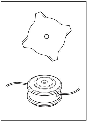
1 grass blade
1 support cup
1 support flange
1 nut
1 box spanner
1 transport guard
NOTE! The trimmer guard must be replaced with the accompanying combination guard if a grass blade is fitted to the machine.

WARNING!
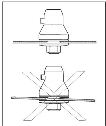
Saw blades must not be fitted on a machine equipped with a J-handle.
List of contents
CONTENTS
Components in the J-handle set 2
List of contents 2
SAFETY INSTRUCTIONS
Cutting equipment 3
Basic clearing techniques 4
ASSEMBLY
Assembling the J-handle 5
Fitting the suspension ring. 5
Assembly of the blade and trimmer head. 5
Fitting the combination guard, grass blade and grass knife ... 5
START AND STOP
Control before starting 6
TECHNICAL DATA
Approved accessories J-handle 7
Cutting equipment
This section describes how through correct maintenance and through using the right type of cutting equipment you can:
- Reduce the machine's tendency to kickback
- Obtain maximum cutting capacity.
- Increase the service life of the cutting equipment.
The three basic rules:
1)Only use the cutting and guard equipment we recommend! See chapter "Technical data".
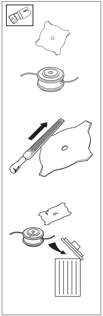
2)Keep the blade's teeth well and correctly sharpened! Follow our instructions and use the recommended filing gauge. An incorrectly sharpened or damaged blade increases the risk of an accident.
3)Check the cutting equipment with regard to damage and crack formation. Damaged cutting equipment should always be replaced.
IMPORTANT INFORMATION
The section describes how through correct maintenance and through using the right type of cutting equipment you can reduce the machine's tendency to kickback, obtain maximum clearing capacity and increase the service life of the cutting equipment.
- Only use the cutting and guard equipment we recommend! See chapter "Technical data".
Refer to the instructions for the cutting equipment for the correct winding of cord and for the selection of the right cord diameter. - Keep the blade's teeth well and correctly sharpened! Follow our recommendations. Also refer to the instructions on the blade packaging.

WARNING!
Incorrect cutting equipment or an incorrectly sharpened blade increases the risk of kickback.
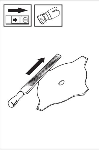
Filing the grass blade
- See the cutting equipment's packaging for correct filing instructions.
- The blades are sharpened using a single cut flat file.
- Sharpen all edges equally to maintain the balance of the blade.
Basic clearing techniques
- Always carry out clearing and trimming at full throttle.
- Always drop to idling speed after each working operation. Longer periods running at full throttle without loading the engine (that is without resistance, which the engine feels from the cutting equipment when trimming) can lead to serious engine damage.
Designations
- Brush cutting is a general term for clearing grass. Grass blades are used for this purpose.
- Grass trimming is a general term for light clearing, e.g. around edges or around trees. A trimmer head or plastic blade is used.

WARNING!
Sometimes grass can collect in the spray guard and cutting head. Always stop the engine when cleaning.
Brush cutting using a grass blade
- A blade is used for all types of high or thick grass.
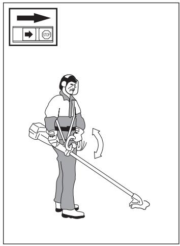
- The grass is cut down with a sideways, swinging movement, where the movement from right-to-left is the clearing stroke and the movement from left-to-right is the return stroke. Let the blade work on the left-hand side (between 8 and 12 o'clock).
- If the blade is angled to the left when clearing the grass will collect in a line, which makes collection easier, e.g. when raking.
- Try to work rhythmically. Stand firmly with your feet apart. Move forward after the return stroke and stand firmly again.
- Let the support cup rest lightly against the ground. It is used to protect the blade from hitting the ground.
- Reduce the risk of material wrapping around the blade by following these instructions:
a) Always work at full throttle.
b) Avoid the previously cut material during the return stroke.
- Stop the engine, loosen the harness and place the machine on the ground before you start to collect the cut material.

WARNING!
Neither the user of the tool or anyone else may attempt to remove the cut material while the engine is running or with the blade rotating as this can result in serious injury.
Stop the engine and blade before you remove material that has wound around the blade as otherwise there is a risk of injury.

WARNING!
Warning for thrown objects. Always wear protective glasses. Never lean over the guard. Stones, rubbish, etc. can be thrown up into the eyes causing blindness or serious injury. Keep unauthorised persons at a distance. Children, animals, onlookers and helpers should be kept outside the safety zone of 15m . Stop the machine immediately if anyone approaches.
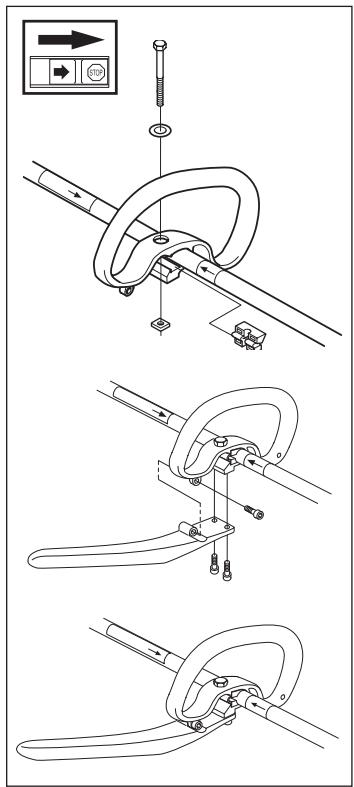
Assembling the J-handle

WARNING
Only grass blades or trimmer heads/ plastic blades may be used when the J-handle is fitted. Clearing blades must never be used with the J-handle.
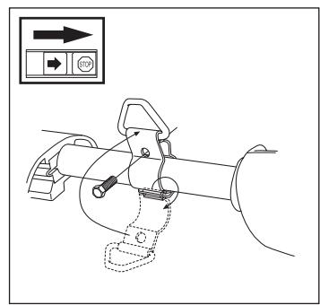
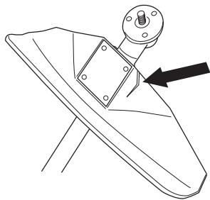
- Clip the loop handle onto the shaft. Note that the loop handle must be fitted between the arrows on the shaft.
- Slide the spacer into the slot in the loop handle.
- Fit the nut, washer and screw. Do not overtighten.
- Attach the J-handle to the loop handle using the three screws, as shown.
- Now adjust the trimmer to give a comfortable working position. Tighten the screw.
Fitting the suspension ring
Fit the suspension ring between the rear handle and the loop handle. Position the suspension ring so that the machine is balanced and comfortable to work with.
Adjusting the harness
Put on the harness and hang the trimmer in the suspension hook. Now finely adjust so that the trimmer gives a comfortable working position when it's attached to the harness.
Assembly of the blade and trimmer head
It is extremely important that the disc drive's/support flange's guide engages correctly in the cutting equipment's centre hole when assembling the cutting equipment. Cutting equipment assembled incorrectly can result in serious and/or fatal personal injury.

WARNING!
Under no circumstances may the cutting equipment be used without an approved guard fitted. See the chapter "Technical data". If the wrong guard or a defective guard is fitted this can cause serious personal injury.
Do not attach any blade to the unit without proper installation of all required parts. Failure to use the proper parts can cause the blade to fly off and seriously injure the operator and/or bystanders.
Fitting the combination guard, grass blade and grass knife
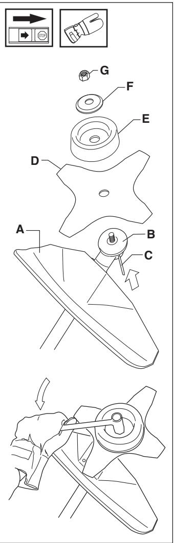
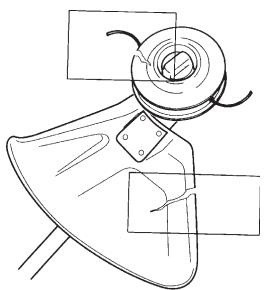
- Hook the guard (A) onto the bracket on the shaft and secure with 1 bolt. NOTE! Use the recommended blade guard. "See Technical data".
- Fit the drive disc (B) on the output axle.
- Turn the blade axle until one of the holes in the drive disc aligns with the hole in the gear housing.
- Insert the locking pin (C) in the hole so that the axle is locked.
- Place the blade (D), support cup (E) and support flange (F) on the output axle.
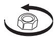
- Fit the nut (G). The tightening torque of the nut is 35 - 50Nm (3,5 - 5 kpm ). Use the socket spanner in the tool kit. Hold the handle of the spanner as close to the blade guard as possible. The nut is tightened when the spanner is turned against the direction of rotation (left-hand thread).
Control before starting
For reasons of safety follow these recommendations!
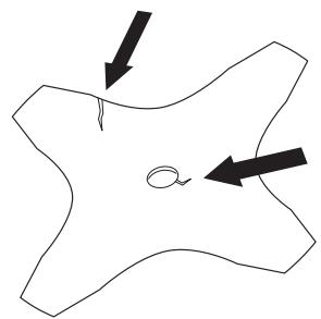
- Check the blade to ensure that no cracks have formed at the bottom of the teeth or by the centre hole. The most common reason why cracks are formed is that sharp corners have been formed at the bottom of the teeth while sharpening or that the blade has been used with dull teeth. Discard a blade if cracks are found.
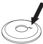
- Check that the support flange is not cracked due to fatigue or due to being tightened too much. Discard the support flange if it is cracked.
- Ensure the locking nut has not lost its captive force. The nut lock should have a locking force of at least 1.5Nm . The tightening torque of the locking nut should be 35 - 50Nm .
- Check that the guard is not damaged or cracked. Replace the guard if it is exposed to impact or is cracked.
- Check that the trimmer head and spray guard are not damaged or cracked. Replace the trimmer head or spray guard if they are exposed to impact or are cracked.
- Never use the machine without a guard or spray guard nor with a defective guard.
| Approved accessories J-handle Centre hole in blades Ø 25,4 mm (1") Threaded blade axle M10 | Type | Cutting attachment guard Art No. |
| Grass blade | Grass 255-4 1" (Ø 255 4-teeth) | 503 93 42-02 |
| Plastic knives | Tricut Ø 300 | 503 93 42-02 |
| Trimmer head | S35 | 503 93 42-02 |
| T35 | 503 93 42-02 | |
| Superauto II 1" | 503 93 42-02 | |
| Trimmy Fix | 503 93 42-02 | |
| Support cup | Fixed | - |