721-489 - Brush cutter Meec Tools - Free user manual and instructions
Find the device manual for free 721-489 Meec Tools in PDF.


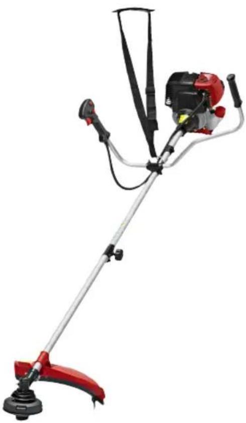
| Product Type | Brush cutter (clearing saw) |
| Brand | Meec Tools |
| Model | 721-489 |
| Engine Type | 4-stroke, air-cooled |
| Engine Displacement | 31 cm³ |
| Engine Power | 0.7 kW |
| Idle Speed | 3100 ± 400 rpm |
| Max Speed (Clearing Blade) | 7000 rpm |
| Max Speed (Trimmer) | 6000 rpm |
| Fuel Tank Capacity | 0.7 L |
| Oil Tank Capacity | 0.08 L |
| Oil Type | 15W40 |
| Cutting Width (Trimmer) | 480 mm |
| Cutting Diameter (Blade) | 255 mm |
| Trimmer Line Diameter | 2.5 mm |
| Weight | 8 kg |
| Sound Pressure Level (LpA) | 94 dB(A), K=3 dB |
| Sound Power Level (LwA) | 113 dB(A), K=3 dB |
| Vibration Level | 7.3 m/s², K=1.5 m/s² |
| Ignition System | TCI |
| Spark Plug | A5RTC, electrode gap 0.6 mm |
| Drive | Centrifugal clutch |
| Safety Features | Harness with quick-release, blade guard, throttle lock, emergency stop switch |
| Maintenance Intervals | Air filter every 25h, spark plug every 50h, gear grease every 20h, oil change as needed |
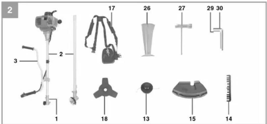
| Included Accessories | Harness, blade guard, trimmer head, clearing blade, combination wrench, hex keys, measuring beaker, spark plug spanner |
Frequently Asked Questions - 721-489 Meec Tools
User questions about 721-489 Meec Tools
0 question about this device. Answer the ones you know or ask your own.
Ask a new question about this device
Download the instructions for your Brush cutter in PDF format for free! Find your manual 721-489 - Meec Tools and take your electronic device back in hand. On this page are published all the documents necessary for the use of your device. 721-489 by Meec Tools.
USER MANUAL 721-489 Meec Tools
natural_image
Red and black manual tool with metal arm and tripod blade (no visible text or symbols)EN Operating instructions for clearing saw
SE - Bruksanvisning i original
EN - Operating instructions (Translation of the original instructions)
Jula reserves the right to make changes. In the event of problems, please contact our service department.
www.jula.com
Tillverkare/ Produsent / Produenci/ Manufacturer
Jula AB, Box 363, 532 24 SKARA
Importör/ Importør/ Importer/ Importer
Care for the environment!
Must not be discarded with household waste! This product contains electrical or electronic components that should be recycled. Leave the product for recycling at the designated station e.g. the local authority's recycling station.
SVENSKA....5
SÄKERHETSANVISNINGAR....5
TEKNISKA DATA....13
BESKRIVNING 14
ILLUSTRATIONER....16
MONTERING 20
HANDHAVANDE 21
UNDERHÅLL 24
FELSÖKNING....27
NORSK 28
SIKKERHETSANVISNINGER 28
TEKNISKE DATA 36
BESKRIVELSE....37
ILLUSTRASJONER....39
MONTERING 43
BRUK 44
VEDLIKEHOLD 47
FEILS∅KING....50
POLSKI 51
ZASADY BEZPIECZEŃSTWA 51
DANE TECHNICZNE 59
OPIS 60
ILUSTRACJE 62
MONTAŻ 66
OBSŁUGA 67
KONSERWACJA 70
WYKRYWANIE USTEREK 74
ENGLISH 75
SAFETY INSTRUCTIONS....75
TECHNICAL DATA 83
DESCRIPTION 84
ILLUSTRATIONS 86
ASSEMBLY....90
USE....91
MAINTENANCE 94
TROUBLESHOOTING 97
SÄKERHETSANVISNINGAR
natural_image
Close-up of a hand holding a metal tool with a curved blade and a circular base, labeled '15' and '5b' (no text or symbols on the tool itself)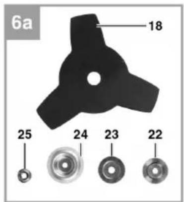
natural_image
Mechanical assembly diagram showing a component labeled '22' and part identifier '6b' (no readable text or symbols beyond labels)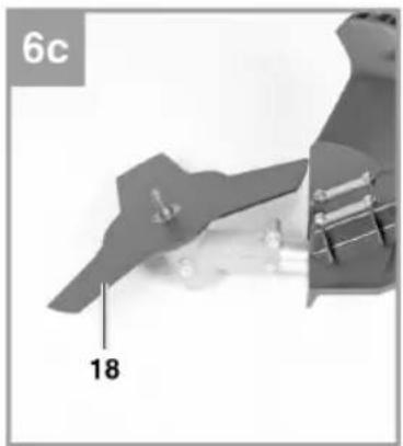
natural_image
Close-up of a mechanical component with labeled part '18' and page number '6c' (no readable text or symbols beyond labels)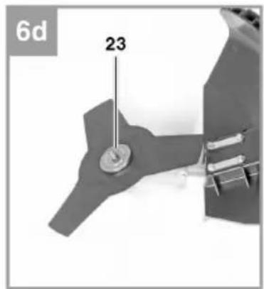
natural_image
Close-up of a mechanical component with labeled parts (24 and 6e), no readable text or symbols beyond labels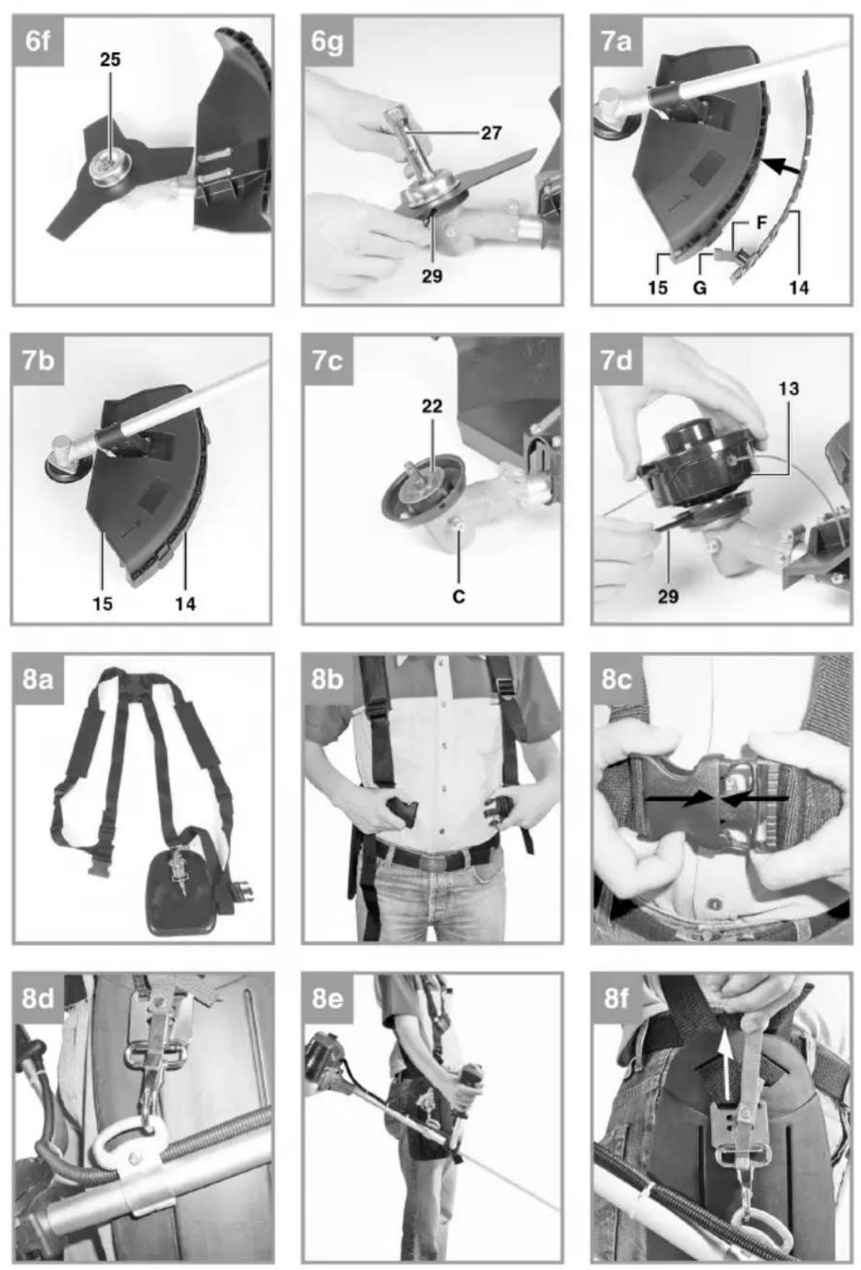
natural_image
Illustration of two firefighters spraying water on a grassy field (no text or symbols)
natural_image
Diagram of a person operating a large mechanical device with a downward arrow, labeled '9b' in the top-left corner (no other text or symbols)
natural_image
Simple line drawing of a mechanical device with lever and base, no text or symbols present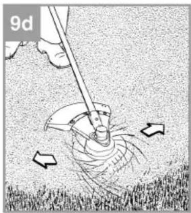
natural_image
Illustration of a person using a manual tool to lift grass, with arrows indicating motion (no text or symbols)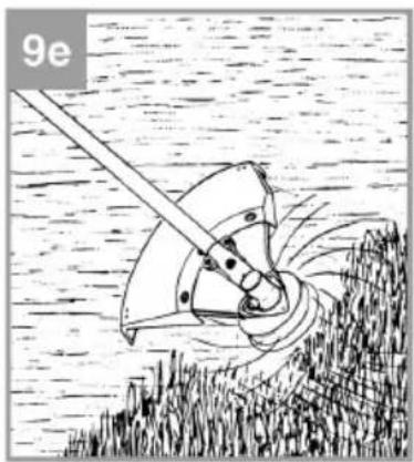
natural_image
Illustration of a mechanical device with rotating components, set against a textured background (no text or symbols)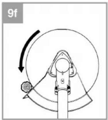
natural_image
Mechanical diagram showing a rotating component with a curved arrow indicating rotational motion (no text or symbols)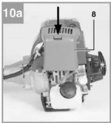
natural_image
Mechanical device with labeled parts, no visible text or symbols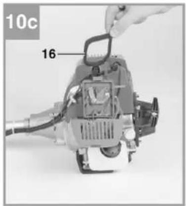
natural_image
Close-up of a mechanical device with a rotary knob and clamped components (no visible text or symbols)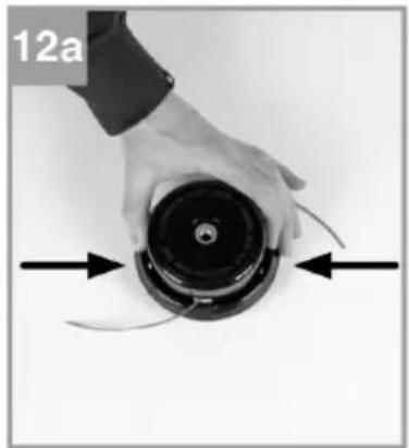
natural_image
Close-up of a hand holding a black circular device with curved arrows indicating motion or force (no text or symbols visible)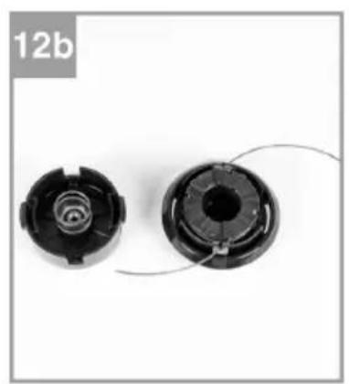
natural_image
Two black plastic mechanical components with spiral and threaded ends, shown against a white background (no text or symbols)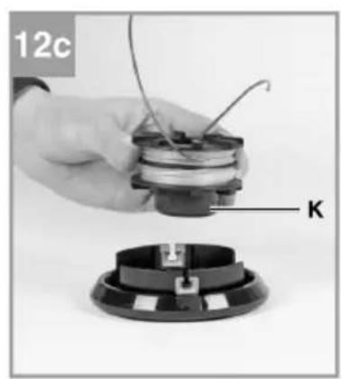
natural_image
Close-up of a hand holding a small electronic component with wires, next to a circular base labeled 'K' (no text or symbols on the device itself)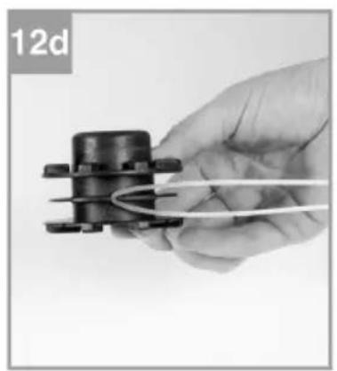
natural_image
Hand holding a small mechanical component with coiled wires, labeled '12d' in top-left corner (no other text or symbols)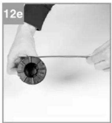
natural_image
Close-up of hands holding a spool of black film reel with a string (no text or symbols visible)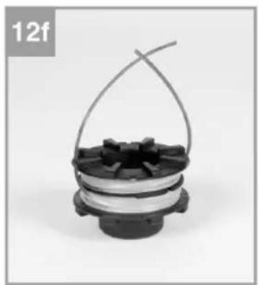
natural_image
Close-up of a mechanical component with a coiled spring and spool, labeled '12f' in the top-left corner (no other text or symbols visible)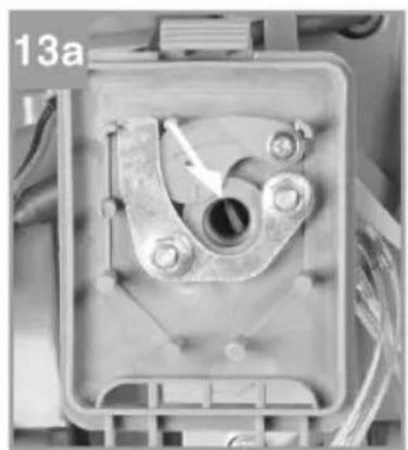
natural_image
Close-up of a mechanical component with a central hole and bolts, no visible text or symbols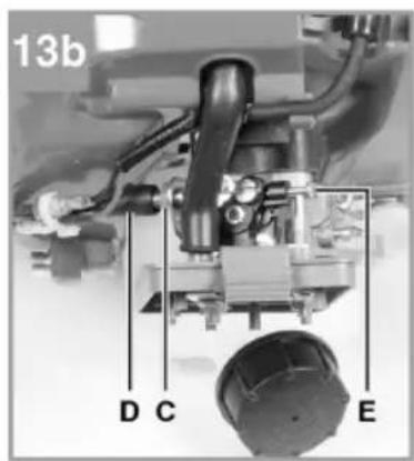
natural_image
Mechanical device with labeled parts, no visible text or symbols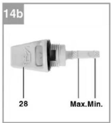
MONTERING
Leveransomfattning
natural_image
Close-up of a hand holding a pen-like tool with a mechanical component, labeled '5b' and '15' (no readable text or symbols beyond labels)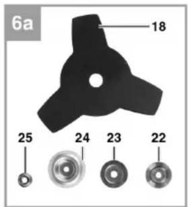
natural_image
Mechanical assembly diagram showing a component labeled '22' and part identifier '6b' (no readable text or symbols beyond labels)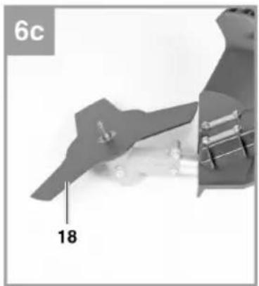
natural_image
Close-up of a mechanical component with labeled part '18' and page number '6c' (no readable text or symbols beyond labels)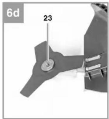
natural_image
Close-up of a mechanical component with a numbered annotation '24' and part number '6e' (no readable text or symbols beyond labels)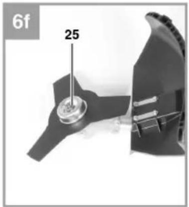
natural_image
Close-up of a mechanical component with a numbered part (25) and a separate view showing internal structure (no text or symbols)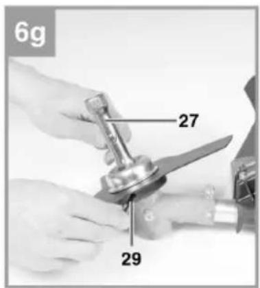
natural_image
Close-up of a mechanical device with labeled parts (14 and 15), no readable text or symbols beyond labels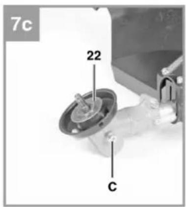
natural_image
Black and white photo of a black athletic harness with straps and a small bag (no text or symbols visible)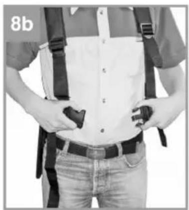
natural_image
Person wearing a vest with straps and hands, standing in front of shirt (no visible text or symbols)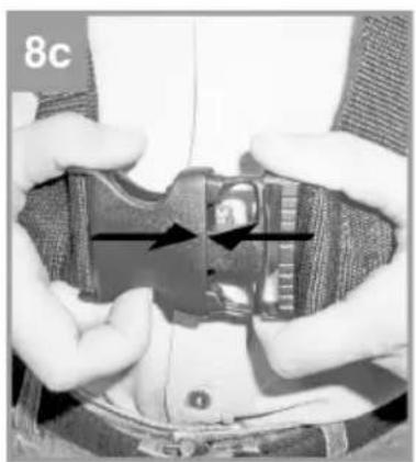
natural_image
Close-up of hands holding a small electronic device with a lock, showing internal components and arrows indicating motion (no text or symbols visible)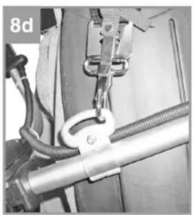
natural_image
Close-up of a mechanical assembly with hoses and a coiled spring (no visible text or symbols)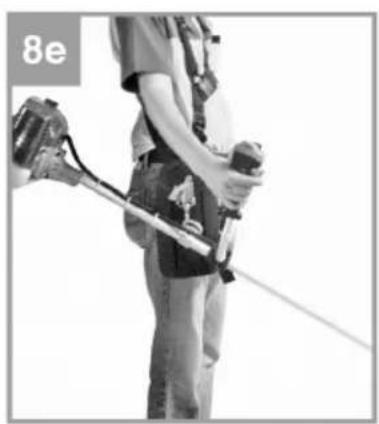
natural_image
Person wearing safety harness and holding a tool, standing with one arm extended (no visible text or symbols)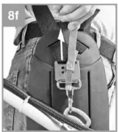
natural_image
Person wearing a harness and safety belt, holding a cable with a loop (no visible text or symbols)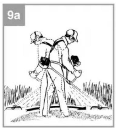
natural_image
Illustration of a person spraying water onto a field with two children (no text or symbols)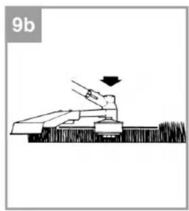
natural_image
Diagram of a mechanical device with a downward arrow indicating motion or force, labeled '9b' in the top-left corner (no other text or symbols)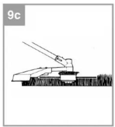
natural_image
Simple line drawing of a crane lifting a block, no text or symbols present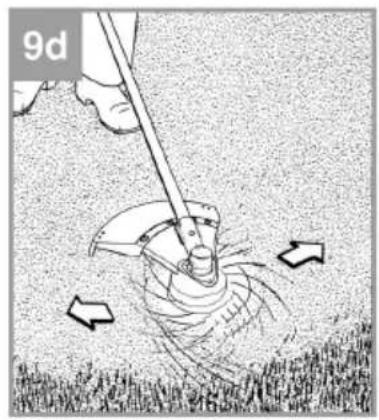
natural_image
Illustration of a hand using a tool to lift a person's arm, with arrows indicating motion (no text or symbols)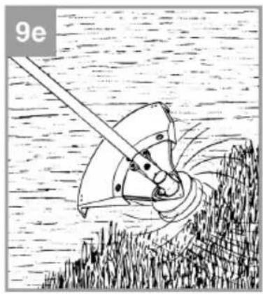
natural_image
Illustration of a mechanical device with rotating blades and a handle, resting on a textured surface (no text or symbols)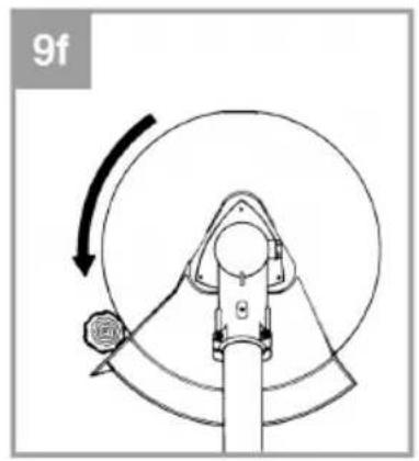
natural_image
Diagram of a mechanical device with a rotating wheel and lever mechanism (no text or symbols)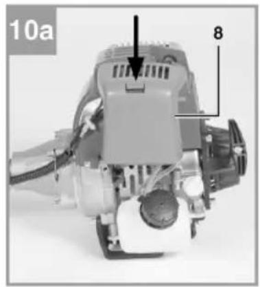
natural_image
Mechanical assembly component with labeled parts (8 and 10b), no readable text or symbols beyond labels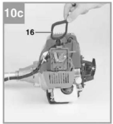
natural_image
Close-up of a mechanical device with a hand operating it, showing internal components and a rotation arrow (no text or symbols visible)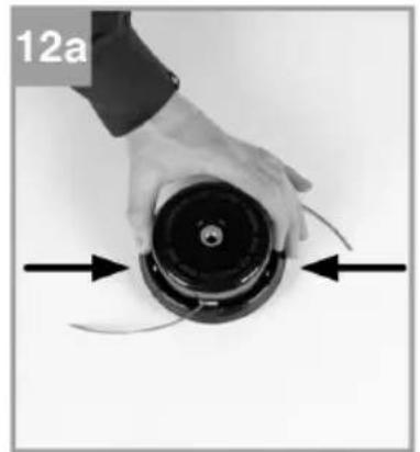
natural_image
Close-up of a hand holding a black circular device with curved arrows indicating motion or force direction (no text or symbols)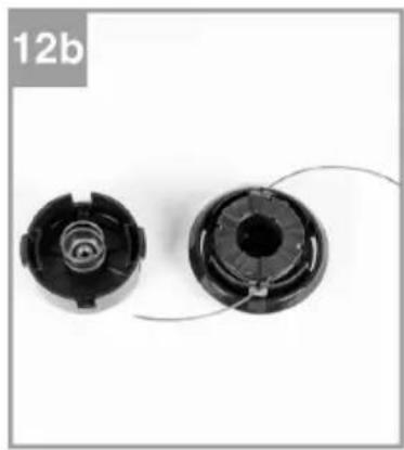
natural_image
Two black plastic mechanical components with circular features, shown from different angles (no text or symbols visible)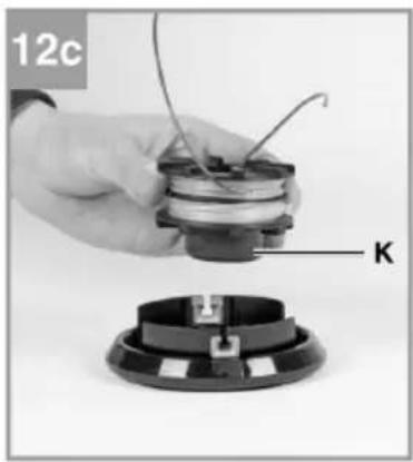
natural_image
Close-up of a hand holding a small electronic component with wires, next to a circular base labeled 'K' (no text or symbols on the device itself)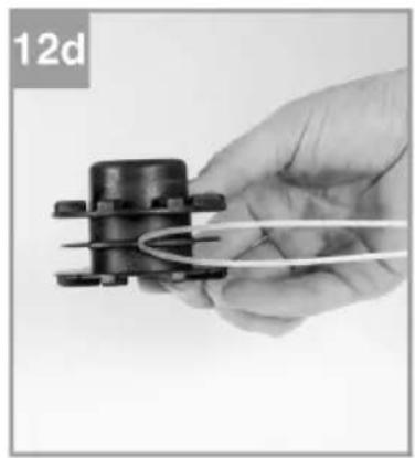
natural_image
Hand holding a mechanical component with a coiled cable, labeled '12d' in the corner (no other text or symbols visible)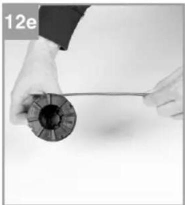
natural_image
Close-up of hands holding a cylindrical object with a string, no visible text or symbols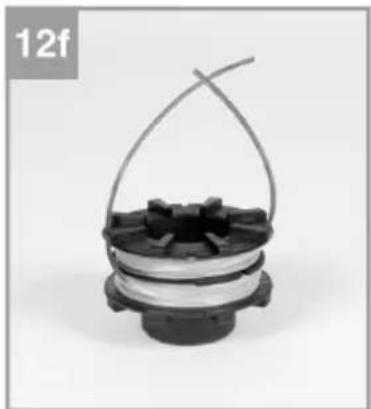
natural_image
Close-up of a mechanical component with a coiled spring and spool, labeled '12f' in the top-left corner (no other text or symbols visible)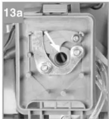
natural_image
Close-up of a mechanical component with a central hole and mounting holes, no visible text or symbols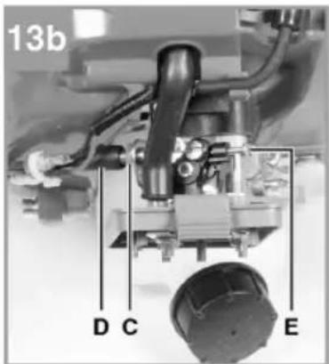
natural_image
Close-up of a mechanical device with labeled parts (14a and 28), no readable text or symbols beyond labels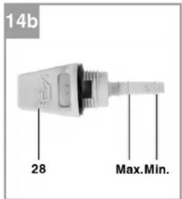
MONTERING
Leveransens omfang
Stille inn tomgangsgass
Still inn tomgangsgass mens maskinen er driftsvarm. Turtallet når verktøyet starter, skal gå opp til minst 1,25 ganger tomgangsturtallet. OBS! Tomgangsgass må kun innstilles av et autorisert serviceverksted.
Smør girene
natural_image
Close-up of a hand holding a metal tool with a curved arrow indicating rotation, next to a small mechanical component labeled '15' (no text or symbols on the tool itself)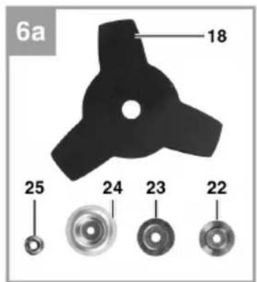
natural_image
Mechanical assembly diagram showing a component labeled '22' and part identifier '6b' (no readable text or symbols beyond labels)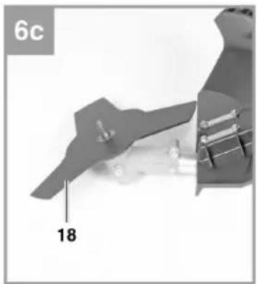
natural_image
Close-up of a mechanical component with labeled part '18' and page number '6c' (no readable text or symbols beyond labels)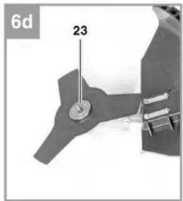
natural_image
Close-up of a mechanical component with labeled parts (24 and 6e), no readable text or symbols beyond labels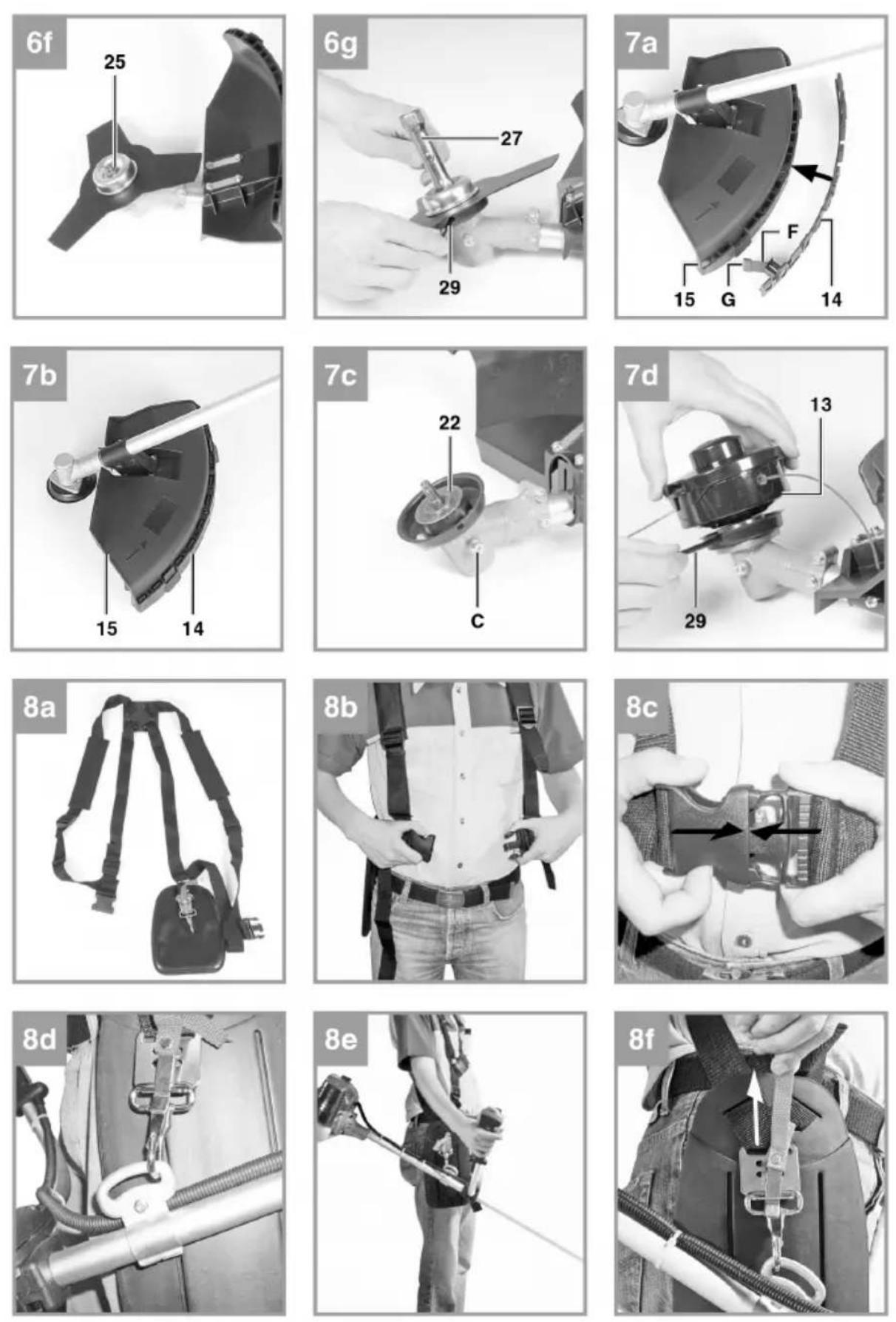
natural_image
Illustration of two firefighters spraying water on a grassy field (no text or symbols)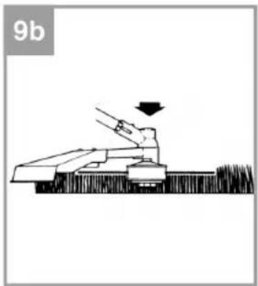
natural_image
Diagram of a person operating a large mechanical device with a downward arrow, labeled '9b' in the top-left corner (no other text or symbols)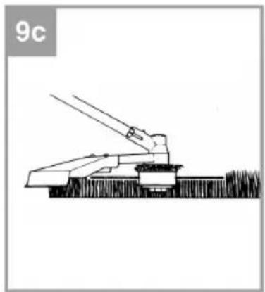
natural_image
Simple line drawing of a mechanical device with lever and base, no text or symbols present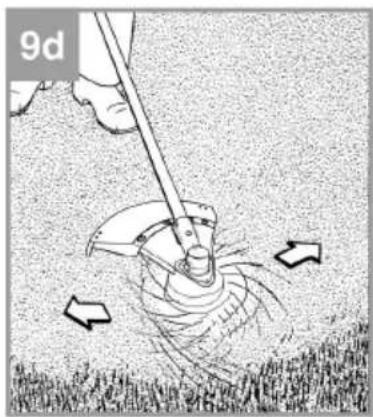
natural_image
Illustration of a person using a manual tool to lift grass, with arrows indicating motion (no text or symbols)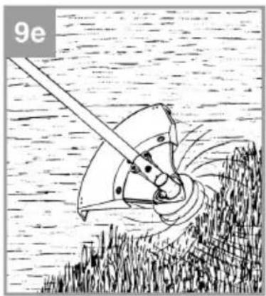
natural_image
Illustration of a mechanical device with rotating components and a lever, set against a textured background (no text or symbols)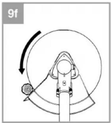
natural_image
Mechanical diagram showing a rotating component with a curved arrow indicating rotational motion (no text or symbols)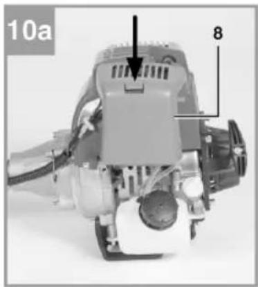
natural_image
Mechanical device with labeled parts, no visible text or symbols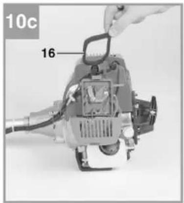
natural_image
Close-up of a mechanical device with a rotary knob and clamped components (no visible text or symbols)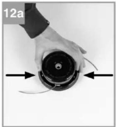
natural_image
Close-up of a hand holding a black circular device with directional arrows indicating motion or force (no text or symbols)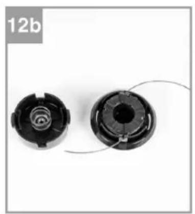
natural_image
Two black plastic mechanical components with spiral and threaded ends, shown against a white background (no text or symbols)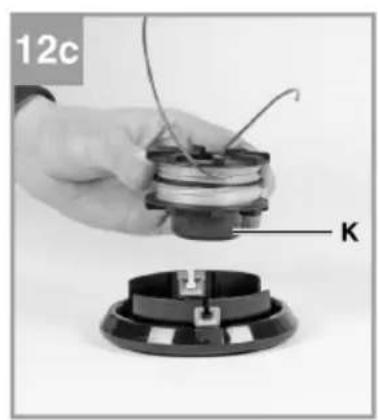
natural_image
Close-up of a hand holding a small electronic component with wires, labeled 'K' (no text or symbols on the device itself)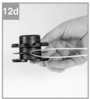
natural_image
Hand holding a small mechanical component with coiled wires, labeled '12d' in top-left corner (no other text or symbols)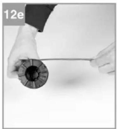
natural_image
Close-up of hands holding a spool of black film reel with a string (no text or symbols visible)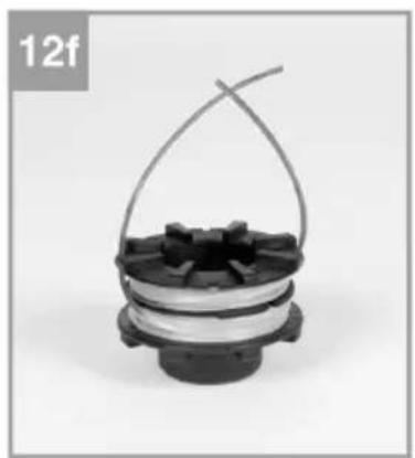
natural_image
Close-up of a mechanical component with a coiled spring and spool, labeled '12f' in the top-left corner (no other text or symbols visible)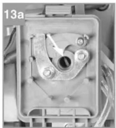
natural_image
Close-up of a mechanical component with a central hole and bolts, no visible text or symbols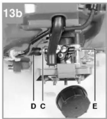
natural_image
Mechanical device with labeled parts, no visible text or symbols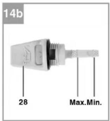
MONTAŽ
Kontrola dostawy
Read the operating instructions carefully before use.
Save them for future reference.
- Check that the cutting tool does not rotate when the engine is idling. If the tool rotates when idling, stop working and contact your dealer.
- Read all the instructions and safety instructions before use. Failure to follow all the instructions and safety instructions can result in the risk of electric shock, fire and/or serious personal injury.
- Never allow children, or anyone who is unfamiliar with the machine and these instructions, to use it.
- Never start or run the engine in enclosed or poorly ventilated areas – inhalation of exhaust fumes is harmful and can result in unconsciousness and fatal injury.
- Check that there are no people, animals or other obstacles in the work area. Remove any objects that can fasten in, or be thrown out, by the machine.
- Wear safety glasses.
- Wear heavy-duty, tight-fitting long trousers, safety shoes and safety gloves. Do not wear loose-fitting clothes or shorts, and do not work barefoot. Do not wear jewellery.
• Always keep the machine on your right side. - Wear a hair net if you have long hair to prevent your hair fastening in moving parts.
- Keep people and animals at least 15 metres away from the work area.
- Never use the machine when you are tired, ill, or under the influence of drugs, alcohol or medication.
- Only use the machine in daylight, or in good artificial lighting.
- Always maintain a firm footing and good balance. Do not overreach – this can cause you to lose your balance or touch hot parts of the machine.
- Keep your hands and the rest of your body away from the moving parts on the machine.
- To reduce the risk of touching hot parts, never work with the top edge of the engine above hip height.
-
Do not touch the exhaust system or cylinder while working with the machine – risk of burn injuries.
-
Switch off the engine and remove the spark plug lead before adjustments or repairs, except when adjusting the carburettor.
- Always check the machine before using it for loose parts, fuel leakage and damage etc. Damaged parts must be replaced before the machine is used.
- The trimmer head/clearing blade rotates when adjusting the carburettor and when starting the engine.
- Prolonged exposure to vibration can cause numbness in hands and arms, or more severe neurovascular complaint, white fingers (Raynaud's syndrome), or carpal tunnel syndrome. The risk of developing such problems also depends on hereditary disposition, exposure to cold and damp, diet, smoking and work experience. The relationship between exposure to vibration and symptoms is still not fully understood. Some of the measures users can take to reduce the risk of problems and injuries associated with exposure to vibration are described below. Coldness is a known risk factor for white fingers:
— Dress properly for the weather and wear gloves that keep your hands and wrists warm.
- Move about to maintain your blood circulation.
— Take regular pauses in the work and limit the total time spent working per day.
- Keep the machine in good condition – tighten loose parts and fasteners, and replace worn parts.
- Stop working immediately and seek medical attention if you experience numbness, itching, tingling or pain, or if your skin changes colour.
- Handle and store the fuel only in containers intended for petrol.
- Handle and fill up with fuel outdoors and at a safe distance from sparks and naked flames. Wipe up any spilled fuel. Move at least 10 m from the place where you fill up with fuel before starting the engine.
- Switch off the engine and allow it to cool before filling up with new fuel, or putting the machine away.
- Pay attention when moving the machine to reduce the risk of dropping it, turning it up upside down, leaking fuel, or causing personal injury or damage.
- Before transporting the machine in a car or other vehicle allow the engine to cool, empty the fuel tank, and secure the machine so that it cannot slip or drop etc.
- If any foreign object fastens in the trimmer head or clearing blade, switch off the engine immediately and wait until all parts have completely stopped. Remove the spark plug lead from the plug and then remove the object/blockage.
- Check the machine and the trimmer head/clearing blade for damage before resuming the work. If the machine is visibly damaged take it to your dealer to be repaired with original parts, or parts recommended by the manufacturer, before using it again.
- Otherwise carefully test the machine. If the machine vibrates excessively or makes abnormal noise, switch off immediately and take it to your dealer to be repaired with original parts, or parts recommended by the manufacturer, before using it again.
Remaining risks
- The machine works with rotating cutting tools. This means there is a risk of material and objects (stones etc.) being thrown up – risk of personal injury.
- Despite the safety devices and the use of personal safety equipment there is a risk of injury as a result of contact with the unprotected parts of the blade or trimmer line.
-
WARNING: Vibration levels during usage can deviate from the declared values, depending on how the machine is used. The following factors affect the vibration level:
-
Incorrect use.
– Working with unsuitable materials. -
Inadequate maintenance.
– Unsuitable accessories.
– The attachment of the handle. -
Stop working immediately and seek medical attention if you experience numbness, itching, tingling or pain, or if your skin changes colour.
- It is incumbent on the user to assess any risks. Make an assessment of the strain involved on the basis of the type of work and the use of the machine, and plan suitable pauses. This can significantly reduce the strain during the time you are working. Minimise the risks you are exposed to from vibrations. Maintain the machine in accordance with these instructions.
- If the tool is used often and/or for long sessions, you should fit it with a vibration-damping handle.
- Do not use the machine in ambient temperatures less than 10^ C. Establish a work plan that contributes to limiting exposure to vibrations.
Special safety instructions when using the trimmer head
- Replace the trimmer head if it is cracked, or otherwise damaged. Carefully check that you have fitted the new trimmer correctly. An incorrectly fitted or inadequately tightened trimmer head can result in serious personal injury.
- Check that all the guards and handles are correctly and firmly fitted.
- Only use trimmer lines and accessories recommended by the manufacturer.
- The use of accessories not recommended by the manufacturer can result in serious personal injury.
- Do not use the machine unless the guard is fitted and in good condition.
- Keep a firm grip on the machine with both hands when in use. Keep the trimmer head below hip height. Do not work with the trimmer head more than 75 cm above the ground.
Special safety instructions when using the clearing blade
- When you have switched off the engine, stop the rotating clearing blade by holding it against thick weeds or wet stalks.
- Do not use the clearing saw unless the guard is fitted correctly and is in good condition.
- Wear heavy-duty gloves when using the machine and when fitting or removing the clearing blade.
- When fitting or removing the clearing blade, and when removing foreign objects that have fastened or are blocking the clearing blade, always switch off the engine and remove the spark plug lead from the plug.
- Never attempt to touch the clearing blade when it is rotating.
- The clearing blade continues to rotate after the engine is switched off and when the throttle is released. Remain standing in a normal working position with a firm grip on the handles until the clearing blade has completely stopped.
- Always check after use that the clearing blade is undamaged and is correctly and firmly fitted. Replace the clearing blade if it is damaged. A damaged or incorrectly fitted clearing blade can result in serious personal injury.
- Only use clearing blades recommended by the manufacturer and intended for clearing saws. Non-recommended clearing blades can result in serious personal injury.
- When used as a clearing saw with a clearing blade the machine is intended to be used for thick weeds, high and wet grass, and brushwood with a diameter of up to 13 mm. Never use the machine for any other purposes.
- Always be very careful when using the machine with the clearing blade fitted. If the rotating clearing blade hits an object it cannot cut through or throw up this obstructs the rotation of the blade causing the blade and the whole clearing saw to kick back from the object. Kick-back can be very sudden and without warning when the blade encounters an obstacle or jams, and it can be so powerful that you could lose control of the clearing saw. There is a greater risk of kick-back when working in situations where it is difficult to see exactly what the material contains. It is easier and safer to work from left to right. Kick-back resulting from the blade hitting an obstacle will be not be as severe.
- Never attempt to clear material thicker than 13 mm.
- Always use the harness strap when using the machine as a clearing saw, and adjust it so that it fits firmly and comfortably. Hold the machine with both hands in a firm grip when using it. Keep your hands and the rest of your body away from the clearing blade and always keep the blade below hip height.
- Do not work with the clearing blade more than 75 cm above the ground.
- If the machine has a centrifugal clutch, check at regular intervals that the blade stops rotating when the engine is idling.
- WARNING: Watch out for the risk of kick-back when using the machine as a clearing saw.
- Pay attention to the risk of fire and ensure there is good ventilation – keep the engine at least 1 metre from other equipment, buildings and installations when working. Do not place any flammable objects near the engine.
- Keep unauthorised persons, children and pets, away from the workplace.
- Make sure that in risk or emergency situations you can quickly stop the engine and that you understand and know how to use the controls on the machine.
Fuel
- Petrol is highly flammable and in some situations explosive.
- Handle and fill up with fuel outdoors or in a well ventilated area, with the engine switched off and at a safe distance from sparks and naked flames. Never store fuel where there can be naked flames, e.g. smoking or sparks.
- Do not overfill the fuel tank. Check after filling that the filler cap is properly fitted.
- Avoid spilling fuel. Spilled fuel and fumes from spilled fuel can easily ignite. Wipe up any spilled fuel before starting the engine.
Other safety instructions
- The exhaust fumes from the engine are very hot and the exhaust system remains hot after the engine is switched off. Always allow the engine and the exhaust system to cool before putting the machine away indoors, to reduce the risk of fire and burns.
- Take regular breaks when working. Always maintain a firm footing and good balance.
- Wear approved safety shoes with non-slip soles and comfortable fit, tight-fitting clothes, safety glasses, ear protection, safety helmet and vibration-damping gloves.
- When working with the machine keep other people away from the risk zone, i.e. at least 15 metres away. Wear safety glasses, ear protection, safety helmet, safety shoes, leg guards, and if necessary full body protection. Persons immediately outside the risk zone should wear safety glasses and suitable protection from flying objects. The risk diminishes the further you are away from the clearing saw.
IMPORTANT:
- When working with a trimmer or clearing saw there is always a risk that small stones, pieces of metal, small objects and the cleared material can be thrown up.
- Familiarise yourself with the controls on the machine and how to use them. Check that you can quickly switch off the engine. Check that you can quickly open and release the harness strap.
- Never allow children, or anyone who is unfamiliar with the machine and these instructions, to use it. Keep children under supervision to make sure they do not play with the machine. Always wear safety shoes, leg guards, safety glasses, face mask and ear protection when using the machine. Do not rely on the guard to provide adequate protection from objects thrown up directly from the blade, or bouncing back from walls, etc. Keep unauthorised persons, children and pets, away from the workplace. When working with the machine you are in the centre of a risk zone 15 metres in diameter. No persons must enter this risk zone. Persons immediately outside the risk zone should wear safety glasses and suitable protection from flying objects. If you need to use the machine in areas where there are persons without safety equipment, work with reduced throttle to reduce the risk of thrown up objects causing personal injury.
- Check the ignition switch before use – allow the engine to idle, put the switch in the stop position and check that the engine switches off. Do not use the machine if the engine does not switch off. Check at regular intervals that the blade or trimmer head stops when the engine is idling.
WARNING:
- When working on slippery surfaces wear safety shoes with non-slip soles in addition to safety glasses, face guard, ear protection and a safety helmet. Do not wear jewellery, loose-fitting clothes, ties or scarves, or other loose garments that can fasten and be pulled into the machine. Do not wear open shoes or sandals, and do not work barefoot or with bare legs. In some situations it is necessary to wear a full-face mask. Watch out for the risk of kick-back.
Symbols
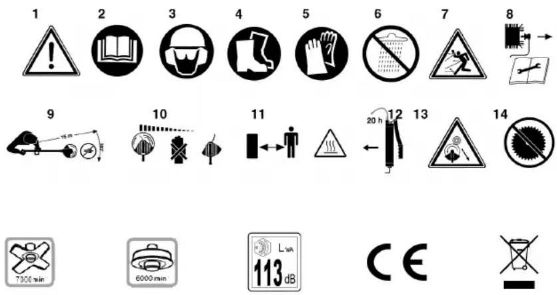
1516171819
- WARNING:
- Read the instructions before use.
- Wear head, eye and ear protection.
- Wear safety shoes.
- Wear safety gloves.
- Protect the machine from rain and moisture.
- Watch out for flying objects.
-
Switch off the machine and release the spark plug lead before maintenance.
-
Keep a distance of at least 15 metres between the machine and persons nearby.
- The tool continues to rotate.
- WARNING: Hot parts. Keep at a safe distance.
- Add a little grease after 20 hours of operation (liquid gear grease).
- Warning for kick-back.
- Do not use saw blades.
- The max speed for clearing blade is 7000 rpm.
- The max speed for trimmer head is 6000 rpm.
- The sound power level is LwA113 dB.
- Approved as per applicable directives.
- Recycle discarded product.
TECHNICAL DATA
| Engine type Air cooled four-stroke engine | |
| Engine capacity 0.7 kW | |
| Displacement 31 cm3 | |
| Idling speed 3100 ± 400 rpm | |
| Max speed Clearing saw: 7000 rpm | |
| Trimmer: 6000 rpm | |
| Ignition system TCI | |
| Spark plug A5RTC | |
| Electrode gap 0.6 mm | |
| Drive Centrifugal clutch | |
| Trimmer line ∅ 2.5 mm | |
| Cutting width ∅ 480 mm | |
| Clearing blade ∅ 255 mm | |
| Fuel tank volume | 0.7 l |
| Engine oil 15W40 | |
| Oil tank volume | 0.08 l |
| Weight | 8 kg |
| Sound pressure level, LpA | 94 dB(A), K=3 dB |
| Sound power level, LwA | 113 dB(A), K=3 dB |
| Vibration | 7.3 m/s2, K=1.5 m/s2 |
Always wear ear protection.
The declared vibration value, which has been measured by a standardised test method, can be used to compare different tools with each other and for a preliminary assessment of exposure.
WARNING: The actual vibration level when using power tools may differ from the specified maximum value, depending on how the tool is used. It is therefore necessary to determine which safety precautions are required to protect the user, based on an estimate of exposure in actual operating conditions (taking into account all stages of the work cycle, e.g. the time when the tool is switched off and when it is idling, in addition to the start-up time).
DESCRIPTION
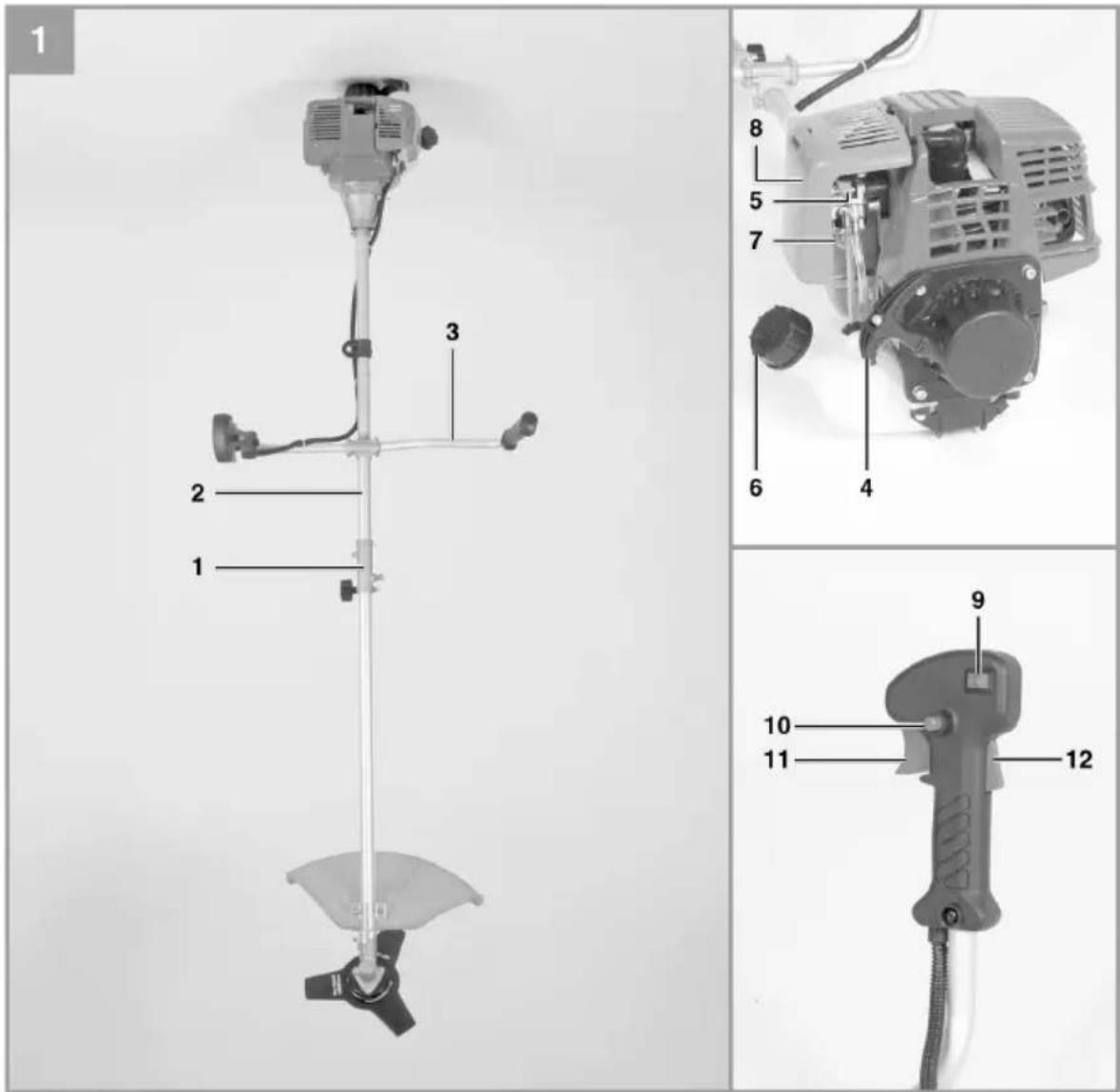
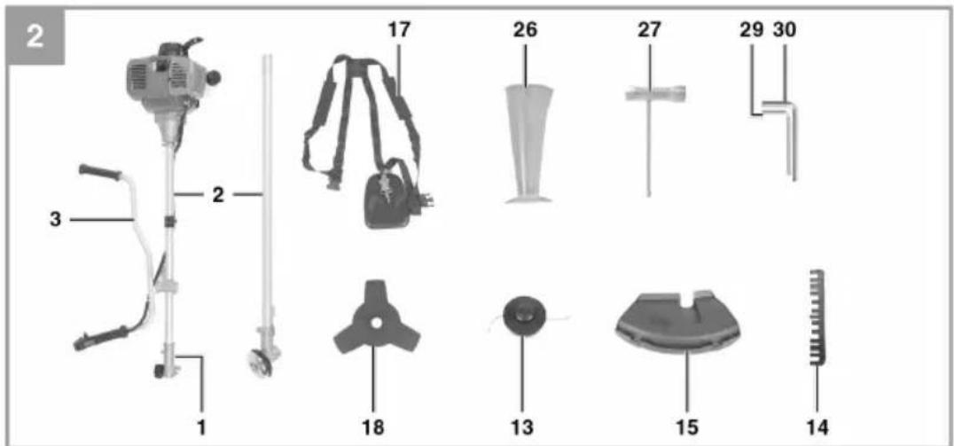
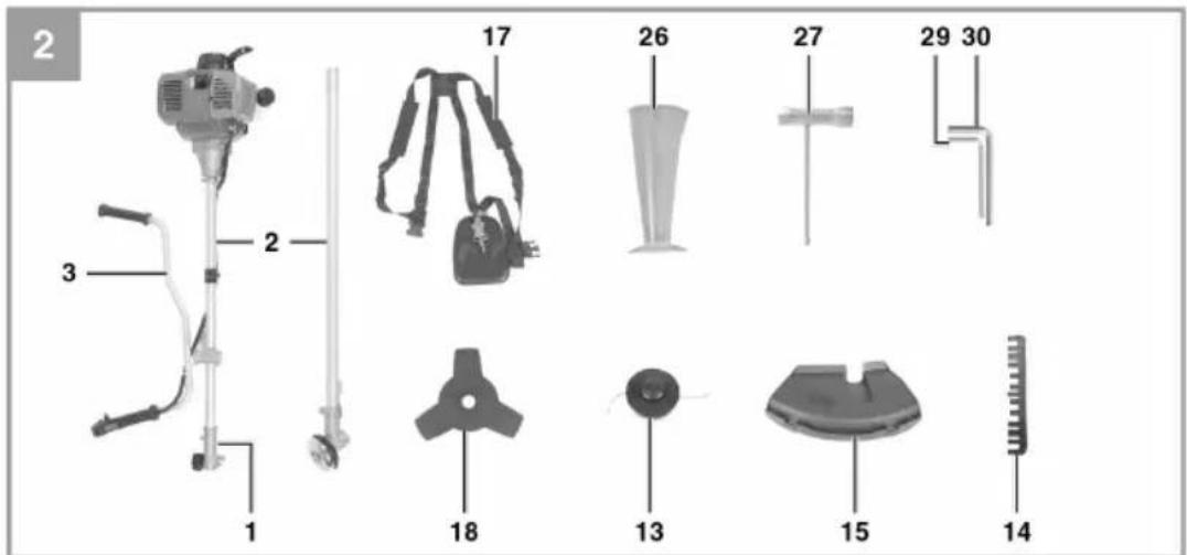
- Shaft coupling
- Shaft
- Handlebar
- Starter cord
- Choke
- Petrol tank
- Fuel pump (primer)
- Cap for air filter
- Power switch
- Lock for throttle control
- Throttle control
- Throttle lock
- Trimmer head
- Guard for trimmer line
-
Guard for clearing blade
-
Air filter
- Harness
- Clearing blade
- Holder for handlebar
- Spark plug lead
- Star knob M6
- Carrier plate
- Pressure plate
- Cover for pressure plate
- Nut M10 (left-hand thread)
- Measuring beaker
- Spark plug spanner
- Oil filler plug
- Hex key 4 mm
- Hex key 5 mm
ILLUSTRATIONS
natural_image
Close-up of a hand holding a metal tool with a curved arrow indicating rotation, next to a mechanical component labeled '15' (no text or symbols on the tool itself)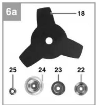
natural_image
Mechanical assembly diagram showing a component labeled '22' and part identifier '6b' (no readable text or symbols beyond labels)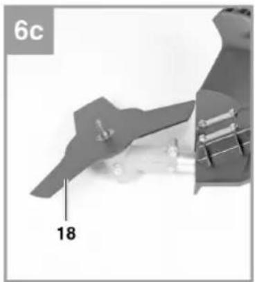
natural_image
Close-up of a mechanical component with labeled part '18' and page number '6c' (no readable text or symbols beyond labels)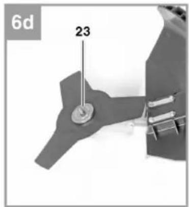
natural_image
Close-up of a mechanical component with labeled parts (24 and 6e), no readable text or symbols beyond labels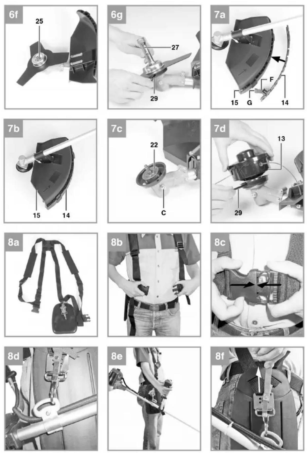
natural_image
Illustration of two firefighters spraying water on a grassy field (no text or symbols)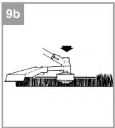
natural_image
Diagram of a person operating a large mechanical device with a downward arrow, labeled '9b' in the top-left corner (no other text or symbols)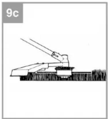
natural_image
Simple line drawing of a mechanical device with lever and base, no text or symbols present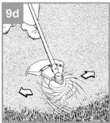
natural_image
Illustration of a person using a manual tool to lift grass, with arrows indicating motion (no text or symbols)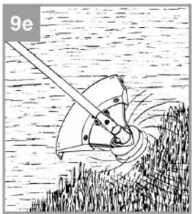
natural_image
Illustration of a mechanical device with rotating components, set against a textured background (no text or symbols)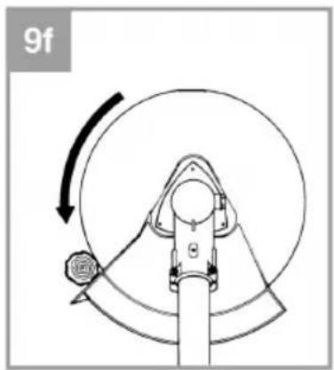
natural_image
Mechanical diagram showing a rotating wheel and lever mechanism (no text or symbols)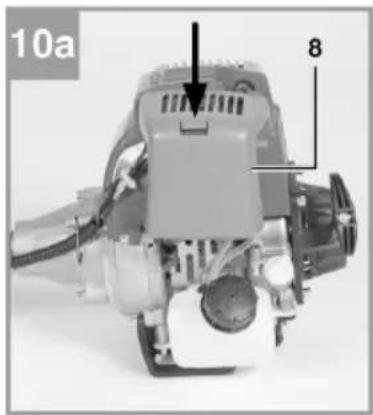
natural_image
Mechanical device with labeled parts, no visible text or symbols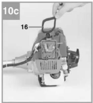
natural_image
Close-up of a mechanical device with a rotary knob and clamped components (no visible text or symbols)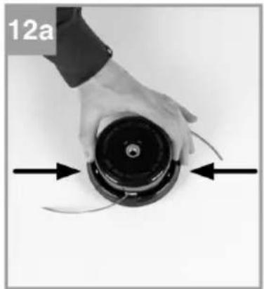
natural_image
Close-up of a hand holding a black circular device with curved arrows indicating motion or force (no text or symbols visible)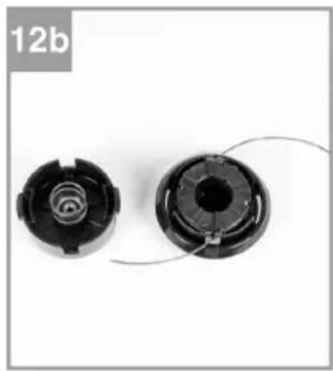
natural_image
Two black plastic mechanical components with internal threading and a coiled wire, labeled '12b' in the top-left corner (no other text or symbols)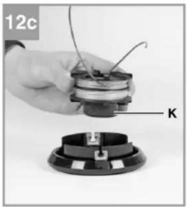
natural_image
Close-up of a hand holding a small electronic component with wires, next to a black circular base labeled 'K' (no text or symbols on the device itself)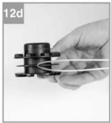
natural_image
Hand holding a small mechanical component with a coiled wire, labeled '12d' in the corner (no other text or symbols visible)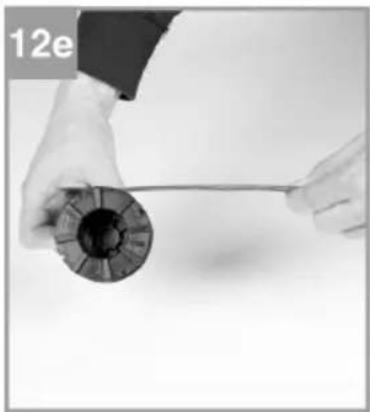
natural_image
Close-up of hands holding a cylindrical object with a string, no visible text or symbols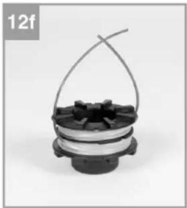
natural_image
Close-up of a black-and-white mechanical component with a curved wire loop, no visible text or symbols.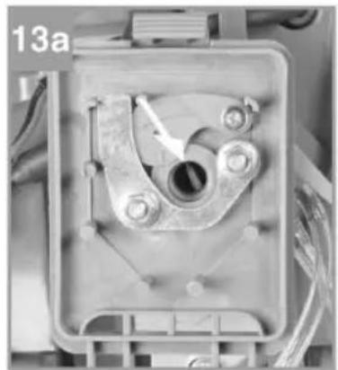
natural_image
Close-up of a mechanical component with a central hole and bolted base, no visible text or symbols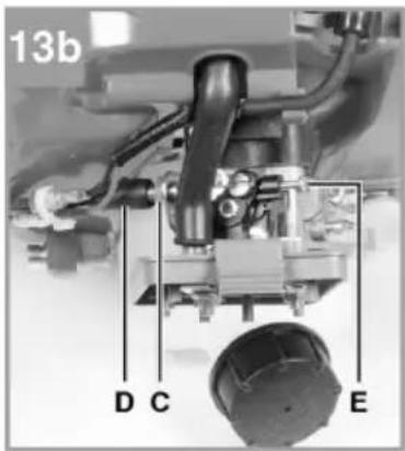
natural_image
Mechanical device with labeled parts, no visible text or symbols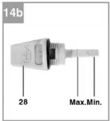
ASSEMBLY
Scope of delivery
Check that the product is complete. If any parts are missing, contact customer service or the store where you bought the product within five days after purchase. Remember that you must be able to present a valid receipt.
- Open the packaging and carefully remove the product.
- Remove all packaging materials and any transport protection parts.
- Check that the delivery is complete.
- Check if the product and accessories have been damaged during transport.
- If possible save the packaging until the warranty has expired.
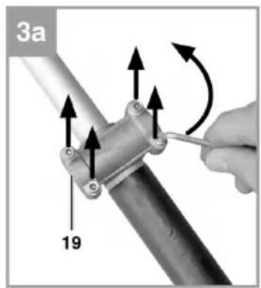
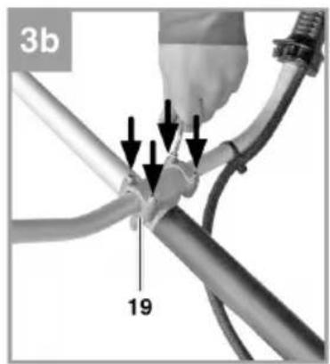
Fit the handlebar
- Fit the handlebar as described (diagrams 3a-3b).
- Adjust the handlebar.
-
Dismantle in the reverse order.
-
Tighten the screws when the optimal working position with the harness has been obtained.
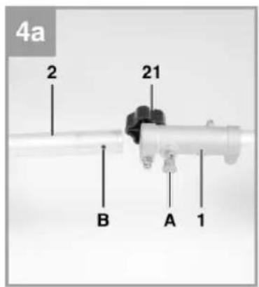
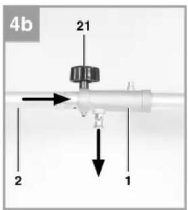
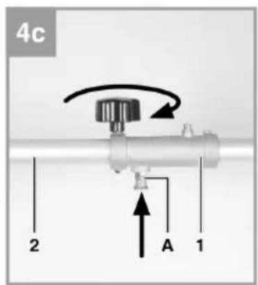
Fit the shaft (diagrams 4a - 4c)
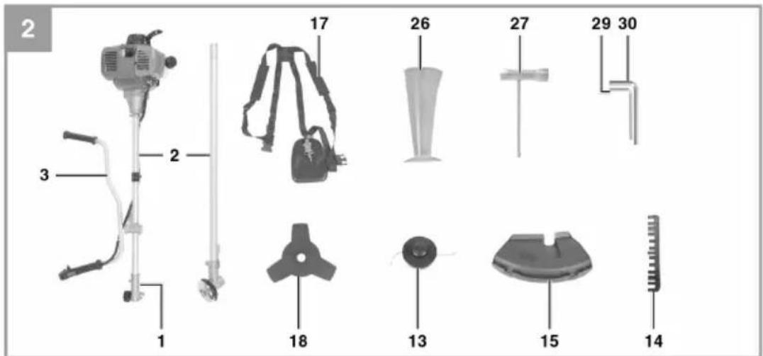
Tighten the locking arm (A) and carefully push in the shaft tube (diagram 4b/pos. 2) into the shaft connector. Make sure that the drive shafts inside the shaft tube slide into each other (turn round the spool head a little if necessary). The head on the locking arm (A) must snap into the hole (B). Tighten the star knob (21) as shown (diagram 4c).
Fit the blade guard
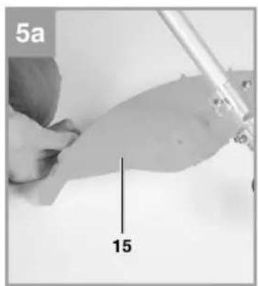
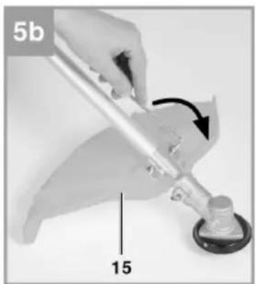
WARNING: If the machine is used with the clearing blade the guard must be fitted first. Fit the guard for the clearing blade as shown (diagrams 5a-5b).
Fitting/replacing the clearing blade
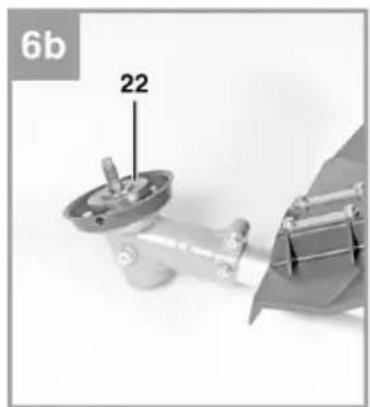
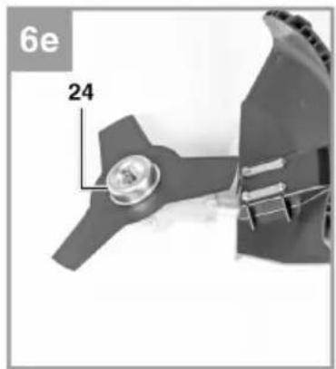
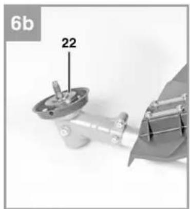
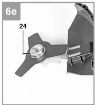
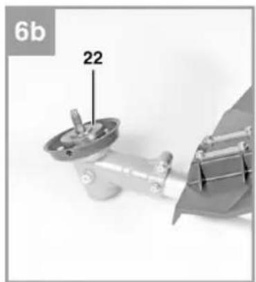
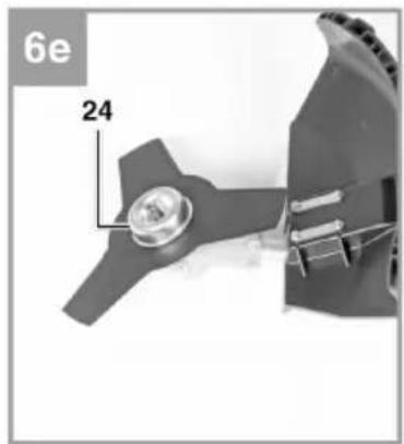
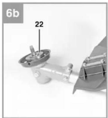
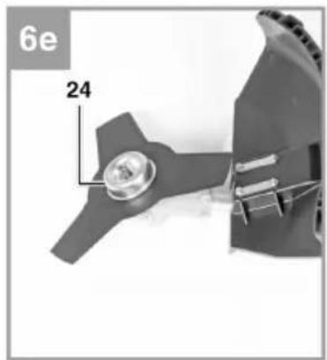
Diagrams 6a-6g show how the clearing blade should be fitted. Dismantle in the reverse order.
- Put the washer (22) on the cog axle (diagram 6b).
- Lock the clearing blade (18) on the carrier plate (diagram 6c).
- Put the pressure plate (23) over the threaded cog axle (diagram 6d).
-
Put on the guard for the pressure plate (24) (diagram 6e).
-
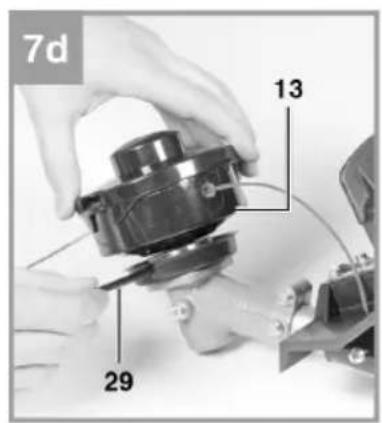
Locate the drill hole in the carrier plate, put the plate over the slot underneath and then lock with the supplied hex key (29).
- Tighten the bolt afterwards (25) (diagram 6f/6g). NOTE: Left-hand thread.
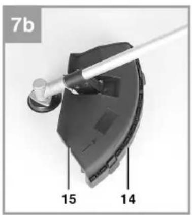
Fit the guard for the trimmer line on the guard for clearing blade.
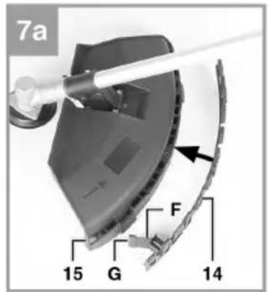
NOTE: The guard for the trimmer line must be fitted if you are using trimmer line (diagram 7a/ pos. 14). Fit the guard for the trimmer line as shown in diagrams 7a-7b. On the underside of the guard there is a blade (diagram 7a/pos. F) that cuts the line automatically. This is also covered by a guard (diagram 7a/pos. G). Remove this guard before using the machine and replace after finishing the work.
Fitting/replacing the trimmer head
Diagrams 7c-7d show how to fit the trimmer head. Dismantle in the reverse order. Locate the drill hole in the carrier plate, put the plate over the slot underneath and then lock with the supplied hex key (29). Screw the trimmer head on the thread.
NOTE: Left-hand thread.
Adjusting the height
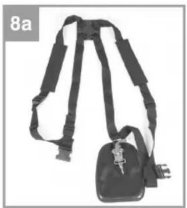
- Put on the harness as shown (diagrams 8a-8c).
- Hand the machine in the harness (diagram 8d).
- Adjust the optimal working and trimming position (diagram 8e).
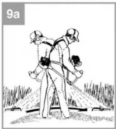
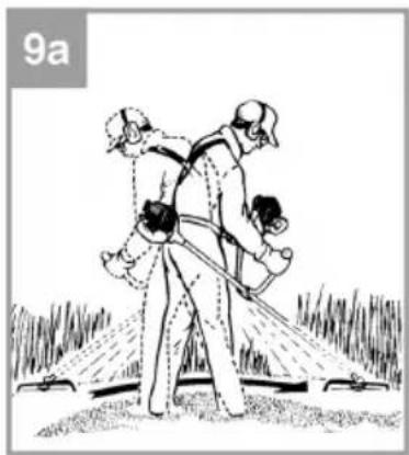
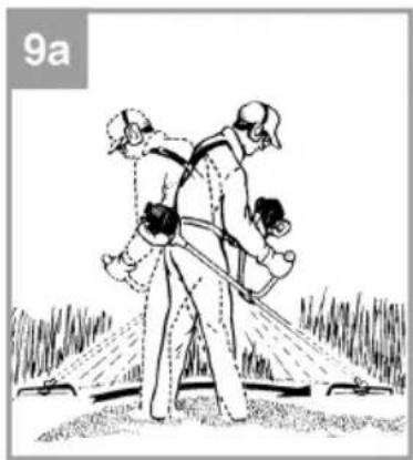
- Check the optimal adjustment of the length of harness by swinging the machine a few times over the ground while the engine is still switched off (diagram 9a).
NOTE: The harness has a quick-release. Pull the red strap (diagram 8f) if you need to quickly put the machine on the ground.
IMPORTANT: Always use the harness when working with the machine. Always put the harness on as soon as you have started the engine and it is idling. Switch off the engine before taking off the harness.
USE
Before use
Always check the following before using the machine:
– That the fuel system is not leaking.
- That the safety devices and cutting devices are complete and in good condition.
– That all the screw unions are tightened.
– That all moving parts run smoothly.
Fill up with fuel.
Unscrew the filler cap (diagram 1/pos. 6) and fill the tank with fuel with a filler tube. Make sure not to overfill the tank so that petrol runs out. Wipe up any spilt fuel and wait until the petrol fumes have evaporated (ignition risk). Screw on the filler cap.
Fill with oil
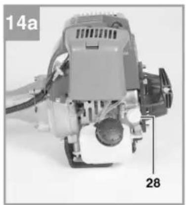
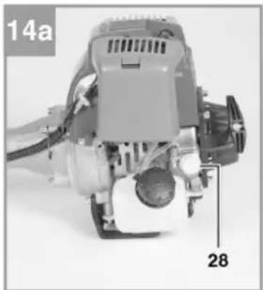
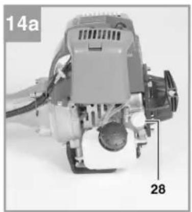
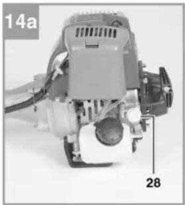
Open the oil filler plug (diagram 14a/pos. 28) and fill up with engine oil (15W40) to the top marking (max) on the dipstick (diagram 14b). The oil tank holds about 0.08 litres.
IMPORTANT: Fill up with engine oil and petrol before starting for the first time.
USE
Take local noise regulations into consideration. They can differ in different localities.
Starting a cold engine
- Fill the petrol tank.
- Place the machine on a firm, level surface.
- Press the fuel pump (primer) (diagram 1/pos. 7) 10 times.
- Put the power switch (diagram 1/pos. 9) to "I".
-
Lock the throttle control. Press in the throttle lock (diagram 1/pos. 12) and then press the throttle control (diagram 1/pos. 11). Press the lock at the same time (diagram 1/pos. 10) to lock the throttle control.
-
Set the choke (diagram 1/pos. 5) to "".
-
Hold the machine firmly and pull the starter cord (diagram 1/pos. 4) until you feel a resistance. Now pull the starter cord quickly six times. The machine should now start. NOTE: Do not let the starter cord snap back. This can cause damage. If the engine starts set the choke immediately to "♦" and allow the engine to run warm for about 60 seconds. WARNING: Because the throttle control is locked the tool starts to immediately rotate when the engine starts. Arrest the throttle control by pushing it in.
-
Repeat steps 4–6 if the engine does not start. Note: If the engine does not start after several attempts, read the "Troubleshooting" chapter. Note: Always pull the starter cord straight out. If the cord is pulled at an angle this will cause friction on the eyelet. This friction exposes the cord to unnecessary wear, which means it will wear out more quickly. Always keep hold of the starter handle when the cord pulls back into the machine.
-
Never allow the cord to snap back after it is pulled out.
Starting a hot engine
This applies when the machine was switched off no more than 15-20 minutes ago.
- Place the machine on a firm, level surface.
- Set the switch to "I".
- Hold the machine firmly and pull the starter cord until you feel a resistance. Now pull the starter cord quickly. After 1-2 pulls the machine should start. If the machine does not start after six pulls, follow steps 1-7 under "Starting a cold engine".
Switching off the engine for emergency stop
Set the switch to "Stop" and "O" to stop the machine immediately.
Switching off the engine during normal use
Release the throttle control and wait until the engine is idling. Now set the switch to "Stop" and "O".
Working instructions
Before using the machine go through and practice the different ways of working with the machine, with the engine switched off.
WORKING WITH THE CLEARING SAW
Feeding out trimmer line
WARNING: Do not use metal wire or any kind of plastic coated metal wire in the trimmer head. These types of wires can result in serious injury to the user. To feed out the trimmer line run the engine at full speed while tapping the trimmer head against the ground. The line will then feed out automatically. The blade on the guard cuts off the line to the correct length (diagram 26).
NOTE: Remove residual grass and weeds to prevent the shaft overheating. Residual grass and weeds can stick under the guard (diagram 27) and prevent the shaft from cooling properly. Carefully remove with a screwdriver or other tool.
Different methods of trimming
The machine can be used to trim weeds and high grass at inaccessible places, along fences, walls and foundations, and round trees. The machine can also be used to “clear” vegetation in preparation for making a garden. This method can also be used to clear an area.
Note: Even if the machine is used carefully, trimming along foundations, stone or concrete walls, means that the line wears down more quickly than usual.
Trimming/clearing
Swing the machine from side to side like a scythe. Keep the trimmer head parallel to the ground. Check the terrain and decide the intended trimming height. Guide and hold the trimmer head at the intended height to achieve a uniform result (diagram 28).
Low trimming
Tilt the trimmer slightly forward so that the underside of the trimmer head is over the ground and the line hits the right place. Always trim away from yourself. Never trim towards yourself.
Trimming by fences/foundations
Walk slowly forward with the trimmer towards chicken wire, wooden fences, stone walls and foundations, without allowing the line to hit the obstruction. If the line hits stones, stone walls or foundations it will be torn off or frayed. The line will be cut off if it goes against wires.
Trimming round trees
When trimming round trees do not allow the line to touch the truck. Walk round the tree trimming from left to right. Move the tip of the line forward to the grass or weeds and tilt the spool forwards slightly.
Clearing
NOTE: Be very careful when clearing. Make sure to keep a distance of at least 30 metres between yourself and other persons or animals.
Clearing involves trimming all the vegetation down to the ground. Tilt the line spool at an angle of 30^ to the right. Adjust the handle to the required position. Note that this trimming method involves more danger for the user, persons and animals in the vicinity, and that there is a risk of material damage if objects (e.g. stones) are thrown up (diagram 29).
WARNING: Do not use the machine to clear objects from paths etc. The machine is powerful tool and small stones and other objects can easily be thrown 15 metres or even further. This means there is a risk of personal injury and damage to cars, buildings and windows.
Sawing
IMPORTANT: The machine is not intended for sawing.
Unblocking the blade
Switch off the engine immediately if the blade gets blocked by vegetation. Remove grass and weeds from the machine before starting it again.
Preventing kick-back
When using the clearing blade there is a risk of kick-back if the blade hits solid objects (trunks, branches, stumps, stones, etc.). The machine then kicks back in the opposite direction to the direction of rotation of the machine. This can cause the user to lose control of the machine. Never use the clearing blade near fencing, metal posts, boundary stones or foundations. When cutting thick stalks, position these as shown in diagram 30 to avoid kick-back. NOTE: The maximum thickness for cutting brushwood is ∅ 13 mm
MAINTENANCE
IMPORTANT: Switch off the machine and release the spark plug lead before maintenance.
Replacing the trimmer head/trimmer line
- Remove the trimmer head (13) as shown. Press the spool together (diagram 12a) and take off one half (diagram 12b).
- Take out the trimmer spool from the cover (diagram 12c).
- Remove any residual trimmer line.
- Place the new trimmer line in the middle and then put the eyelet in the slot on the spool divider (diagram 12d).
- Keep the line stretched and wind it up anticlockwise. The spool divider separates both ends of the nylon wire (diagram 12e).
-
Hook the last 15 cm of both ends in the line retainers on the spool (diagram 12f).
-
Put both line ends through the metal eyelets in the trimmer head cover (diagram 12b).
- Press the spool in the cover (diagram 12a).
- Cut off any surplus line until about 13 cm is left. This reduces the pressure on the engine during starting and warming up.
- Replace the trimmer head. See item 5.1.6. Skip items 3-6 if replacing the complete trimmer head.
Sharpening the guard blade
The guard blade can become blunt in time. If this is the case, undo the screws holding the blade to the guard. Secure the blade in a vice. Sharpen the blade with a flat file, making sure not to change the angle of the blade. File in just one direction.
Maintaining the air filter
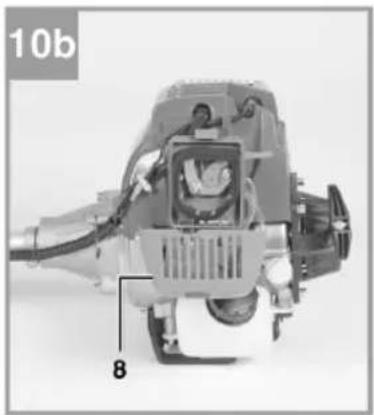
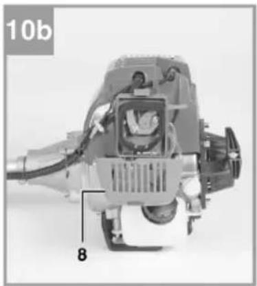
A dirty air filter reduces the performance of the engine by reducing the air supply to the carburettor. Check the filter at regular intervals. The air filter should be checked every 25 hours of operation and cleaned when necessary. Check the air filter more often if the air is very dusty.
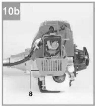
- Remove the air filter cover (diagram 10a).
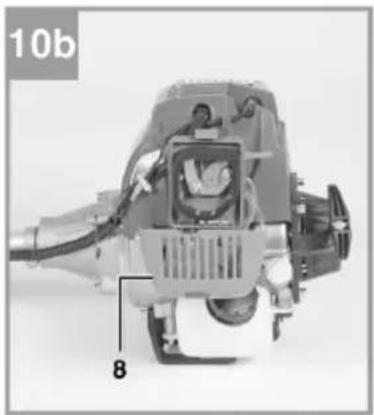
- Take out the filter unit (diagram 10b/10c).
- Clean the filter unit by tapping it, or by blowing it clean with compressed air.
- Replace in the reverse order.
WARNING: Never clean the air filter with petrol or flammable solvents.
Maintaining the spark plug
Check whether the spark plug is fouled for the first time after 10 hours of operation. Check the spark plug after that every 50 hours of operation.
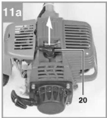
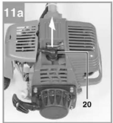
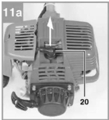
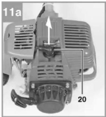
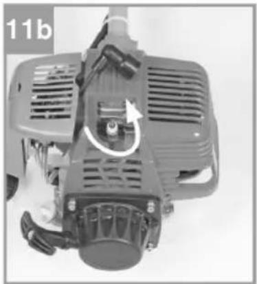
- Undo the spark plug lead (20) (diagram 11a).
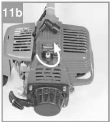
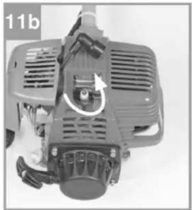
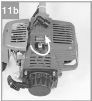
- Unscrew the spark plug (diagram 11b) with the supplied spanner (27).
- Check the electrode gap. The electrode gap should be 0.6 mm.
- Clean if necessary with a copper wire brush.
- Screw in the spark plug. Tighten with 12 to 15 Nm.
Carburettor settings
NOTE: Only an authorised service centre can adjust the carburettor. The air filter must be removed first before working on the carburettor, see description (diagrams 10a-10c).
Adjusting the throttle wire
If the maximum speed of the machine can no longer be attained and all other causes given in Troubleshooting can be excluded, it may be necessary to adjust the throttle wire. First check if the carburettor opens fully when the throttle control is pressed all the way in. This is the case if the carburettor damper (diagram 13a) is fully open at full throttle. Diagram 13a shows the correct adjustment. The wire needs adjusting if the carburettor damper is not fully open. The following steps are necessary to adjust the throttle wire:
- Undo the check nut (diagram 13b/pos. C) a few turns.
- Turn the adjuster screw (diagram 13b/pos. D) so that the carburettor damper is fully open, see diagram 13a, when the throttle control is pushed all the way in.
- Tighten the check nut again.
Adjusting the idling speed
Adjust the idling speed when the machine is still warm. The speed when the tool starts should by at least 1.25 times the idling speed. NOTE: The idling speed should only be adjusted by an authorised service centre.
Greasing the gear
Add a little gear grease (about 10 g) through the grease nipple (C) (diagram 7c) every 20 hours of operation.
Changing the oil and checking the oil level (before use)
The engine oil should be changed when the engine is still hot. Take the service information into consideration.
- Have a suitable container on hand when changing the oil.
- Open the oil filler plug (diagrams 14a-14b/pos. 28).
- Drain off the waste oil in a suitable container by tilting the engine.
- Fill up with engine oil (15W40) to the top marking (max) on the dipstick (diagram 14b).
NOTE: Recycle waste oil according to local regulations. Hand in waste oil to your nearest recycling centre. Do not mix different substances together with waste oil, e.g. anti-freeze or gearbox oil. Store the oil out of the reach of children and at a safe distance from sources of heat.
Cleaning
• Make sure to keep the handles free from oil so that you always have a firm grip on the machine.
- Clean the machine when necessary with a damp cloth and even a mild detergent.
NOTE: Always release the spark plug lead before cleaning. Never immerse the machine in water or any other liquids to clean it.
Storage
The machine must be prepared if it is to be stored for more than 30 days. Otherwise residual fuel in the carburettor will evaporate and leave a rubbery bottom sediment.
This can make it difficult to start the machine and may result in it having to be repaired.
-
Carefully remove the cap on the fuel tank to release any pressure in the tank.
Carefully empty the tank. -
Start the engine and run it until it stops. This drains the fuel out of the carburettor.
-
Wait for the engine to cool (about 5 minutes).
NOTE:
- Store the machine in a dry place, far away from sources of heat, e.g. stoves, gas powered hot water heaters etc.
- Store the machine in a safe and dry place out of the reach of children.
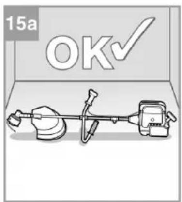
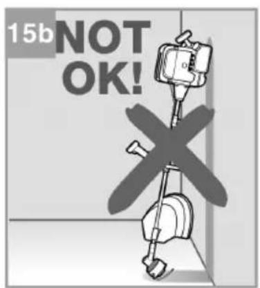
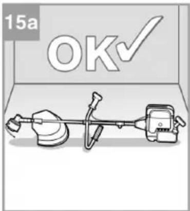
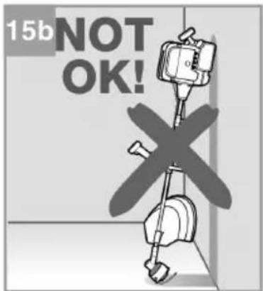
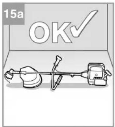
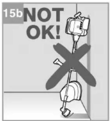
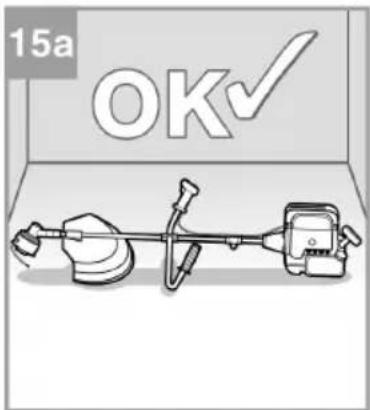
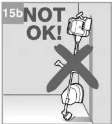
IMPORTANT: Store the machine as shown in diagram 15a. If the machine is hung up, stood up (diagram 15b) or stored on its side, engine oil will run into the combustion chamber, which will result in it not being possible to start the machine.
Using the machine again
- Unscrew the spark plug.
- Clean the spark plug and check the electrode gap.
- Replace the spark plug, or insert a new spark plug of the old one is worn.
Transport
Empty the fuel tank before transporting the machine. Remove any debris from machine with a brush. Dismantle the shaft as shown.
TROUBLESHOOTING
| Problem Possible cause Action | ||
| The machine will not start. The machine has tried to be started in the wrong way. | Follow the starting instructions. | |
| Carbon deposits or wetness on spark plug. | ||
| The carburettor is not properly adjusted. | ||
| The engine starts, but does not produce full power. | The choke is incorrectly set. | Set the choke in position "♠". |
| The air filter is dirty. Clean the air filter. | ||
| The carburettor is not properly adjusted. | Contact a service workshop. | |
| The engine runs unevenly. Incorrect electrode gap on spark plug. | Clean the spark plug and adjust the electrode gap, or insert a new spark plug. | |
| The carburettor is not properly adjusted. | ||
| The engine emits an abnormal amount of smoke. | The carburettor is not properly adjusted. | Contact a service workshop. |
CE
EC DECLARATION OF CONFORMITY
EG FÖRSÄKRAN OM ÖVERENSSTÄMMELSE
EF SAMSVARSERKLÆRING
DEKLARACJA ZGODNOŚCI WE

Jula AB, Box 363, SE-532 24 SKARA, SWEDEN
certify that the design and manufacturing of this product
RYDDESAG / WYKASZARKA
FBC310
31CC, 0,7kW
Item number / Artikelnummer / Artikkelnummer / Numer artykułu
721-489
Machinery Directive 2006/42/EC
EN ISO 11806-1:2011
Electromagnetic Compatibility Directive 2014/30/EU
EN ISO 14982:2009
Outdoor Noise Directive 2000/14/EC, amended by 2005/88/EC
This product was CE marked in year -16
Name and address of the person authorised to compile the technical file:
- Care for the environment!
- SVENSKA....5
- NORSK 28
- POLSKI 51
- ENGLISH 75
- SÄKERHETSANVISNINGAR
- MONTERING
- Leveransomfattning
- Leveransens omfang
- Stille inn tomgangsgass
- Smør girene
- MONTAŽ
- Kontrola dostawy
- Read the operating instructions carefully before use.
- Remaining risks
- Special safety instructions when using the trimmer head
- Special safety instructions when using the clearing blade
- Fuel
- Other safety instructions
- IMPORTANT:
- WARNING:
- Symbols
- Always wear ear protection.
- DESCRIPTION
- ILLUSTRATIONS
- ASSEMBLY
- Scope of delivery
- Fit the handlebar
- Fit the shaft (diagrams 4a - 4c)
- Fit the blade guard
- Fitting/replacing the clearing blade
- Fit the guard for the trimmer line on the guard for clearing blade.
- Fitting/replacing the trimmer head
- Adjusting the height
- USE
- Before use
- Fill up with fuel.
- Fill with oil
- Starting a cold engine
- Starting a hot engine
- Switching off the engine for emergency stop
- Switching off the engine during normal use
- Working instructions
- WORKING WITH THE CLEARING SAW
- Feeding out trimmer line
- Different methods of trimming
- Trimming/clearing
- Low trimming
- Trimming by fences/foundations
- Trimming round trees
- Clearing
- Sawing
- Unblocking the blade
- Preventing kick-back
- MAINTENANCE
- Replacing the trimmer head/trimmer line
- Sharpening the guard blade
- Maintaining the air filter
- Maintaining the spark plug
- Carburettor settings
- Adjusting the throttle wire
- Adjusting the idling speed
- Greasing the gear
- Changing the oil and checking the oil level (before use)
- Cleaning
- Storage
- NOTE:
- Using the machine again
- Transport
- TROUBLESHOOTING
- CE
- EC DECLARATION OF CONFORMITY
- EG FÖRSÄKRAN OM ÖVERENSSTÄMMELSE
- EF SAMSVARSERKLÆRING
- DEKLARACJA ZGODNOŚCI WE
- RYDDESAG / WYKASZARKA
- This product was CE marked in year -16
Brand : Meec Tools
Model : 721-489
Category : Brush cutter