
10032549 - Grill Klarstein - Free user manual and instructions
Find the device manual for free 10032549 Klarstein in PDF.


User questions about 10032549 Klarstein
0 question about this device. Answer the ones you know or ask your own.
Ask a new question about this device
Download the instructions for your Grill in PDF format for free! Find your manual 10032549 - Klarstein and take your electronic device back in hand. On this page are published all the documents necessary for the use of your device. 10032549 by Klarstein.
USER MANUAL 10032549 Klarstein
text_image
Exploded view diagram of a household appliance with numbered parts for identification| A | B | C | D |
 5/32"x32 5/32"x32 | 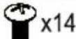 1/4"x20 1/4"x20 |  | 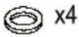 |
Einzelteilliste
natural_image
Technical line drawing of a rectangular enclosure with two circular components and mounting feet (no text or symbols)2
text_image
Three-step diagram showing a toilet, a tank, and a cup with directional arrows indicating motion.
text_image
Technical diagram of a mechanical device with labeled components and measurement indicators3
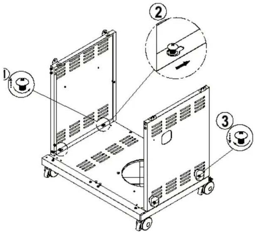
text_image
Technical diagram of a mechanical device with labeled parts and directional arrows indicating assembly or operation.4
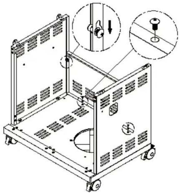
natural_image
Technical line drawing of a mechanical device with mounting holes and internal components, showing assembly details (no text or symbols)Bx4
5
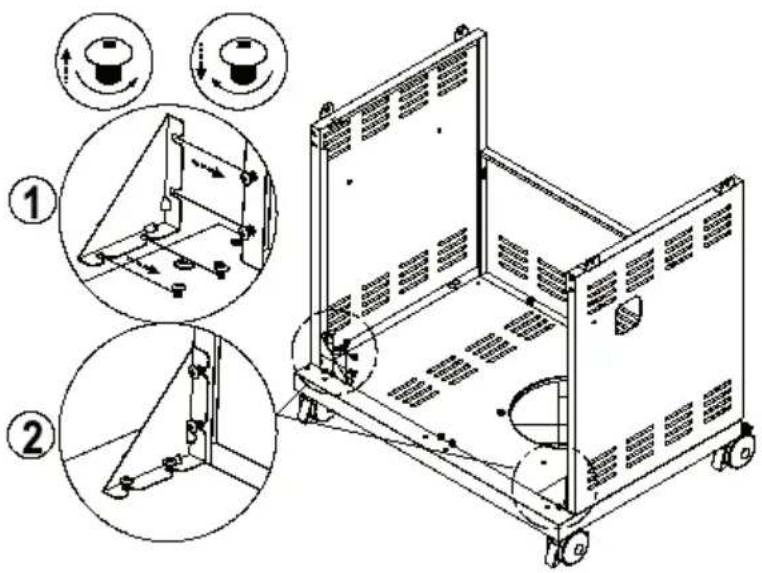
text_image
Technical diagram of a mechanical device with numbered annotations indicating assembly steps and component views6
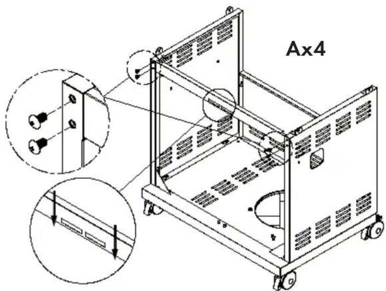
text_image
Ax47
natural_image
Technical line drawing of a portable gas stove with internal components and mounting holes (no text or labels)8
text_image
Bx49
text_image
Bx2 Dx210
text_image
Technical diagram of a mechanical device with labeled parts and three-step instructions for rotary switch operation.11
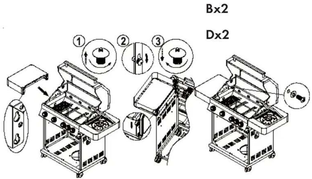
text_image
Bx2 Dx212
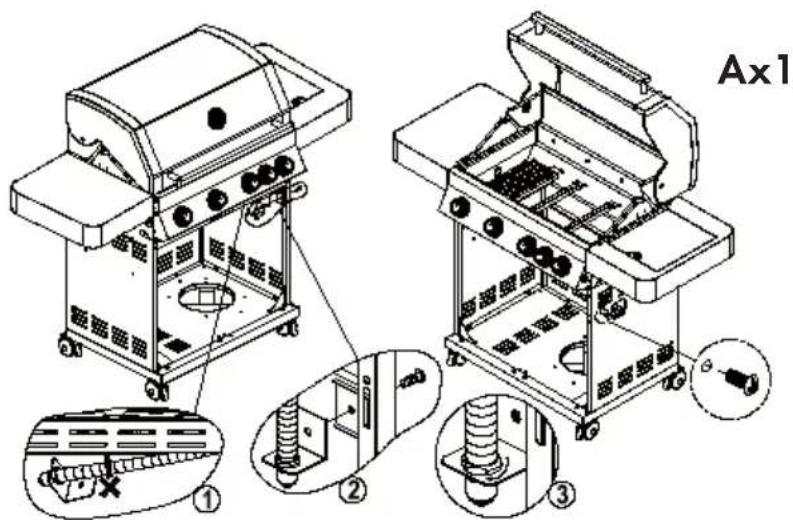
text_image
Ax1 ① ② ③13
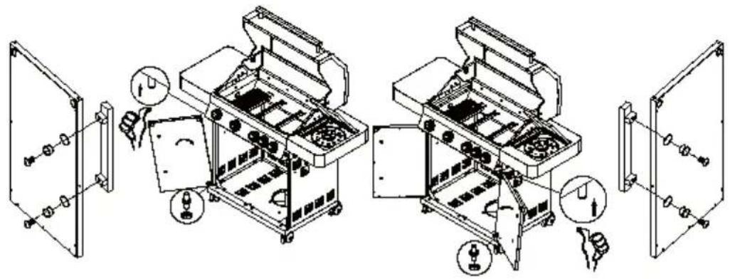
natural_image
Technical line drawing of a mechanical device with exploded view and close-up views (no text or symbols)14
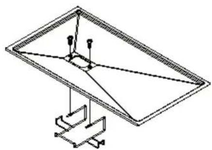
natural_image
Pure technical line drawing of a tilted rectangular frame with internal components and support structures (no text or symbols)Ax2
natural_image
Technical line drawing of a mechanical device with wheels and internal components, showing no text or symbols.15
text_image
Technical diagram of an electrical enclosure with labeled components and exploded view, showing battery assembly steps.17
natural_image
Technical line drawing of a mechanical device with internal components and mounting holes (no text or symbols)flowchart
graph TD
    A["1: Washing"] --> B["2: Washer"]
    B --> C["3: Soap & Wash"]
    C --> D["4: A Sewer with Stamped Tool"]
    D --> E["50% Inspection"]
    E --> F["6: Stamped Tool with Cover"]
    F --> G["7: Stamped Tool with Screw"]
    G --> H["8: Stamped Tool with Pulling"]
    H --> I["9: Stamped Tool with Stamping"]
    I --> J["10: Stamped Tool with Stopping"]
    J --> K["11: Stamped Tool with Stopping"]
    K --> L["12: Stamped Tool with Stopping"]
ANZÜNDEN
natural_image
Symbol of a trash bin crossed with a diagonal line, no text or labels presentCongratulations on purchasing this equipment. Please read this manual carefully and take care of the following hints to avoid damages. Any failure caused by ignoring the mentioned items and cautions mentioned in the instruction manual are not covered by our warranty and any liability.
CONTENT
Safety Instructions 27
Individual Parts and Screws 28
Assembly 30
Connecting the Gas Cylinder to the Unit 38
Checking for Leaks 40
Ignition 42
Cleaning and Care 43
Troubleshooting 44
Hints on Disposal 45
DECLARATION OF CONFORMITY
Producer:
Chal-Tec GmbH, Wallstraße 16, 10179 Berlin, Germany.

This product is conform to the following European Directives:
Regulation (EU) 2016/426
KLARSTEIN
| Item number | K104M1BKD1S /10032549 | ||||
| Description | Outdoor Gas Grill | ||||
| Gastype | I3+(28-30/37) | I3B/P(30) | I3B/P(37) | I3B/P(50) | |
| Gas Pressure | Butan(G30) | Propan(G31) | Butan/Propan | Butan/Propan | Butan/Propan |
| Supply Pressure | 28-30mbar | 37mbar | 30mbar | 37mbar | 50mbar |
| Total Nominal Heat Inputs | Main Burner: 10.5 kW/h (763 g/h)Side Burner: 3 kW (218 g/h)Side Burner (infrared): 3.5 kW (254 g/h) | ||||
| Injector SizeMain BurnerSide BurnerSide Burner (infrared) | 0,92 mm0,88 mm0,92 mm | 0,92 mm0,88 mm0,92 mm | 0,92 mm0,88 mm0,92 mm | 0,86 mm0,79 mm0,86 mm | 0,81 mm0,75 mm0,81 mm |
| Country of Destination | AT, CH, DE, CZ, SK | ||||
| Power supply LED | 4x 1.5 V LED Lampe | ||||
| Identification Number | 0359CP1429 | ||||
| Serial Number | 100325490011804 | ||||
| Important Notes | Only use the device outdoors.Read the operating instructions carefully.CAUTION: The accessible parts can become very hot during use. Keep children away from the device. | ||||
Chal-Tec GmbH
Wallstraße 16
10179 Berlin
Germany
CE 0359-19 0359
SAFETYINSTRUCTIONS
• For outdoor use only
- Read the operating instructions
- Keep the operating instructions for future reference.

WARNING
Danger of fire or explosion.
Follow the instructions.
- Read the user manual before using the device.
- Keep the operating instructions for future reference.
- Only use outdoors.
- Accessible parts can get very hot. Keep children away.
• Do not move the device during use.
• After use, close the gas tap on the gas cylinder.
• Do not convert the device.
• The appliance must be kept away while using fl ammable substances. - The pressure regulator and hose must be properly connected to the unit. To tighten the nut on the connecting thread, a wrench must be used.
- Do not store gas cylinders in the gas barbecue cart during use. It is prohibited to put gas cylinders in the device.
If you smell gas:
- Turn the gas tap on the gas cylinder until it is closed.
- Extinguish all open flames. Do not operate electrical appliances.
- Ventilate the area.
- Check for leaks as described in the instruction manual.
- If odor persists, contact the dealer or gas supplier.
Precautions
- Check all connections after filling the gas cylinder.
- Never check for leaks with a match or open flames.
- Never store gasoline or other fl ammable vapors near the gas grill.
- LP gas cylinders that are not connected should not be kept near this unit or any other device.
Note: Be sure to remove the protective plastic before assembly.
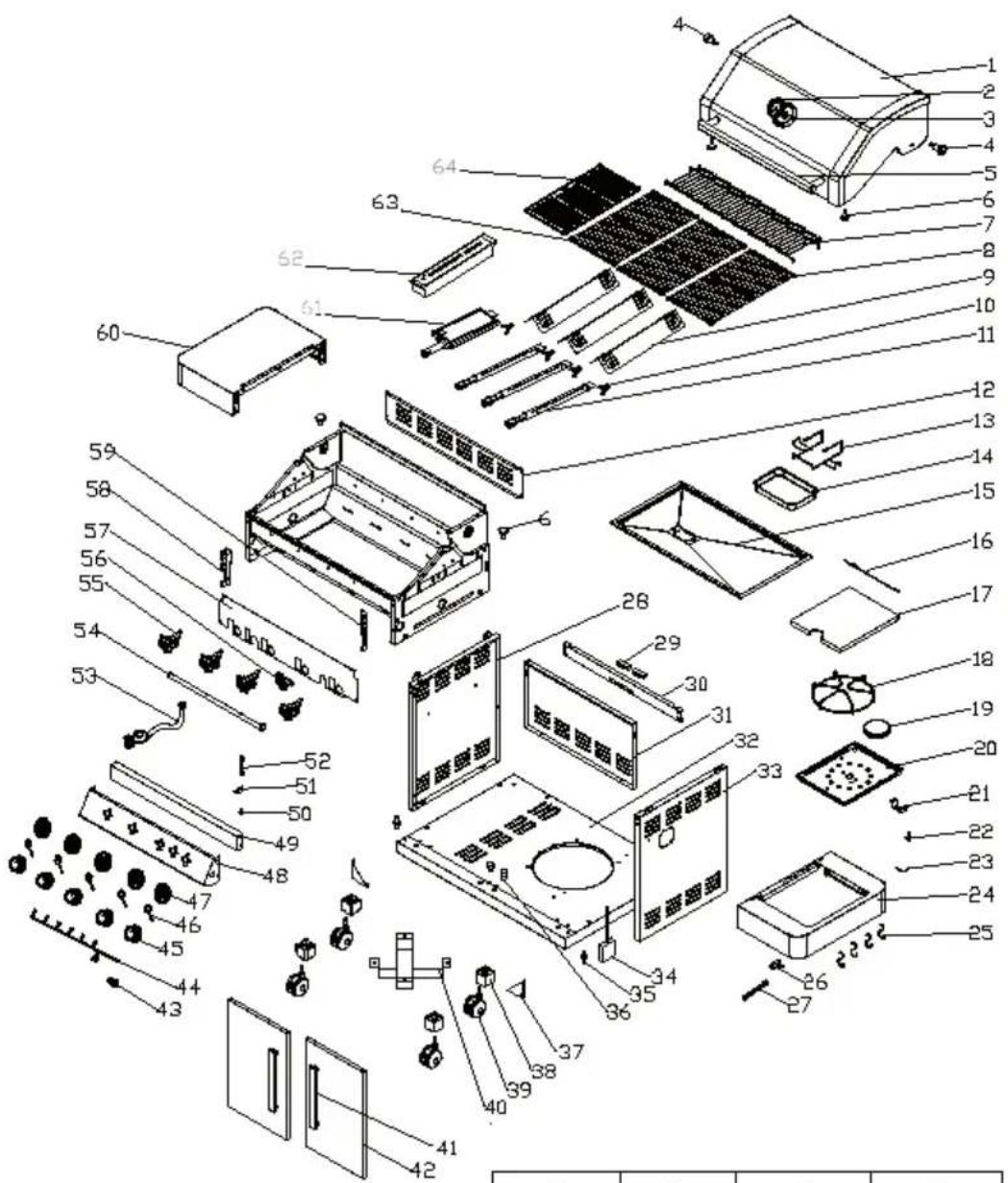
INDIVIDUAL PARTS AND SCREWS
text_image
Exploded view diagram of a solar panel assembly with numbered components for identification| A | B | C | D |
 x9 5/32"x32 x9 5/32"x32 |  x14 1/4"x20 x14 1/4"x20 |  x2 x2 |  x4 x4 |
Parts List
| No. | Name Qty. No. Name Qty. | ||||
| 1 | Lid 1 33 Right panel of cabinet | 1 | |||
| 2 | Thermometer 1 34 Battery box | 1 | |||
| 3 | Base of thermometer 1 35 Door spindle | 2 | |||
| 4 | Spindle of lid 2 36 Door bolt 2 | ||||
| 5 | Lid hander | 1 37 Shelf bracket 4 | |||
| 6 | Crash pad | 4 | 38 | Wheel foot plug | 4 |
| 7 | Warming rack | 1 | 39 | casters | 4 |
| 8 | Cooking grid(450x295) | 1 | 40 | Gas cylinder bracket | 2 |
| 9 | Flame term | 3 | 41 | Door handles | 2 |
| 10 | Snap spring | 4 | 42 | Doors | 2 |
| 11 | Main burner | 4 | 43 | Button | 1 |
| 12 | Rear panel of cooking room | 1 | 44 Lamp board connection | 1 | |
| 13 | Hanger of grease cup | 4 | 45 | Control knob | 4 |
| 14 | Grease cup | 1 | 46 | Lamp board | 4 |
| 15 | Grease tray | 1 | 47 | Base of knob | 4 |
| 16 | Spin axis of side burner | 1 | 48 | Control panel | 1 |
| 17 | Lid of side burner | 1 | 49 | Decoration panel | 1 |
| 18 | Pan support | 1 | 50 | Connector | 1 |
| 19 | Side burner | 1 | 51 | Fixed plate | 1 |
| 20 | Bottom of side burner | 1 | 52 | Corrugated pipe | 1 |
| 21 | Connector of side burner | 1 | 53 | Gas regulator | 1 |
| 22 | Spark electrode of side burner | 1 | 54 Tracheal combination | 1 | |
| 23 | Wire of side burner | 1 | 55 | Gas check of main burner | 4 |
| 24 | Right side table | 4 | 56 | Gas check of side burner | 1 |
| 25 | Hook | 1 | 57 | Inner control panel | 1 |
| 26 | Nozzle of side burner | 1 | 58 | Left connect plate | 1 |
| 27 | Corrugated pipe of side burner | 1 | 59 Right connect plate | 1 | |
| 28 | Left panel of cabinet | 1 | 60 | Left side table | 1 |
| 29 | Door magnet | 2 | 61 | Infrared main burner | 1 |
| 30 | Door beam | 1 | 62 | Smoker box | 1 |
| 31 | Rear panel of cabinet | 1 | 63 | Cooking grid(450x195) | 2 |
| 32 | Bottom panel of cabinet | 1 | 64 | Cooking plate | 1 |
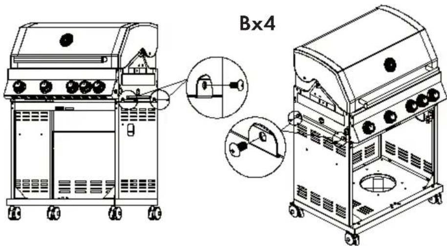
ASSEMBLY

CAUTION
Risk of injury. Although every effort has been made to remove sharp edges from the grill, handle all parts with care to avoid injury.
Required tools: Either a Phillips screwdriver or a fl at-head screwdriver. Either a wrench or pliers.
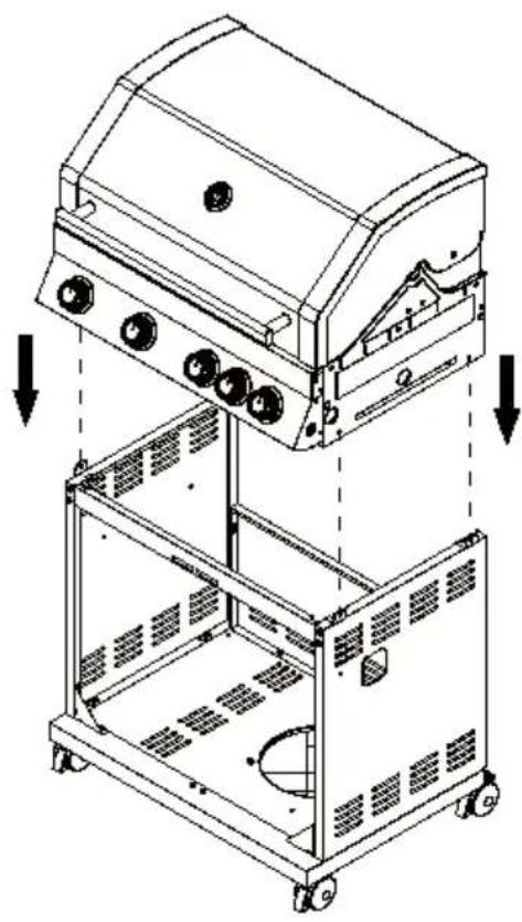
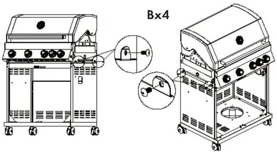
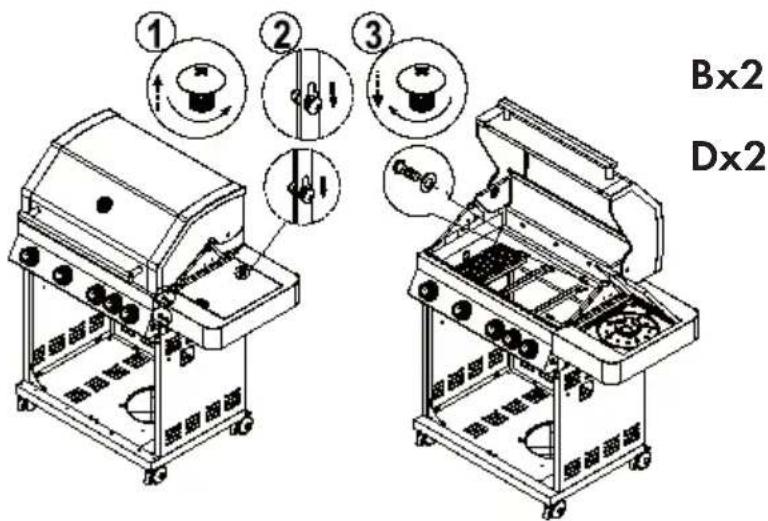
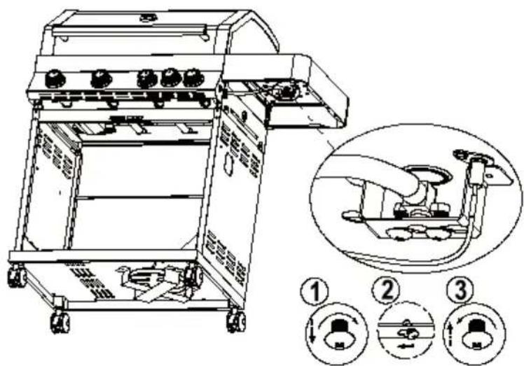
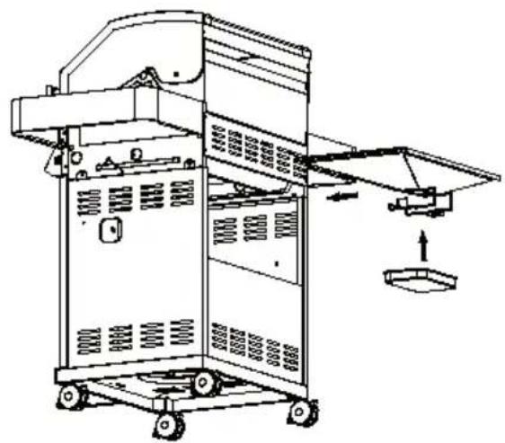
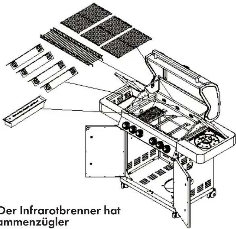
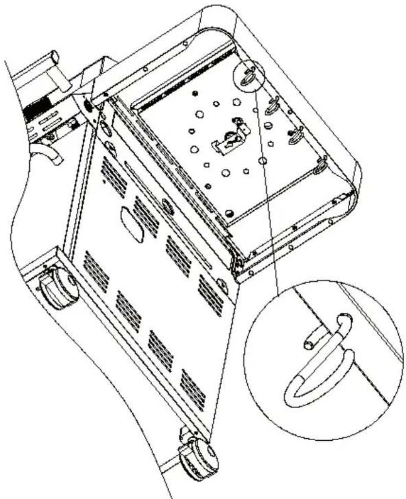
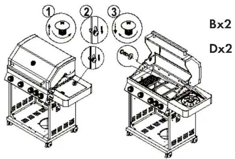
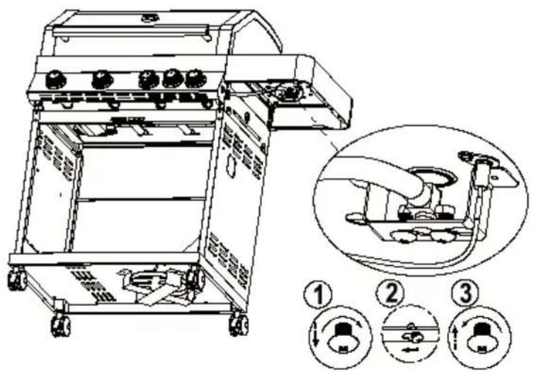
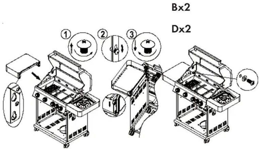
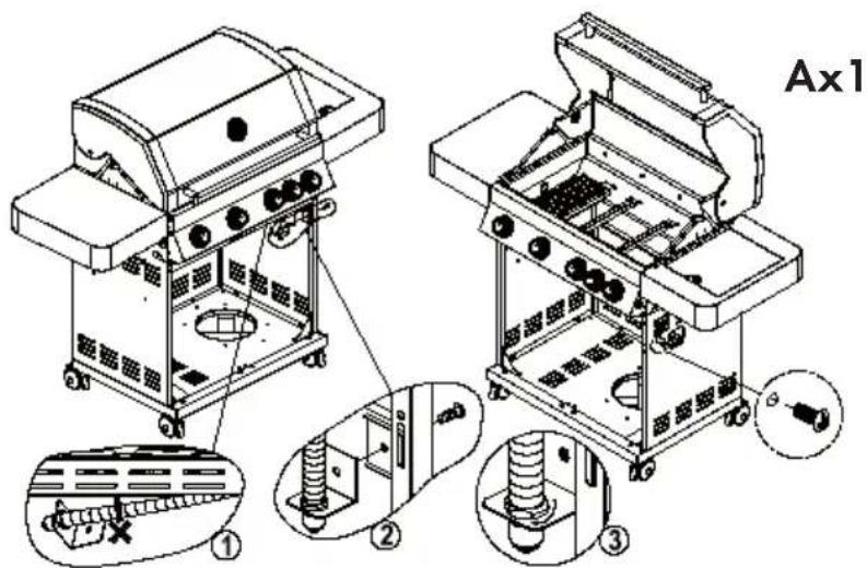
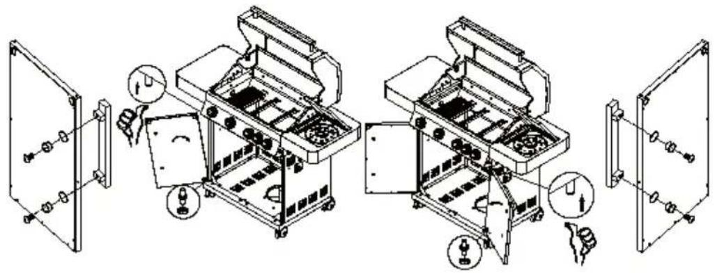
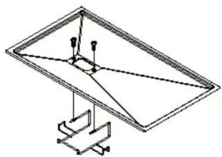
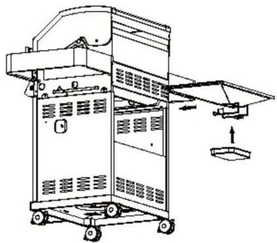
Assembly: Read the operating instructions completely before proceeding. Find a large, clean area where you can set up the grill cart. Read through the list of parts included in delivery and look at the assembly pictures. Construction of the grill includes many large parts. The assembly requires 2 people.
Note: Remove plastic caps before assembly.
1
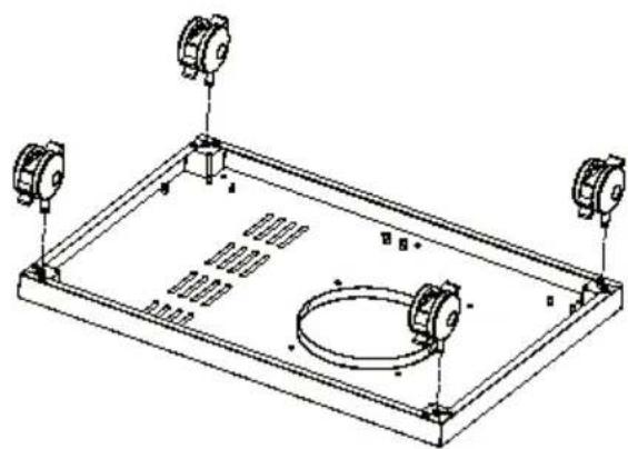
natural_image
Technical line drawing of a rectangular enclosure with two circular components and mounting feet (no text or symbols)2
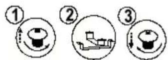
text_image
Three-step diagram showing a toilet, a boat, and a cup with directional arrows indicating motion.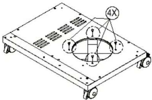
text_image
4X3
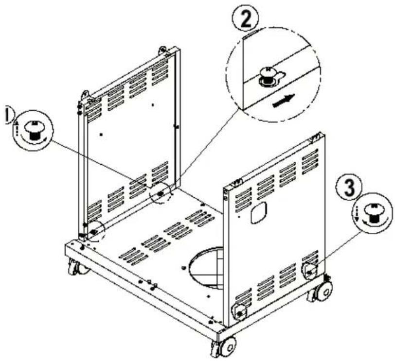
text_image
Technical diagram of a mechanical device with labeled parts and directional arrows indicating assembly or operation.4
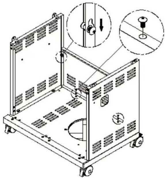
natural_image
Technical line drawing of a mechanical device with mounting holes and internal components, showing assembly details (no text or symbols)Bx4
5
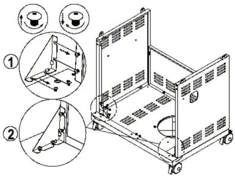
text_image
Technical diagram of a mechanical device with numbered annotations indicating assembly steps and component views6
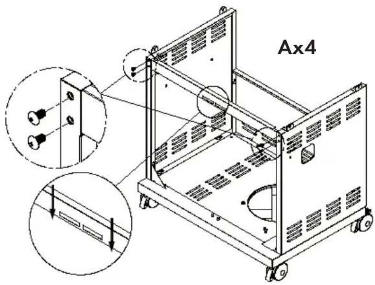
text_image
Ax47
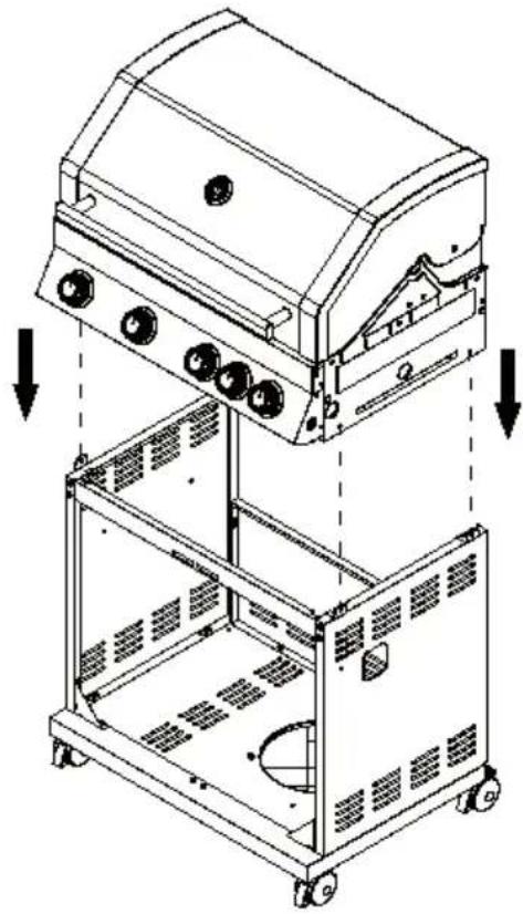
natural_image
Technical line drawing of a portable gas stove with mounting holes and internal compartments (no text or symbols)8
text_image
Bx49
text_image
Bx2 Dx210
text_image
Technical diagram of a portable air purifier with labeled parts and three-step instructions for handling the device.11
text_image
Bx2 Dx212
text_image
Ax1 ① ② ③13
natural_image
Technical line drawing of a mechanical device with exploded view and close-up views (no text or symbols)14
natural_image
Pure technical line drawing of a tilted rectangular frame with internal components and support structures (no text or symbols)Ax2
natural_image
Technical line drawing of a mechanical device with wheels and internal components, showing no text or symbols.15
text_image
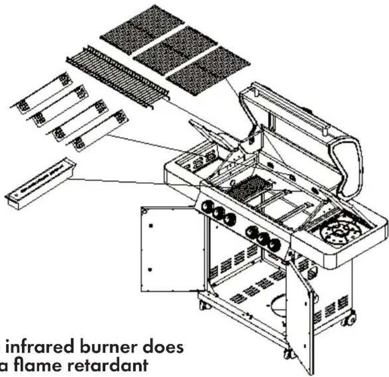
infrared burner does a flame retardantNote: The infrared burner does not have a flame retardant
16
text_image
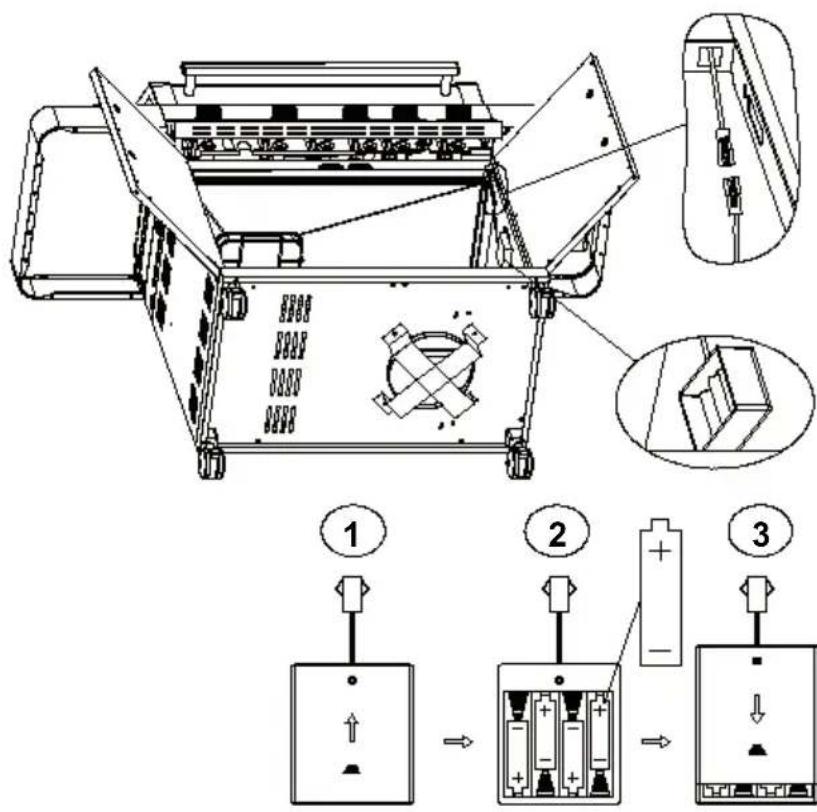
Technical diagram of an electrical enclosure with labeled components and exploded view, showing battery assembly steps.17
natural_image
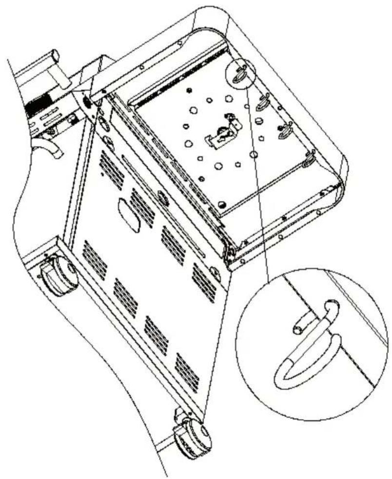
Technical line drawing of a device rear panel with mounting holes and internal components, plus an inset close-up of a ring component (no text or symbols)CONNECTING THE GAS CYLINDER TO THE UNIT
- The gas grill can be operated with a 5 kg gas cylinder. The maximum diameter should be 31 cm and the maximum height 60 cm. Follow the technical information as described in the user manual. Ask your local dealer for the appropriate gas cylinder for the gas grill.
- The unit is intended for use with a low-pressure butane or propane cylinder with a flexible hose connected to a low-pressure regulator only.
- The hose must be connected to the pressure regulator and hose clamps. Make sure that the hose does not come into contact with hot surfaces.
- Use a suitable pressure regulator that complies with EN 12864 and EN 16129. The regulator and hose must comply with local regulations.
Pressure regulator and hose
Use only pressure regulators and hoses suitable for propane gas for the pressure specified above. The life expectancy of a pressure regulator is 2 years.
Using a wrong pressure regulator is not safe. Before using the grill, make sure that you have the right accessories.
Note: The hose must comply with the applicable EU standard and local laws. Worn or damaged hoses must be replaced. Make sure that the hose is not obstructed or kinked and does not come into contact with part of the grill when connecting.
Flexible hoses
Do not bend the hose when using the grill. The hose must comply with the relevant standards. The length of the hose must not exceed 1.5 m. In Finland, the length may not exceed 1.20 m.
Storage of the grill
It is possible to store the grill indoors as long as the gas cylinder has been disconnected from the grill. If the grill is not going to be used for a long time, it should be stored in its original packaging in a dust-free environment.
Gas cylinders
- The gas cylinder must not be dropped or handled roughly. If the grill is not in use, the gas cylinder must be disconnected. Replace the protective cap after disconnecting from the grill. The gas cylinder must be placed outside the grill.
- Always change the gas cylinder in a well-ventilated area, away from ignition sources such as flames, sparks or heat sources.
- Gas cylinders must be stored outdoors, out of the reach of children. They must never be stored above a temperature of 50^ C. Do not store near flames, pilot lights or other sources of ignition. Do not smoke.
- The gas grill is designed for outdoor use, away from combustible materials.
- It is essential that there is no obstruction from an overhang and that a minimum distance of 1 m from the sides of the unit is maintained.
- The air openings on the grill must not be blocked. The grill must be set up on an even, stable surface. The device must be protected from direct sunlight and protected against dripping water (e.g. rain).
Connection to the grill
- Before use, make sure that there are no deposits or contaminants at the top of the gas cylinder, the pressure regulator, the burner or the burner openings. Spiders and insects can nest at the burner opening or at pipe openings. A clogged burner can cause a fire under the unit.
- Clean the burner openings with a sturdy pipe brush.
- Fix the hose on the connection thread on the grill with a wrench. If the hose is replaced, it must be connected with clamps on the grill and on the pressure regulator. Disconnect the pressure regulator from the gas cylinder if you are not using the grill (see instructions for the pressure regulator).
- The grill must be placed in a well ventilated place. Do not block the flow of combustion air during use.
CHECKING FOR LEAKS
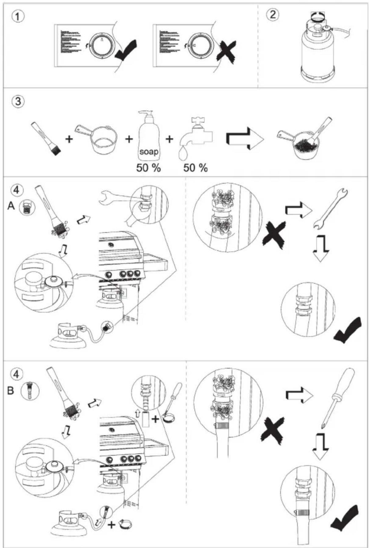
• Mix 50-80 ml of leak detection solution. Use 1 part detergent and 3 parts water.
• The valve must be OFF.
- Connect the pressure regulator with the gas cylinder and the inlet valve of the burner. Check that the connections are secure and let in the gas by turning the valve to ON.
- Spread the detergent solution on the hose and all connections. If bubbles appear, there is a leak that you need to fix. Test again after correcting the problem source.
- Close the gas cylinder after the test. If you find a leak and cannot fix the leak, do not try to fix it yourself. Contact a specialist.
flowchart
graph TD
    A["1: Washing"] --> B["2: Washer"]
    B --> C["3: Soap & Washing"]
    C --> D["4: A Sewer & Hammer"]
    D --> E["5: Finishing & Cleaning"]
    E --> F["6: Stopping & Repair"]
    F --> G["7: Stopping & Repair"]
    G --> H["8: Stopping & Repair"]
IGNITION
- Open the hood of the grill before attempting to ignite the burners.
- Set all buttons to the OFF position.
-
Connect the pressure regulator to the gas cylinder. Turn on gas supply to the pressure regulator. Perform the leak test between the gas cylinder and the pressure regulator.
-
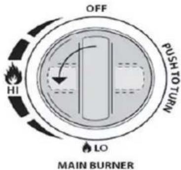
Push the front left knob down. Hold the button down while turning it counterclockwise towards HIGH (you will hear a click). This ignites the burner. Check if the burner has ignited. If not, repeat the process.
-
If the burner has not lit after trying again, wait 5 minutes and repeat step 4.
-
Adjust the heat by turning the knob to the High / Low position.
-
If the burner does not work, ignite it with a match at the ignition hole on the side of the unit.
text_image
OFF HI LO PUSH TO TURN MAIN BURNER-
To ignite the remaining burners from left to right in sequence, repeat the step. The adjacent burner is ignited via the ignition channel between the burners.
-
To turn the grill off, turn the valve on the gas cylinder. Then turn the knob clockwise to the OFF position.

Attention:
If the burner does not ignite, turn the knob (clockwise). Turn the valve of the gas cylinder until closed.
- Before using for the first time, turn the grill on for 15 minutes, with the hood closed, to the lowest flame. This cleans the inside of the device and makes the paint smells evaporate.
- Clean the grill after each use. Do not use scouring agents or fl ammable cleaners, as this may damage parts of the grill and cause a fi re. Clean with clean soapy water.
- The accessible parts of the grill can become very hot. Keep young children away at all times (even during the cooling off period).
• Use protective gloves when handling hot parts.
CLEANING AND CARE

WARNING
Danger of burns. All cleaning and maintenance must be carried out when the grill is cold and the gas supply to the gas cylinder has been shut off.
Cleaning:
Burn the grill for about 15 minutes after each use. This reduces the amount of food remaining.
Outer surfaces:
Use a mild detergent or a baking soda solution. Non-abrasive scourers may be used to remove stubborn stains. If the paint on the inside of the grill looks like it is peeling off, it is actually charred grease that is peeling off. Clean with a strong soap solution. Then rinse with water and let dry completely.
Grill surface:
Remove any residue with a brush, scraper or cleaning pad with a soap solution. Rinse with water and allow to dry.
Wood surfaces:
Wash with a soft cloth and soapy water. Rinse off with water. Do not use abrasive cleaners, grease-dissolving cleaners or detergent concentrates for wooden surfaces of the grill.
Grill grate:
Use a mild soapy solution. A non-abrasive scourer may be used for stubborn stains.
Cleaning the burner unit

WARNING
Danger of burns. All cleaning and maintenance must be carried out when the grill is cold and the gas supply to the gas cylinder has been shut off.
- Turn the gas supply on the control dial off and disconnect the connection to the gas cylinder.
- Remove the cooled grate.
- Clean the burners with a soft brush or blow them clean with compressed air.
- Clean the clogged parts with a pipe brush and stiff wire.
- Check the burner for damage (cracks or holes). If damage has been found, replace with a new burner. Make sure that the gas valve openings are correctly positioned.
TROUBLESHOOTING
| Problem Possible cause Solution | ||
| The burner does not start when using the ignition system. | The gas cylinder is empty. | Replace with a full gas cylinder. |
| Faulty pressure regulator. | Check or replace the pressure regulator. | |
| Blockage in the burner. Clean the burner. | ||
| Blockage in the gas nozzle or hose. | Clean the gas nozzle and hose. | |
| Wire of the electrode is loose and disconnected from the electrode or ignition unit. | Reconnect the wire. | |
| Electrode or wire damaged. Faulty ignition switch. | Replace electrode or wire. | |
| The burner cannot be lit with a match. | The gas cylinder is empty. | Replace with a full gas cylinder. |
| Faulty pressure regulator. | Check or replace the pressure regulator. | |
| Blockage in the burner. Clean the burner. | ||
| Blockage in the gas nozzle or hose. | Clean the gas nozzle and hose. | |
| Low flame or flashback | The gas cylinder is too small. | Use a bigger gas cylinder. |
| Blockage in the burner. Clean the burner. | ||
| Blockage in the gas nozzle or hose. | Clean the gas nozzle and hose. | |
| Windy conditions. | Use the grill in a sheltered area. | |
HINTS ON DISPOSAL
natural_image
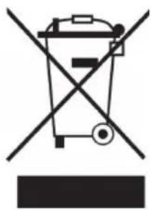
Symbol of a trash bin crossed with a diagonal line, no text or labels presentAccording to the European waste regulation 2012/19/EU this symbol on the product or on its packaging indicates that this product may not be treated as household waste. Instead it should be taken to the appropriate collection point for the recycling of electrical and electronic equipment. By ensuring this product is disposed of correctly, you will help prevent potential negative consequences for the environment and human health, which could otherwise be caused by inappropriate waste handling of this product. For more detailed information about recycling of this product, please contact your local council or your household waste disposal service.

bar
| Category | Value | |---|---| | Category 1 | 100 | | Category 2 | 100 | | Category 3 | 100 | | Category 4 | 100 | | Category 5 | 100 | | Category 6 | 100 | | Category 7 | 100 | | Category 8 | 100 | | Category 9 | 100 | | Category 10 | 100 | | Category 11 | 100 | | Category 12 | 100 | | Category 13 | 100 | | Category 14 | 100 | | Category 15 | 100 | | Category 16 | 100 | | Category 17 | 100 | | Category 18 | 100 | | Category 19 | 100 | | Category 20 | 100 | | Category 21 | 100 | | Category 22 | 100 | | Category 23 | 100 | | Category 24 | 100 | | Category 25 | 100 | | Category 26 | 100 | | Category 27 | 100 | | Category 28 | 100 | | Category 29 | 100 | | Category 30 | 100 | | Category 31 | 100 | | Category 32 | 100 | | Category 33 | 100 | | Category 34 | 100 | | Category 35 | 100 | | Category 36 | 100 | | Category 37 | 100 | | Category 38 | 100 | | Category 39 | 100 | | Category 40 | 100 | | Category 41 | 100 | | Category 42 | 100 | | Category 43 | 100 | | Category 44 | 100 | | Category 45 | 100 | | Category 46 | 100 | | Category 47 | 100 | | Category 48 | 100 | | Category 49 | 100 | | Category 50 | 100 | | Category 51 | 100 | | Category 52 | 100 | | Category 53 | 100 | | Category 54 | 100 | | Category 55 | 100 | | Category 56 | 100 | | Category 57 | 100 | | Category 58 | 100 | | Category 59 | 100 | | Category 60 | 100 | | Category 61 | 100 | | Category 62 | 100 | | Category 63 | 100 | | Category 64 | 100 | | Category 65 | 100 | | Category 66 | 100 | | Category 67 | 100 | | Category 68 | 100 | | Category 69 | 100 | | Category 70 | 100 | | Category 71 | 100 | | Category 72 | 100 | | Category 73 | 100 | | Category 74 | 100 | | Category 75 | 100 | | Category 76 | 100 | | Category 77 | 100 | | Category 78 | 100 | | Category 79 | 100 | | Category 80 | 100 | | Category 81 | 100 | | Category 82 | 100 | | Category 83 | 100 | | Category 84 | 100 | | Category 85 | 100 | | Category 86 | 100 | | Category 87 | 100 | | Category 88 | 100 | | Category 89 | 100 | | Category 90 | 100 | | Category 91 | 100 | | Category 92 | 100 | | Category 93 | 100 | | Category 94 | 100 | | Category 95 | 100 | | Category 96 | 100 | | Category 97 | 100 | | Category 98 | 100 | | Category 99 | 100 | | Total (Total) = [sum of two separate bars] * [sum of the bars] * [values from the 'data' table in the 'data' table] * [values from the 'data' table in the 'data' table] * [values from the 'data' table in the 'data' table] * [values from the 'data' table in the 'data' table] * [values from the 'data' table in the 'data' table] * [values from the 'data' table in the 'data' table] * [values from the 'data' table in the 'data' table] * [sum of the bars] * [values from the 'data' table] * [sum of the bars] * [values from the 'data' table] * [sum of the bars] * [values from the 'data' table] * [sum of the bars] * [values from the 'data' table] * [sum of the bars] * [sum of the bars] * [values from the 'data' table] * [sum of the bars] * [sum of the bars] * [values from the 'data' table] * [sum of the bars] * [sum of the bars] * [values from the 'data' table] * [sum of the bars] * [sum of the bars] * [values from the 'data' table] * [sum of the bars] * [total (Total) = [sum of these bars] * [values from the 'data' table] * [sum of the bars] * [values from the 'data' table] * [values from the 'data' table] * [sum of the bars] * [sum of the bars] * [values from the 'data' table] * [sum of the bars] * [sum of the bars] * [values from the 'data' table] * [sum of the bars] * [sum of the bars]KLARSTEIN NIEI SRA T EIN NIEI SRA T K LARS KLARSTEIN NIEI SRA T EIN NIEI SRA T K LARS KLARSTEIN NIEI SRA T EIN NIEI SRA T K LARS KLARSTEIN NIEI SRA T