
DM S160 - Diamond drill HUSQVARNA - Free user manual and instructions
Find the device manual for free DM S160 HUSQVARNA in PDF.

| Product Type | Diamond Drill |
| Brand | HUSQVARNA |
| Model | DM S160 |
| Rated Voltage | 230 V / 100-120 V (single phase) |
| Rated Power | 1560 W |
| Rated Current | 6 A (230 V) / 13 A (100-120 V) |
| Max. Drilling Diameter | 120 mm (with stand) |
| No-Load Spindle Speed | Green 1: 1100 rpm, Green 2: 980 rpm, Green 3: 840 rpm |
| Spindle Speed under Load | Yellow: 700 rpm, Red: 640 rpm |
| Motor Weight | 5.9 kg |
| Stand Weight (according to version) | DMS160 A: 10.5 kg; AT: 12 kg; Gyro: 31.4 kg |
| Stand Height | DMS160 A: 840 mm; AT: 900 mm; Gyro: 1900 to 3100 mm |
| Feed Stroke | 600 mm |
| Cooling | Water |
| Spindle Thread | Int. 1/2" R |
| Water Connection | G 1/4" |
| Safety Equipment | PRCD residual current device, mechanical slip coupling (SMC), double insulation, LCS load indicator |
| Routine Maintenance | Daily check of screws, cable, cooling openings; lubricate stand; replace carbon brushes if < 6 mm |
| Available Accessories | I/U extension modules, water collector, underpressure plate, expansion fastening, tool kits |
| Sound Level (power) | 102 dB(A) measured, 103 dB(A) guaranteed |
| Vibration Level | < 2.5 m/s² (handle) |
Frequently Asked Questions - DM S160 HUSQVARNA
User questions about DM S160 HUSQVARNA
0 question about this device. Answer the ones you know or ask your own.
Ask a new question about this device
Download the instructions for your Diamond drill in PDF format for free! Find your manual DM S160 - HUSQVARNA and take your electronic device back in hand. On this page are published all the documents necessary for the use of your device. DM S160 by HUSQVARNA.
USER MANUAL DM S160 HUSQVARNA
natural_image
Icon of an open book inside a circle (no text or symbols)
Operator's manual
Please read the operator's manual carefully and make sure you understand the instructions before using the machine.

natural_image
Simple line drawing of a mechanical clamp or lever (no text or symbols)GB ES DE FR
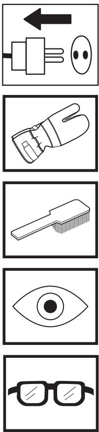
Symbols on the machine:
WARNING! The machine can be a dangerous tool if used incorrectly or carelessly, which can cause serious or fatal injury to the operator or others.
Please read the operator's manual carefully and make sure you understand the instructions before using the machine.
Always wear:
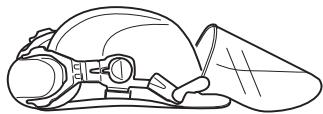
• Approved protective helmet
• Approved hearing protection
• Protective goggles or a visor
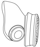
- Breathing mask
This product is in accordance with applicable EC directives.
Environmental marking. Symbols on the product or its packaging indicate that this product cannot be handled as domestic waste. It must instead be submitted to an appropriate recycling station for the recovery of electrical and electronic equipment.
By ensuring that this product is taken care of correctly, you can help to counteract the potential negative impact on the environment and people that can otherwise result through the incorrect waste management of this product.
For more detailed information about recycling this product, contact your municipality, your domestic waste service or the shop from where you purchased the product.
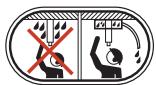
Ensure that water cannot leak into the machine when drilling in the ceiling. Use an appropriate water collector and cover the machine in plastic, but do not cover the air intakes and air outlets.
The drilling machine must be suitable and designed for the size of drill bit. The max drill bit diameter is stated on the machine.
Use a drill suitable for the work.
Load/power indication (LCS-Load control system).
Check that the ceiling is strong enough. The ceiling should be solid.


text_image
CE


Make sure that the fork grips in the inner ear. Tighten using a suitable spanner.
Lock the nut using a 30 mm spanner. Check the lock nut on the L-handle. Make sure that it is tightened.
WARNING! Dust forms when drilling, which can cause injuries if inhaled. Use an approved breathing mask. Always provide for good ventilation.
Other symbols/decals on the machine refer to special certification requirements for certain markets.

Symbols in the operator's manual:
Inspection and/or maintenance should be carried out with the motor switched off and the plug disconnected.
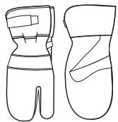
Always wear approved protective gloves.
Regular cleaning is required.
Visual check.
Protective goggles or a visor must be worn.
Contents
KEY TO SYMBOLS
Symbols on the machine: 2
Symbols in the operator's manual: 2
CONTENTS
Contents 3
WHAT IS WHAT?
What is what on the drilling machine? 4
WHAT IS WHAT?
What is what on the stand? 5
SAFETY INSTRUCTIONS
Steps before using a new drilling machine 6
Personal protective equipment 6
Machine's safety equipment 7
Checking, maintaining and servicing the machine's safety equipment 7
General safety precautions 7
PRESENTATION
Drill motor and stand 8
Drill motor DMS160 8
Stand DMS160 8
ASSEMBLY
Assembling the stand - DMS160 A/AT 9
Assembling the stand - DMS160 Gyro 9
STARTING AND STOPPING
Before starting 12
Starting 12
Stopping 12
WORKING TECHNIQUES
General working instructions 13
Using the machine 14
MAINTENANCE
Maintenance of the drill motor 15
Stand maintenance 16
TECHNICAL DATA
Drill motor DMS160 17
Stand DMS160 18
EC-declaration of conformity 18
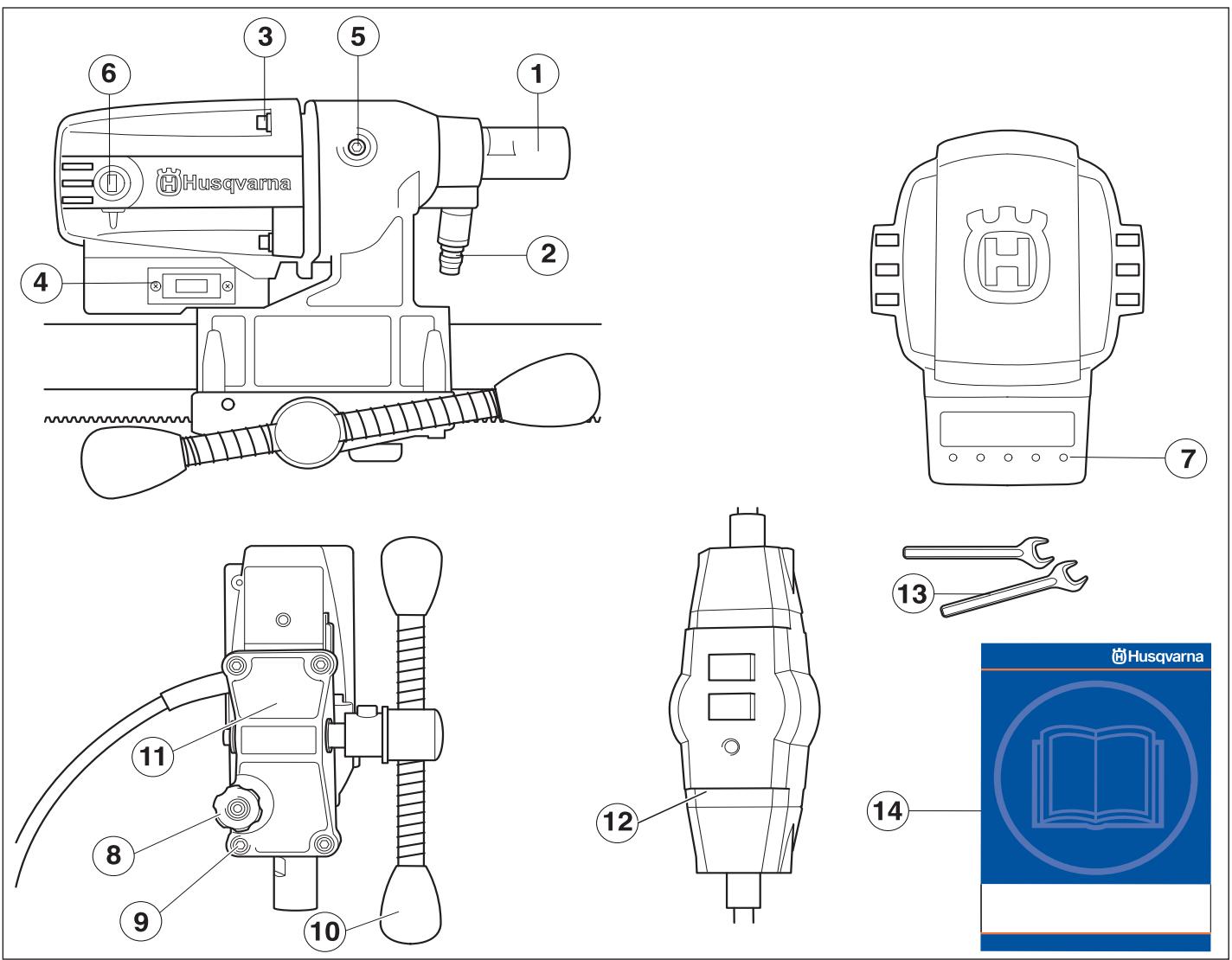
What is what on the drilling machine?
1 Drill spindle
2 Water connector
3 Screws holding together the gearbox and the motor.
4 Switch
5 Cover for slip clutch (SMC)
6 Carbon brush cover
7 Load/power indication (LCS-Load control system).
8 Locking knob
9 Screws (4) for feeder rear section and gearbox
10 Feeder handle
11 Feeder rear section
12 PRCD Earth-fault breaker
13 Spanners
14 Operator's manual
text_image
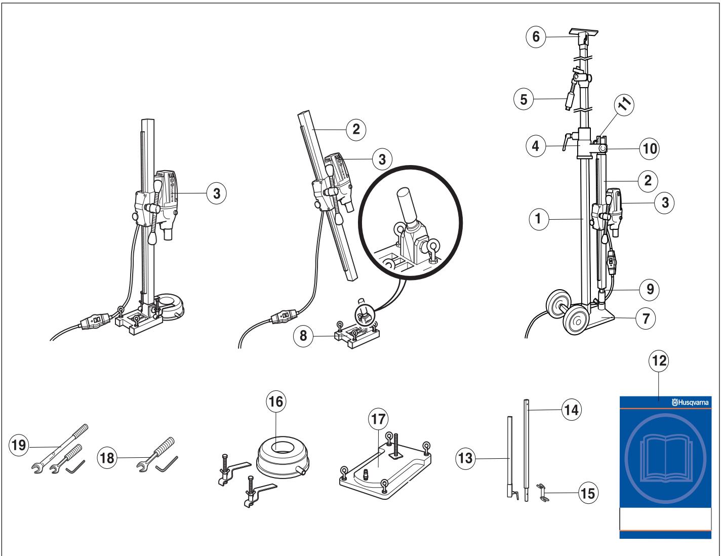
Technical diagram of a mechanical testing setup with numbered components and a Husqvarna book cover.What is what on the stand?
1 Telescopic support column 40
2 Drill column
3 Drill motor DMS160
4 Wall rail
5 Support column/locking mechanism
6 Ceiling plate
7 Base plate (GB 40 T) with transport wheels
8 Expander angle base plate
9 Column screw and lock screw
10 Locking nut
11 L-handle
12 Operator's manual
13 Extension module U (Available as an accessory.)
14 Extension module I (Available as an accessory.)
15 Expansion attachment (Available as an accessory.)
16 Water collector (Available as an accessory.)
17 Vacuum plate (Available as an accessory.)
18 Tool kit DMS160 AT
19 Tool kit DMS160 Gyro
Steps before using a new drilling machine
- Read through the operating instructions carefully before you begin using the machine.
- This machine is designed for and intended for drilling concrete, brick and different stone materials. All other use is improper.
- The machine is intended for use in industrial applications by experienced operators.
- Check the assembly of the drill, see the section changing the drill bit.
- Check that the cord and extension cord are intact and in good condition.
- Keep the workplace tidy. Disorder leads to accident risks.
Always use common sense
It is not possible to cover every conceivable situation you can face when using a drilling machine. Always exercise care and use your common sense. Avoid all situations which you consider to be beyond your capability. If you still feel uncertain about operating procedures after reading these instructions, you should consult an expert before continuing. Do not hesitate to contact your dealer or us if you have any more questions about the use of the drilling machine. We will willingly be of service and provide you with advice as well as help you to use your drilling machine both efficiently and safely.
Let your Husqvarna dealer check the drilling machine regularly and make essential adjustments and repairs.
All information and all data in the Operator's Manual were applicable at the time the Operator's Manual was sent to print.

WARNING! Under no circumstances may the design of the machine be modified without the permission of the manufacturer. Always use genuine accessories. Non-authorized modifications and/or accessories can result in serious personal injury or the death of the operator or others.

WARNING! The use of products such as cutters, grinders, drills, that sand or form material can generate dust and vapours which may contain hazardous chemicals. Check the nature of the material you intend to process and use an appropriate breathing mask.
Personal protective equipment

WARNING! You must use approved personal protective equipment whenever you use the machine. Personal protective equipment cannot eliminate the risk of injury but it will reduce the degree of injury if an accident does happen. Ask your dealer for help in choosing the right equipment.
- Protective helmet
- Hearing protection
• Protective goggles or a visor
- Breathing mask
• Heavy-duty, firm grip gloves.
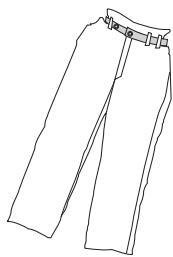
- Tight-fitting, heavy-duty and comfortable clothing that permits full freedom of movement.
natural_image
Line drawing of a pair of trousers with a belt buckle (no text or symbols)• Boots with steel toe-caps and non-slip sole.

• Always have a first aid kit nearby.

Machine's safety equipment
This section describes the machine's safety equipment, its purpose, and how checks and maintenance should be carried out to ensure that it operates correctly. See the "What is what?" section to locate where this equipment is positioned on your machine.

WARNING! Never use a machine that has faulty safety equipment! Safety equipment must be inspected and maintained. See instructions under the heading Checking, maintaining and servicing the machine's safety equipment. If your machine does not pass all the checks, take it to a service workshop for repair.
Checking, maintaining and servicing the machine's safety equipment

IMPORTANT! All servicing and repair work on the machine requires special training. This is especially true of the machine's safety equipment. If your machine fails any of the checks described below you must contact your service agent. When you buy any of our products we guarantee the availability of professional repairs and service. If the retailer who sells your machine is not a servicing dealer, ask him for the address of your nearest service agent.
Switch
The power switch should be used to start and stop the machine.
Checking the power switch
- Start the machine by pressing the power switch.
- Shut down the machine by pressing the power switch.
- A defective power switch should be replaced by an authorized service workshop.
General safety precautions
- Do not use the drilling machine without first reading and understanding the contents of this Operator's Manual.

WARNING! There is always a risk of shocks from electrically powered machines. Avoid unfavourable weather conditions and body contact with lightning conductors and metal objects. Always follow the instructions in the Operator's manual to avoid damage.

WARNING! There is always a risk of crush injuries when working with products containing moving parts. Wear protective gloves to avoid body injuries.
- Never use the machine if you are tired, if you have drunk alcohol, or if you are taking medication that could affect your vision, your judgement or your co-ordination.
- Wear personal protective equipment. See instructions under the heading Personal protective equipment.
- Never carry the machine by means of the cord and never pull out the plug by pulling the cord. Keep all cords and extension cords away from water, oil and sharp edges. Make sure the cord is not pinched in doors, fences or the like. Otherwise it can cause the object to become live.
- Check that the cord and extension cord are intact and in good condition. Use an extension cord intended for outdoor use. Never use the machine if the cord is damaged, hand it in to an authorized service workshop for repair.
- Do not use an extension cord while it is rolled up to avoid overheating.

- The machine should be connected to an earthed outlet socket.
- Check that the mains voltage corresponds with that stated on the rating plate on the machine.
- Never use a machine that is faulty. Carry out the checks, maintenance and service instructions described in this manual. Some maintenance and service measures must be carried out by trained and qualified specialists. See instructions under the heading Maintenance.
- Never allow anyone else to use the machine without first ensuring that they have understood the contents of the operator's manual.
- People and animals can distract you causing you to lose control of the machine. For this reason, always remain concentrated and focused on the task.
- Be careful as clothing, long hair, and jewellery can get caught in moving parts.
Transport and storage
Do not store or transport the drilling machine with the drill bit fitted in order to protect your drilling machine and drill bits from damage.
Store the drilling machine in a lockable area so that it is out of reach of children and unauthorised persons.
Store the drilling machine and stand in dry and frost free conditions.
Drill motor and stand
It is our wish that you will be satisfied with your product and that it will be your companion for a long time. Think of this operator's manual as a valuable document. By following its content (using, service, maintenance etc) the life span and the second-hand value of the machine can be extended. If you will sell this machine, make sure that the buyer will get the operator's manual.
A purchase of one of our products gives you access to professional help with repairs and services whenever this may be necessary. If the retailer who sells your machine is not one of our authorised dealers, ask him for the address of your nearest service workshop.
Husqvarna Construction Products has a policy of continuous product development. Husqvarna reserves the right to modify the design and appearance of products without prior notice and without further obligation introduce design modifications.
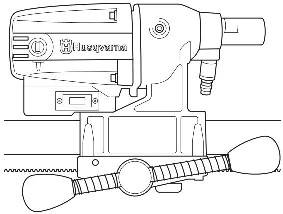
Drill motor DMS160
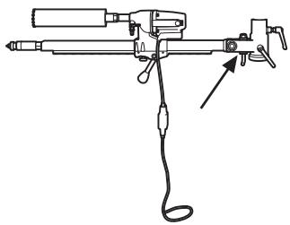
natural_image
Technical line drawing of a Husqvarna electric drill press with attached trigger mechanism (no text or symbols)- DMS160 is an electric drill, intended for drilling concrete, brick and various stone materials.
- The drilling machine has a modular design and is easy to assemble.
- The machine has a speed range for drill bits with a diameter( ) of 120 mm / 4.75 In.
- The design of the slip clutch (SMC-Slide Mechanical Clutch) gives the greatest power output and it can be adjusted from outside.
- The machine is intended for stand mounted drilling.
• The machine is water cooled. - The machine is double insulated and has power indicators.
- The machine works at its best if not overloaded, let the maximum yellow LED on the load/power indicator (LCS-Load Control System) be on. Max. 10 minutes max. load the machine must then be run without a load for 2 minutes.
Stand DMS160
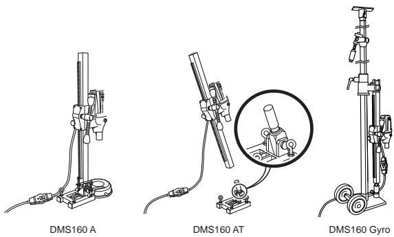
DMS160 A/AT
The stands are secured using expanding screws.
- A water collector and vacuum plate are available as accessories to suck the stand into place.
natural_image
Technical line drawings of mechanical components including a bracket, clamps, and a circular housing (no text or symbols)DMS160 AT
- DMS160 AT has a modular design that permits angle drilling and a rotation function.
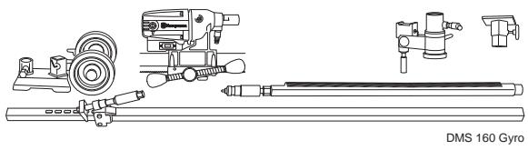
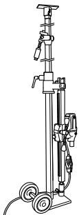
DMS160 Gyro
- DMS160 Gyro has a modular design with telescopic stand to secure the drill motor.
- The telescopic support column has a maximum length of 3.1 metres, but can be extended an additional 0.75 metres using an extension module.
• A maximum of one extension module may be used. - Only one spanner (24/30 mm) and an allen key (8 mm) are required to change the settings.

The drill column can be variably adjusted through 360^ .
• The transport wheels can be removed.
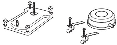
Assembling the stand - DMS160 A/AT
natural_image
Technical line drawing of mechanical clamps and a bracket assembly (no text or symbols)DMS160 A/AT
- Drill holes (15 mm) in the floor or in the wall and knock in the expander bolts.
20 Bolt down the base plate. Check carefully that the expander is secured correctly.
natural_image
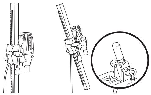
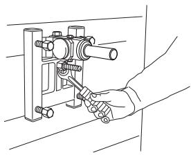
Line drawing of a hand using a screwdriver to adjust or install a mechanical component (no text or symbols present)DMS160 AT
- The drill column is mounted on the base plate's angle bracket. Tighten the lock screw with an 8 mm allen key. The drill column can be turned through 360° and locked variably in each position using a locking screw (8 mm allen key)
natural_image
Line drawing of a hand using a handheld tool to adjust or install a mechanical component (no text or symbols present)- The drill column is set at the required angle by tightening the nut using a 24 mm spanner. If the vacuum plate is used, make sure the support surface is not porous and can loosen from the floor or the wall. Make sure that the vacuum pump has sufficient power to secure the vacuum plate. A suitable vacuum motor is Husqvarna VP200.

natural_image
Technical line drawing of a mechanical linkage assembly (no text or symbols)
WARNING! The vacuum plate must never be used for ceiling drilling. Careless or incorrect use can result in serious or fatal injury to the operator or others.
Assembling the stand - DMS160 Gyro
natural_image
Technical line drawing of a mechanical assembly with no visible text or symbols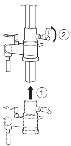
text_image
Technical diagram showing mechanical assembly with labeled parts and directional arrows indicating motion or movement.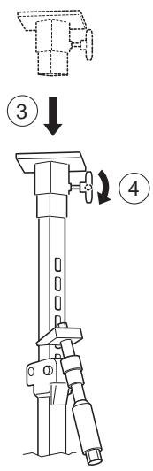
text_image
Technical diagram showing a mechanical assembly with numbered steps and directional arrows indicating motion or assembly.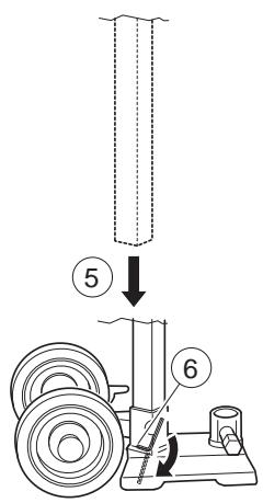
text_image
Diagram showing a mechanical setup with labeled parts and directional arrows, likely illustrating a turning or positioning process.
text_image
Technical diagram of a mechanical device with numbered parts and directional arrows indicating motion or assembly.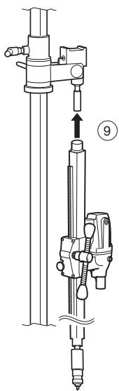
text_image
Technical diagram showing a mechanical device with labeled component 9 and directional arrow indicating movement or force.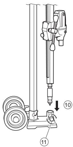
text_image
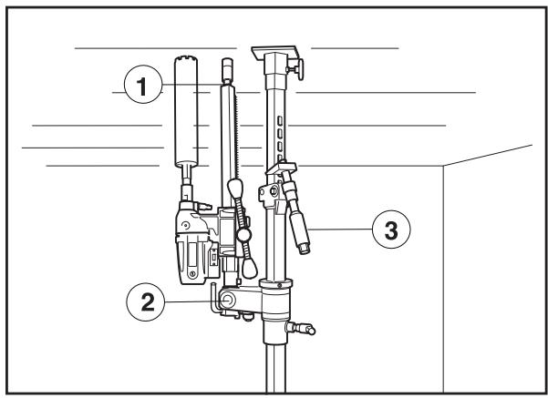
Technical diagram of a mechanical drilling setup with labeled components and directional arrowsDrilling in walls

text_image
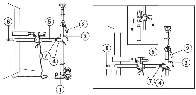
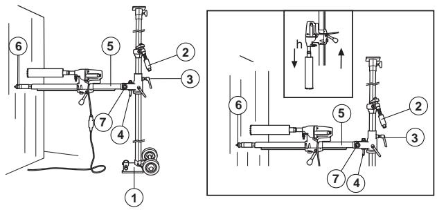
Technical diagram showing mechanical assembly with numbered components and a close-up view of a device with labeled parts.1 Base plate with locking screw.
2 Column screw and lock screw
3 Locking knob
4 L-handle
5 Drill column
6 Column screw and lock screw
7 Locking nut
8 Drill motor DMS160
- Place the base plate at a drill column's length from the wall. The support column screw should be screwed in. When drilling is to be performed at a height greater than 1.5 metres, the heavier outer tube should be turned upwards and vice versa when drilling below 1.5 metres. Check that the support column is clamped in the base plate with the locking screw.
- Clamp the telescopic column support against the ceiling. Choose the closest hole in the holed inner tube. Clamp using the support column handle and screw the last bit using a 24 mm spanner. Do not clamp too tight.
- Loosen the locking handle and rotate the drill column. Fold down the drill column using the L-handle.
• Fit the drill motor DMS160 on the drill column. - Then turn back the drill column with the drill motor to the desired position against the wall. Lock the locking handle.
- Angle back and fold up the drill column, secure with the L-handle and nut. When angle drilling, loosen the L-handle and set the drill column at the required angle by tightening the nut using a 30 mm spanner.
- Check the position of the drill bit. Screw in the support column screw against the wall to secure the drill column. Secure with a locking nut, 30 mm. Use a wooden batten as packing. The drill column can be turned through 360° and locked variably in each position using a locking screw (8 mm allen key)
- The expander attachment can be used to provide additional anchorage of the drill column. The attachment is adjusted against the support column screw and is secured on the wall with an expansion bolt. Secure with a locking nut, 30 mm.
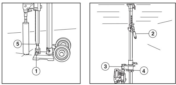
Drilling in the floor
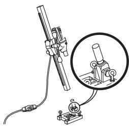
text_image
Technical diagram showing mechanical assembly with numbered components and labeled parts1 Locking screw
2 Column screw and lock screw
3 Locking knob
4 L-handle
5 Locking screw
- Fold down the drill column using the L-handle.
• Make sure that the support column enters the lock sleeve.
- Tighten the locking nut with a 30 mm key and lock the locking handle.
natural_image
Technical line drawing of a mechanical device with a cable and lever (no text or symbols)- Place the stand in the required position.
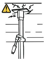
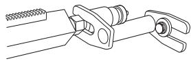
6 Lock the support column in the lock sleeve with the locking screw and the nut. Tighten using the 24 and 30 mm spanners. - Clamp the telescopic support column against the ceiling with the support column mechanism. Tighten the last bit using a 24 mm spanner, do not tighten too tight. The telescopic support column has a maximum length of 3.1 metres, but can be extended an additional 0.75 metres using an extension module.
Drilling in the ceiling
text_image
Technical diagram of a mechanical device with numbered parts labeled 1, 2, and 3.1 Column screw and lock screw
2 Locking nut
3 Column screw and lock screw
- Place the stand in the required position.
- Check that the support column screw in the drill column is screwed in. Fold up and lock the drill column in the vertical position with the locking nut.
- Check that the drill bit is in the right position. Clamp the telescopic support column against the ceiling with the support column mechanism.
- Screw in the support column screw against the ceiling to secure the drill column. Secure with a locking nut, 30 mm. Use a wooden batten as packing.
- The expander attachment can be used to provide additional anchorage of the drill column. (Available as an accessory.) The attachment is adjusted against the support column screw and is secured on the wall with an expansion bolt. Secure with a locking nut, 30 mm.

WARNING! The vacuum plate must never be used for ceiling drilling. Careless or incorrect use can result in serious or fatal injury to the operator or others.
STARTING AND STOPPING
Before starting


WARNING! Note the following before starting:
The machine should be connected to an earthed outlet socket.
Check that the mains voltage corresponds with that stated on the rating plate on the machine. Keep people and animals well away from the working area.

WARNING! Before drilling, check that all locking screws are tightened well.
Serious accidents can occur if the concrete core remains in the drill when backing out the drill motor/drill from the floor, wall or ceiling.
Make sure that:
- The switch is undamaged. If not, the switch must be replaced by an authorised repairman.
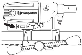
natural_image
Technical line drawing of a mechanical device with no visible text or symbols- The machine and its equipment are correctly installed:
- The drill is secured properly.
- The stand is firmly attached.
- Secure the machine on the stand using a suitable method.
- Wear personal protective equipment. See instructions under the heading Personal protective equipment.
• Water cooling is connected to the machine.
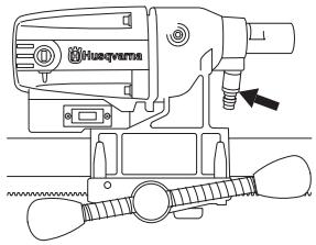
natural_image
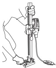
Technical line drawing of a mechanical device with no visible text or symbolsDrilling in the ceiling

WARNING! The vacuum plate must never be used for ceiling drilling.
Use a water collector to avoid water penetrating into the machine. The machine must be covered with plastic or the like in order to prevent water penetrating into the machine, but do not cover the air intakes and air outlets.
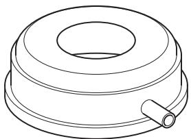
natural_image
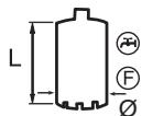
Line drawing of a cylindrical mechanical component with a central hole and a side pipe (no text or symbols)
WARNING! A maximum of one extension module may be used.
Check that no one on the floor below can be injured by falling concrete cores.
Starting
• Turn on the water cooling.
- Press in the switch fully.
- Start to feed the drill bit with the help of the feed handle.
Stopping

WARNING! The drill bit continues to rotate for a while after the motor has been switched off. Do not stop the drill bit with your hands. Personal injuries can occur.
Shut down the machine by pressing the power switch.
Cooling
Run the machine unloaded for a minute or two to cool the motor.
General working instructions


WARNING! This section takes up the basic safety precautions for working with the drilling machine. This information is never a substitute for professional skills and experience. If you encounter a situation where you are uncertain how to proceed you should ask an expert. Contact your dealer, service agent or an experienced drilling machine user. Do not attempt any task that you feel unsure of!

WARNING! Overexposure to vibration can lead to circulatory damage or nerve damage in people who have impaired circulation. Contact your doctor if you experience symptoms of overexposure to vibration. Such symptoms include numbness, loss of feeling, tingling, pricking, pain, loss of strength, changes in skin colour or condition. These symptoms normally appear in the fingers, hands or wrists. These symptoms may be increased in cold temperatures.
- Do not use the machine in bad weather, such as dense fog, rain, strong wind, intense cold, etc. Working in bad weather is tiring and can lead to dangerous conditions, e.g. slippery surfaces.
- Never start to work with the power cutter before the working area is clear and you have a firm foothold. Look out for any obstacles with unexpected movement. Ensure when cutting that no material can become loose and fall, causing operating injury.
- Remain at a distance from the drill bit when the motor is running.
- Ensure that the working area is sufficiently illuminated to create a safe working environment.
- Make sure that no pipes or electrical cables are routed in the area to be drilled.
- Ensure the cord is behind you when you start to use the machine so that the cord will not be damaged.
- Never leave the machine unsupervised with the motor running. A rotating drill bit can entail a risk of serious injury.
• Always unplug the machine during longer work breaks. - Do not overload the machine. Overloading can damage the machine.
- Keep tools sharp and clean in order to enable safer work.
-
Always check the rear side of the surface where the drill bit will emerge when drilling right through. Secure and cordon off the area and make sure that no one can be injured or material damaged.
• Always switch off the machine before you move it. -
Never work alone, always ensure there is another person close at hand. Apart from being able to receive help to assemble the machine, you can also get help if an accident should occur.
- Keep all parts in good working order and ensure that all fixtures are properly tightened.
Using the machine
- Keep your hands at a safe distance from the drill spindle and drill bit when the machine is running.
- Keep an eye open for oil or water leakage.
Drilling outdoors
Always use extension cables that are approved for outdoor use.
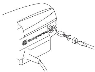
Changing the drill bit
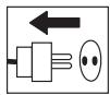
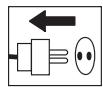
1 Pull out the plug.
2 Get:
- The new drill bit.
- The supplied open-ended spanners, size 24 mm and 32 mm.
- Water-resistant grease.
3 Remove the old drill bit using the open-ended spanners.
4 Apply water-resistant grease to the thread of the new drill bit.
5 Attach the drill bit using the open-ended spanners.
natural_image
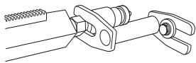
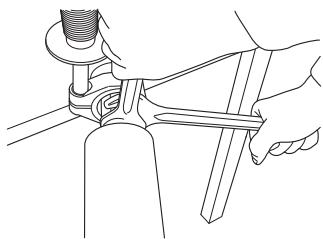
Line drawing of a hand using a tool to lift or adjust a bottle (no text or symbols present)Slip clutch (SMC)
The machine is equipped with a mechanical slip clutch (SMC).
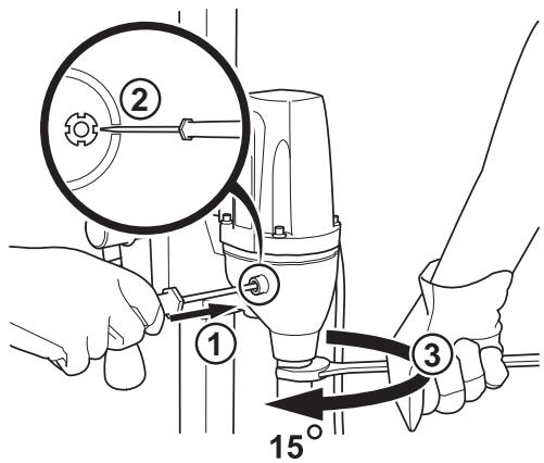
Tension the slip clutch as follows:
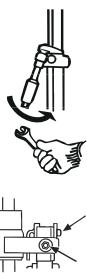
- Loosen the cover for the slip clutch.
text_image
Technical diagram showing mechanical assembly steps with numbered annotations and a 15° angle indicator- Carefully lock the hook nut using a flat wide screwdriver in one of the hook nut's four notches.
- Turn the drill spindle with a 27 mm open-ended spanner 15 degrees.
Remove the screwdriver and refit the cover on the slip clutch.
Load/power indication (LCS-Load control system).
The machine works at its best if not overloaded, let the maximum yellow LED on the load/power indicator (LCS-Load Control System) be on. Max. 10 minutes max. load the machine must then be run without a load for 2 minutes.
Maintenance of the drill motor
IMPORTANT! Inspection and/or maintenance should be carried out with the motor switched off and the plug disconnected.
The lifetime of your machine can be extended considerably if it is used, cared for and maintained in the proper manner.
Cleaning
- Keep the machine and drill bit clean in order for drilling to be carried out safely.
natural_image
Line drawing of a hand operating a mechanical clamp or tool (no text or symbols present)- In order for the machine to always be cooled sufficiently the cooling air openings must be kept clear and clean. Blow down the machine regularly with compressed air.
Electrical Feed

WARNING! Never use damaged cables that can cause serious, even fatal, personal injuries.
Check that the cord and extension cord are intact and in good condition. Never use the machine if the cord is damaged, hand it in to an authorized service workshop for repair.
Repairs
IMPORTANT! All types of repairs may only be carried out by authorised repairmen. This is so that the operators are not exposed to great risks.
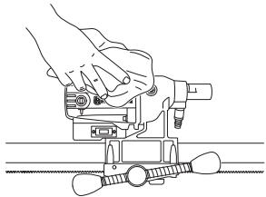
Replacing the motor and the gearbox
1 Secure the machine with drill spindle downwards in a vice or the like.
2 Remove the cover for the carbon brushes using a flat wide screwdriver.
natural_image
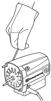
Line drawing of a device with a connector and cable, no text or symbols present3 Carefully remove the carbon brushes.
4 Unscrew the four screws holding together the motor and gearbox.
5 Loosen the ground cable from the gearbox cover (only applies to 230V).
6 Carefully disassemble the machine.
7 Replace the module that needs to be replaced. Use Castrol MS3 Molybdenum grease in the gearbox.
natural_image
Line drawing of a hand using a screwdriver to lift a motor (no text or symbols)8 Assemble the motor with the gearbox.
9 Replace the screws.
10 Screw on the brush cover.
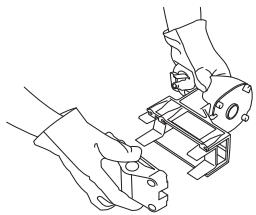
Changing the rear section
1 Loosen the four screws and the locking knob on the rear of the drill.
2 Replace the two slide plates when the rear section is to be replaced.
natural_image
Line drawing of two hands assembling or adjusting a mechanical component (no text or symbols)3 Bolt together the rear section using the four screws. Screw in the locking knob.
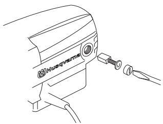
Replacing the carbon brushes
The carbon brushes must be removed and checked regularly. Weekly if the machine is used daily or at longer intervals if the machine is used more seldom. The area of wear should be even and undamaged.
Both carbon brushes must always be replaced as a pair, but one at a time. Do as follows:
1 Remove the cover for the carbon brushes using a flat wide screwdriver.
natural_image
Line drawing of a device with a connector and cable, no text or symbols present2 Carefully remove the carbon brushes. The carbon brushes must be replaced if there is less than 6 mm remaining on the brushes.
3 Fit new carbon brushes.
4 Screw on the brush cover.
5 Let the machine idle for 10 minutes to run in the new carbon brushes.
Daily maintenance
1 Check that nuts and screws are tight.
2 Check that the power switch unit works smoothly.
3 Clean the outside of the machine.
4 Check and clean the cooling air openings.
5 Check that the cord and extension cord are intact and in good condition.
Stand maintenance
Cleaning and lubrication
IMPORTANT! Remove the drill motor. For maintenance of the drill motor see maintenance of the drill motor.
- It is important that the drill stand is kept clean for functionality to be maintained.
- Clean the stand using a high pressure washer and then wipe dry.
- Lubricate the moving parts on the stand. Apply standard grease to counteract corrosion on the contact surfaces.
Repairs
IMPORTANT! All types of repairs may only be carried out by authorised repairmen. This is so that the operators are not exposed to great risks.
Daily maintenance
1 Check that nuts and screws are tight.
2 Clean the outside of the machine.
TECHNICAL DATA
Drill motor DMS 160
| Electric motor | Single-phase |
| Rated voltage, V | 230/100-120 |
| Rated output, W | 1560 |
Rated current, A
| 230 V | 6A |
| 100-120 V | 13A |
| Weight, kg | 5,9 |
Diameter drill bit, mm
| Max. diameter of the drill bit, with stand | 120 mm (4.7") |
| Spindle thread | Int. 1/2" R |
| Water connector | G 1/4" |
Spindle speed, idle, rpm
| Green 1 | 1100 |
| Green 2 | 980 |
| Green 3 | 840 |
Spindle speed, rpm
| Yellow | 700 |
| Red | 640 |
Noise emissions (see note 1)
| Sound power level, measured dB(A) | 102 |
| Sound power level, guaranteed LWA dB(A) | 103 |
Sound levels (see note 2)
| Sound pressure level at the operators ear, dB(A) | 89 |
Vibration levels (see note 3)
| Handle, m/s ^2 | <2,5 |
Note 1: Noise emissions in the environment measured as sound power ( L_WA ) in conformity with EN 12348.
Note 2: Noise pressure level according to EN 12348. Reported data for noise pressure level has a typical statistical dispersion (standard deviation) of 1.0 dB(A).
Note 3: Vibration level according to EN 12348. Reported data for vibration level has a typical statistical dispersion (standard deviation) of 1 m/s^2 .
TECHNICAL DATA
Stand DMS 160
Height, mm
| DMS 160 A height, mm | 840 |
| DMS 160 AT height, mm | 900 |
| DMS 160 Gyro height, mm | 1900-3100 |
| Stroke, mm | 600 |
| Max. drill bit diameter (mm) | 120 |
Weight, kg
| DMS 160 A | 10,5 |
| DMS 160 AT | 12 |
| DMS 160 Gyro | 31,4 |
| Tool kit DMS 160 AT | 0,3 |
| Tool kit DMS 160 Gyro | 0,8 |
Weight, kg (extra accessory)
| Vacuum plate | 2,5 |
| Water collector | 0,7 |
| Extension module I | 2,9 |
| Extension module U | 2,9 |
| Expansion attachment | 0,8 |
EC-declaration of conformity
(Applies to Europe only)
Husqvarna AB, SE-433 81 Göteborg, Sweden, tel: +46-31-949000, declares under sole responsibility that drilling machine and stand Husqvarna DMS 160 drill motor, DMS 160 A/AT/Gyro from 2010's serial number and onward (the year is stated in plain text on the type plate plus a subsequent serial number) conform with the regulations in the COUNCIL'S DIRECTIVE:
• of May 17, 2006 "relating to machinery" 2006/42/EC
• of December 15, 2004 "relating to electromagnetic compatibility" 2004/108/EC.
• of December 12, 2006 "relating to electrical equipment" 2006/95/EC.
The following standards have been applied: EN ISO 12100:2003, EN 55014-1:2006, EN 55014-2/A1:2001, EN 61000-3-2:2006, EN 61000-3-3/A1/A2:2005, EN 12348/A1:2009.
Göteborg December 29, 2009

text_image
flunkHenric Andersson
Vice President, Head of Power Cutters and Construction Equipment
Husqvarna AB
(Authorized representative for Husqvarna AB and responsible for technical documentation.)
text_image
Technical diagram of a mechanical testing setup with numbered components and a Husqvarna book cover.natural_image
Line drawing of a pair of trousers with a belt buckle (no text or symbols)natural_image
Technical line drawing of a Husqvarna electric drill press with attached trigger mechanism (no text or symbols)natural_image
Technical line drawings of mechanical components including a bracket, clamps, and a circular housing (no text or symbols)DMS160 AT
natural_image
Line drawing of a hand using a tool to adjust or install a mechanical component (no text or symbols present)DMS160 AT
natural_image
Line drawing of a hand using a handheld tool to lift a cylindrical component (no text or symbols)natural_image
Mechanical assembly diagram showing a lever mechanism with no visible text or symbols
natural_image
Technical line drawing of a mechanical assembly with no visible text or symbols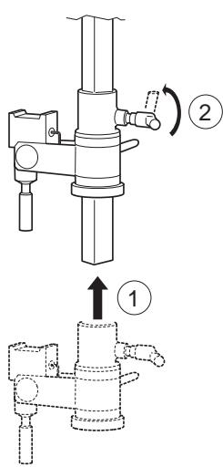
text_image
Technical diagram showing mechanical assembly steps with numbered annotations indicating motion directions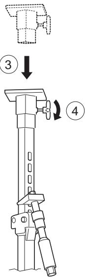
text_image
Technical diagram showing a mechanical device with numbered steps and directional arrows indicating motion or assembly.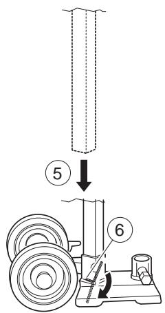
text_image
Diagram showing a mechanical setup with labeled components and directional arrows indicating motion or assembly.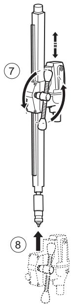
text_image
Technical diagram of a mechanical device with numbered parts and directional arrows indicating motion or assembly.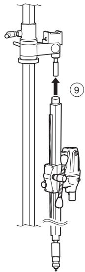
text_image
Technical diagram of a mechanical device with labeled component 9 and directional arrow indicating movement or assembly.
text_image
Technical diagram of a mechanical drilling setup with labeled components and directional arrowtext_image
Technical diagram of a mechanical device with numbered components and labeled parts, including zoomed-in views and assembly instructions.text_image
Technical diagram showing mechanical assembly with numbered components and labeled partsnatural_image
Technical line drawing of a mechanical device with no visible text or symbolstext_image
Technical diagram of a mechanical device with numbered components labeled 1, 2, and 3.natural_image
Technical line drawing of a mechanical device with no visible text or symbolsnatural_image
Line drawing of a cylindrical mechanical component with a central hole and a side pipe (no text or symbols)
natural_image
Line drawing of a mechanical assembly with hands operating a tool (no text or symbols)Acoplamiento deslizante (SMC)
text_image
Technical diagram showing mechanical assembly steps with numbered components and a 15° angle indicatornatural_image
Line drawing of a hand operating a mechanical clamp or fixture (no text or symbols present)natural_image
Line drawing of a car's front camera with attached sensor and cable (no text or symbols)natural_image
Line drawing of a hand holding a small electric motor with visible blades and wiring (no text or symbols)natural_image
Line drawing of two hands operating a mechanical clamp or fixture (no text or symbols present)natural_image
Line drawing of a device with a connector and cable, no text or symbols presenttext_image
Technical diagram of a mechanical testing setup with numbered components and a Husqvarna book cover.natural_image
Line drawing of a pair of trousers with a belt buckle (no text or symbols)natural_image
Technical line drawing of a Husqvarna electric drill press with attached trigger mechanism (no text or symbols)natural_image
Technical line drawings of mechanical components including a bracket, clamps, and a circular housing (no text or symbols)DMS160 AT
natural_image
Line drawing of a hand using a tool to adjust or install a mechanical component (no text or symbols present)DMS160 AT
natural_image
Line drawing of a hand using a handheld tool to adjust or install a mechanical component (no text or symbols present)natural_image
Technical line drawing of a mechanical assembly with no visible text or symbols
natural_image
Technical line drawing of a mechanical assembly with no visible text or symbols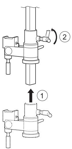
text_image
Technical diagram showing mechanical assembly with labeled parts and directional arrows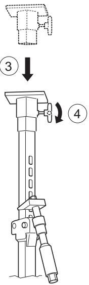
text_image
Technical diagram showing a mechanical device with labeled steps ③ and ④, indicating assembly or operation.
text_image
Diagram showing a mechanical setup with labeled components and directional arrows indicating motion or assembly.
text_image
Technical diagram of a mechanical device with numbered parts and directional arrows indicating motion or assembly.
text_image
Technical diagram of a mechanical device with labeled component 9 and directional arrow indicating movement or assembly.
text_image
Technical diagram of a mechanical drilling setup with labeled components 10 and 11, showing a drill press and base mount.Bohren in Wänden
text_image
Technical diagram showing mechanical assembly with numbered components and a close-up view of a device with labeled parts.text_image
Technical diagram showing mechanical assembly with numbered components and labeled partsnatural_image
Technical line drawing of a mechanical device with no visible text or symbolstext_image
Technical diagram of a mechanical device with numbered parts labeled 1, 2, and 3.natural_image
Technical line drawing of a Huaqvarna electric shaver with no visible text or symbolsBohren in der Decke

natural_image
Line drawing of a cylindrical mechanical component with a flanged end (no text or symbols)
natural_image
Line drawing of a hand using a tool to lift a bottle (no text or symbols)Rutschkupplung (SMC)
text_image
Technical diagram showing mechanical assembly steps with numbered components and a 15° angle indicatornatural_image
Line drawing of a hand using a tool to adjust or install a mechanical component (no text or symbols present)natural_image
Line drawing of a mechanical device with a connector and cable (no text or symbols)natural_image
Line drawing of a hand using a tool to lift a motor (no text or symbols present)natural_image
Line drawing of two hands assembling or adjusting a mechanical component (no text or symbols)natural_image
Line drawing of a medical device with attached connectors (no text or symbols)Vice President, Head of Power Cutters and Construction Equipment
Husqvarna AB
text_image
Technical diagram of a mechanical testing setup with numbered components and a Husqvarna book cover.natural_image
Line drawing of a pair of trousers with a belt buckle (no text or symbols)natural_image
Technical line drawing of a Husqvarna electric drill press with attached trigger and screw head (no text or symbols)natural_image
Technical line drawing of a mechanical testing setup with no visible text or symbolsDMS160 A
natural_image
Diagram of a mechanical device with a magnified inset showing internal components (no text or symbols)DMS160 AT
DMS160 Gyro
DMS160 A/AT
natural_image
Line drawing of a hand using a tool to adjust or install a mechanical component (no text or symbols present)DMS160 AT
natural_image
Line drawing of a hand using a handheld tool to lift a mechanical component (no text or symbols)natural_image
Technical line drawing of a mechanical assembly with no visible text or symbols
natural_image
Technical line drawing of a mechanical assembly with no visible text or symbols
text_image
Technical diagram showing mechanical assembly steps with numbered annotations indicating motion directions
text_image
Technical diagram showing a mechanical device with numbered steps and directional arrows indicating motion or assembly.
text_image
Diagram showing a mechanical setup with labeled components and directional arrows indicating process steps.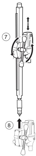
text_image
Technical diagram of a mechanical device with numbered parts and directional arrows indicating motion or assembly.
text_image
Technical diagram of a mechanical device with labeled component 9 and directional arrow indicating movement or assembly.
text_image
Technical diagram of a mechanical device with labeled parts and directional arrow indicating assembly or inspection.Forage dans un mur
text_image
Technical diagram of a mechanical device with numbered components and labeled parts, including zoomed-in views and assembly instructions.text_image
Technical diagram showing mechanical assembly with numbered components and labeled partsnatural_image
Technical line drawing of a mechanical device with no visible text or symbolstext_image
Technical diagram of a mechanical device with numbered parts labeled 1, 2, and 3.natural_image
Technical line drawing of a mechanical device with no visible text or symbolsnatural_image
Line drawing of a cylindrical mechanical component with a flanged end (no text or symbols)
natural_image
Line drawing of a hand using a tool to lift or adjust a mechanical component (no text or symbols present)text_image
Technical diagram showing mechanical assembly steps with numbered components and a 15° angle indicatornatural_image
Line drawing of a hand operating a mechanical device with tools (no text or symbols)natural_image
Line drawing of a device with a connector and cable, no text or symbols presentnatural_image
Line drawing of a hand using a screwdriver to adjust or install an electric motor (no text or symbols present)natural_image
Line drawing of two hands operating a mechanical device (no text or symbols)natural_image
Line drawing of a device with a connector and cable, no text or symbols presenttext_image
Handwritten signature or scribble on a white background, possibly a signature or artistic markHenric Andersson