USER MANUAL LC 48 HUSQVARNA
natural_image
Simple line icon of a forklift inside a circle (no text or symbols)
SE (2-19) DK (20-37)
NO (38-55) FI (56-73)
GB (74-91) FR (92-109)
SYMBOLFÖRKLARING
Symbolförklaring


natural_image
Line drawing of a pair of trousers with a belt buckle (no text or symbols)
natural_image
Line drawing of two boots, one plain and one with laces (no text or symbols)
natural_image
Line drawing of a car's front bumper and rear wheel, showing structural details with arrows indicating points of interest (no text or symbols present)
natural_image
Line drawing of two hands holding a medical instrument (no text or symbols)
natural_image
Diagram of a door handle with hand gesture and circular component (no text or symbols)

natural_image
Mechanical component diagram showing a knob and adjustment knob with an arrow indicating direction (no text or symbols)
natural_image
Line drawing of a person using a lawn mower with three others standing nearby (no text or symbols)
- Starta aldrig maskinen:
natural_image
Line drawing of a car interior showing a hand holding a device, with no visible text or symbols
natural_image
Line drawing of a tire and wheel assembly (no text or symbols)
natural_image
Diagram of a mechanical component with a directional arrow indicating motion (no text or symbols)
natural_image
Mechanical diagram showing gear and shaft assembly with a black arrow indicating a specific component (no text or labels)
natural_image
Technical line drawing showing mechanical components with rotational arrows indicating motion (no text or symbols)
natural_image
Line drawing of a mechanical component with an arrow indicating direction (no text or symbols)
natural_image
Mechanical component diagram showing a rotating shaft and housing with an arrow indicating direction (no text or symbols)
natural_image
Pure mechanical diagram showing a gear or cam mechanism with no text, numbers, or symbols
natural_image
Technical line drawing of a three-part plastic housing assembly (no text or symbols)

natural_image
Technical line drawing of a mechanical device with an inset close-up showing internal components (no text or symbols)

natural_image
Technical line drawing of a mechanical enclosure or housing with internal partitioning (no text or symbols)

natural_image
Technical line drawing of a car interior showing exterior and side views (no text or symbols)
natural_image
Line drawing of two different lawn mower covers, showing hand positioning and mounting details (no text or symbols)
Sidutkast
natural_image
Line drawing of a car engine component with hands adjusting parts (no text or symbols)
Mulchingfunktion
natural_image
Technical line drawing of a mechanical component with an arrow indicating direction (no text or symbols)
natural_image
Line drawing of a car wheel assembly with a handle and seatbelt (no text or symbols)

natural_image
Line drawing of a car's front wheel assembly with hand operating the seat (no text or symbols)
natural_image
Line drawing of a car's seatbelt mechanism with a black arrow indicating the down-left corner (no text or symbols present)
Drivmedel

natural_image
Line drawing of a hand using a tool to adjust or install a component on a vehicle wheel (no text or symbols)
Start och stopp

natural_image
Line drawing of a hand holding a tool with a curved handle and ring (no text or symbols)
natural_image
Line drawing of a person using a manual lawn push tool (no text or symbols)
natural_image
Illustration of two hands using a tool to adjust or install a mechanical component, showing step-by-step assembly (no text or symbols present)
Drivning
natural_image
Line drawing of a hand gripping a cable or wire (no text or symbols)
natural_image
Illustration of hands using a power tool to lift a device, showing motion arrows (no text or symbols)
Stopp
natural_image
Line drawing of two hands holding a medical instrument (no text or symbols)
Tömma gräsuppsamlaren, LC48, LC48V, LC48VE
natural_image
Technical line drawing of a mechanical assembly with no visible text or symbols
natural_image
Illustration of a hand holding a computer monitor with a downward arrow indicating compression (no text or symbols)
UNDERHÅLL
Underhåll


natural_image
Line drawing of a mechanical component with hands and a black arrow indicating a detail (no text or symbols)
natural_image
Technical line drawing of a mechanical component with a highlighted section and arrow (no text or symbols)
natural_image
Hand holding a smartphone with a tool, showing the screen and buttons (no text or symbols visible)
Kniv


natural_image
Mechanical component diagram showing a dial indicator with an arrow pointing to a central hub (no text or symbols present)
natural_image
Mechanical component diagram showing a rotating shaft and housing with a black arrow pointing to a component (no text or symbols)
natural_image
Mechanical component diagram showing a rotating assembly with arrows indicating motion direction (no text or symbols)
- Skruva bort oljepåfyllningslocket.
natural_image
Line drawing of hands using a tool to adjust or install a mechanical component (no text or symbols present)
natural_image
Technical line drawing of a mechanical component with a directional arrow indicating movement (no text or symbols)
- Lossa batterikabelanslutningarna.
natural_image
Diagram of a car interior showing airflow or traffic flow between two vehicle parts (no text or symbols)
natural_image
Technical line drawing of a lawn mower and wheel assembly (no text or symbols)
LC 48V, LC 48VE, LB 48V
natural_image
Line drawing of a car's rear wheel and side panel, showing structural components with arrows indicating movement (no text or symbols)
natural_image
Line drawing of a hand operating a mechanical device with no visible text or symbols
Rengöring klippkåpa
natural_image
Technical line drawing showing two mechanical assembly steps: one with a valve and cable, the other with a coiled tube and connecting tubing (no text or symbols)
natural_image
Diagram of a car interior showing hand positioning and cleaning process (no text or symbols)
natural_image
Illustration of a hand holding a curved object with arrows indicating motion or force (no text or symbols)
natural_image
Mechanical assembly diagram showing a wheel, suspension rod, and mechanical components (no text or labels)
2
natural_image
Mechanical assembly diagram showing a tire and brake system with no visible text or symbols
3

4


natural_image
Line drawing of a pair of trousers with a belt buckle (no text or symbols)
natural_image
Line drawing of a car's front bumper and rear wheel, showing structural details with arrows indicating points of interest (no text or symbols present)
natural_image
Line drawing of two hands holding a medical instrument (no text or symbols)
natural_image
Diagram of a door handle with hand gesture and circular component (no text or symbols)

natural_image
Mechanical component diagram showing a knob and adjustment knob (no text or symbols)
natural_image
Illustration of a person using a lawn mower with three others standing, crossed by a 'X' symbol (no text or labels present)
• Start aldrig maskinen:
natural_image
Line drawing of a car interior showing a hand holding a device with an arrow indicating direction (no text or symbols)
natural_image
Line drawing of a tire and wheel assembly (no text or symbols)
natural_image
Technical line drawing of a mechanical component with a black arrow indicating direction (no text or symbols)
natural_image
Technical line drawing of a mechanical component with no visible text or symbols
natural_image
Technical line drawing showing two mechanical assembly steps with rotational arrows indicating motion (no text or symbols)
natural_image
Line drawing of a mechanical component with an arrow indicating direction (no text or symbols)
natural_image
Mechanical component diagram showing a rotating shaft and housing with an arrow indicating direction (no text or symbols)
natural_image
Pure mechanical diagram showing a gear or cam mechanism with no text, numbers, or symbols
natural_image
Technical line drawing of a three-part plastic housing assembly (no text or symbols)
natural_image
Technical line drawing of a mechanical device with an open lid and internal components, shown in two views (no text or symbols)
natural_image
Technical line drawing of a mechanical enclosure or housing with internal partitioning (no text or symbols)

natural_image
Technical line drawing of a car interior showing exterior and side views (no text or symbols)
natural_image
Line drawing of two different lawn mower covers, showing hand positioning and mounting details (no text or symbols)
Sideudkast
LB48, LB48V, kan anvendes med sideudkast ved at montere sideudkastet på klippekappen.

natural_image
Line drawing of a car engine component with hands adjusting parts (no text or symbols)
Spredningsfunktion
natural_image
Technical line drawing of a car engine component with no visible text or symbols
natural_image
Line drawing of a car interior showing steering wheel, dashboard, and seatbelt (no text or symbols)
natural_image
Technical line drawing of a vehicle chassis frame with hands operating the seat (no text or symbols)
Luk skjoldet og sørg for, at det låses fast med spredningsproppen.
natural_image
Line drawing of a car seatbelt with a black arrow indicating the down-left corner (no text or symbols)
BRÆNDSTOFHÅNDTERING
Drivmiddel

natural_image
Line drawing of a hand using a tool to adjust or install a car engine component (no text or symbols present)
Start og stop

natural_image
Line drawing of a hand holding a tool with a rope and handle (no text or symbols)
natural_image
Line drawing of a person using a manual pushrower to lift a surface (no text or symbols)
natural_image
Line drawing of hands using a tool to adjust or install a mechanical component (no text or symbols present)
natural_image
Line drawing of a hand holding a small object with arrows indicating movement or force (no text or symbols)
Drev
natural_image
Line drawing of a hand gripping a cable or wire (no text or symbols)
Drevet reguleres trinløst.
natural_image
Illustration of hands using a power tool to lift a device, showing motion arrows (no text or symbols)
Stop
Motoren standses ved at slippe motorbremsebøjlen.

natural_image
Line drawing of two hands holding a medical instrument (no text or symbols)
natural_image
Line drawing of a mechanical component with an arrow indicating upward motion (no text or symbols)
natural_image
Illustration of a hand holding a large open book with a downward arrow, no text or symbols present
VEDLIGEHOLDELSE
Vedligeholdelse


natural_image
Line drawing of a hand using a tool to adjust or install a mechanical component (no text or symbols visible)
natural_image
Technical line drawing of a mechanical component with a downward arrow indicating a feature (no text or symbols present)
Rengør filtret ved at slå det imod et plant underlag. Brug aldrig opløsningsmidler med petroleum eller trykluft til at rense filtret.
natural_image
Illustration of a hand holding a smartphone with a tool, showing a curved arrow indicating rotation (no text or symbols present)
Kniv


natural_image
Mechanical component diagram showing a lever mechanism with an arrow indicating direction (no text or symbols)
natural_image
Mechanical component diagram showing a knob and adjustment knob with an arrow indicator (no text or symbols)
natural_image
Mechanical component diagram showing a rotating shaft and housing with directional arrows indicating motion (no text or symbols)
natural_image
Line drawing of a hand turning a car engine component (no text or symbols)
natural_image
Technical line drawing of a mechanical component with a directional arrow indicating movement (no text or symbols)
• Løsn batterikablerne.
natural_image
Diagram of a vehicle engine compartment with hoses and control panel (no text or labels)
natural_image
Technical line drawing of a lawn mower and its side view showing mechanical components (no text or labels)
LC 48V, LC 48VE, LB 48V
natural_image
Line drawing of a car's front bumper and rear wheel, showing structural details with arrows indicating movement (no text or symbols)
natural_image
Line drawing of a mechanical assembly with hands operating a tool (no text or symbols)
natural_image
Technical line drawing showing two mechanical assembly steps: one with a tool inserted into a component, the other with a coiled cable and tubing (no text or symbols present)
natural_image
Diagram of a car interior showing a hand holding a car with a black granular substance inside (no text or symbols)
Indstilling af koblingswire
Koblingswiren indstilles ved at skrue på indstillingsskruen.

natural_image
Illustration of a hand holding a curved object with arrows indicating force or movement (no text or symbols)
natural_image
Mechanical assembly diagram showing a car wheel and suspension components (no text or labels)
natural_image
Mechanical assembly diagram showing a wheel and suspension components (no text or labels)


Hva er hva på gressklipperen? LC 48, LC 48V, LC 48VE
1 Håndtak / styre
2 Drift
3 Starthåndtak
4 Gressoppsamler
5 Brennstofftank
6 Klippehøydehendel
7 Luftfilter
8 Tallerkenfjær
9 Knivbolt
10 Knivfeste
11 Kniv/skjæreutstyr
12 Tennplugg
13 Klippedeksel
14 Lyddemper
15 Vanntilkopling
16 Oljetank
17 Bakre skjerm
18 Motorbremsebøyle
19 Bruksanvisning
20 Mulchingplugg
21 El-start

Hva er hva på gressklipperen? LB 48, LB 48V
1 Håndtak / styre 10 Kniv/skjæreutstyr
2 Koplingsspak 11 Tennplugg
3 Starthåndtak 12 Klippedeksel
4 Brennstofftank 13 Lyddemper
5 Klippehøydehendel 14 Vanntilkopling
6 Luftfilter 15 Oljetank
7 Tallerkenfjær 16 Motorbremsebøyle
8 Knivbolt 17 Bruksanvisning
9 Knivfeste 18 Sideutkast
SIKKERHETSINSTRUKSJONER
natural_image
Line drawing of a pair of trousers with a belt buckle (no text or symbols)
natural_image
Line drawing of two boots, one with a loop handle and the other with a flared front (no text or symbols)
natural_image
Line drawing of a car's front bumper and rear wheel (no text or symbols)
natural_image
Line drawing of two hands holding a curved object, no text or symbols present
- Kontroller at motorbremsen fungerer ordentlig og er uskadd. Plasser gressklipperen på et stabilt, plant underlag og start den. Påse at kniven ikke kan komme i kontakt med bakken eller andre gjenstander.
natural_image
Diagram of a door handle with hand gesture and circular component (no text or symbols)

natural_image
Mechanical component diagram showing a dial indicator and mounting bracket (no text or symbols)
Ved bytte av kniv eller knivfeste skal alltid skive og tallerkenfjær byttes ut.

natural_image
Line drawing of a person using a lawn mower with three others standing nearby (no text or symbols)
(Tanking/Oppbevaring)

- Start aldri maskinen:
1 Hvis du har sølt brennstoff eller motorolje på maskinen. Tørk opp alt søl og la bensinrestene fordampe.
2 Hvis du har sølt brennstoff eller motorolje på deg selv eller klærne dine. Skift klær.
3 Hvis maskijen lekker brennstoff. Kontroller regelmessig med tanke på lekkasje fra tanklokk og brennstoffledninger.
natural_image
Line drawing of a car interior showing a hand holding a device, with no visible text or symbols
natural_image
Line drawing of a tire and wheel assembly (no text or symbols)
natural_image
Technical line drawing of a mechanical component with a black arrow indicating direction (no text or symbols)
natural_image
Technical line drawing of a mechanical component with no visible text or symbols
natural_image
Mechanical diagram showing a gear and wheel assembly with a circular arrow indicating rotational motion (no text or symbols)
natural_image
Mechanical diagram showing a lever mechanism with rotating arrows indicating motion (no text or symbols)
natural_image
Line drawing of a mechanical component with an arrow indicating direction (no text or symbols)
Tøm alltid bensintanken før du legger gressklipperen på siden.
Demontering
- Skru ut bolten som holder kniven.
natural_image
Mechanical component diagram showing a rotating shaft and housing with a black arrow indicating direction (no text or symbols)
natural_image
Diagram of a mechanical component with concentric circles and a central hub, showing no text or symbols.
- Monter skiven og skru bolten ordentlig fast. Bolten skal trekkes til med et moment på 45-60 Nm.
natural_image
Technical line drawing of a three-part plastic housing assembly (no text or symbols)

natural_image
Technical line drawing of a device with open lid and internal compartments, shown in two views (no text or symbols)

natural_image
Technical line drawing of a mechanical enclosure or housing with internal partitioning (no text or symbols)

natural_image
Technical line drawing of a car interior showing exterior and side views (no text or symbols)
natural_image
Line drawing of two different lawn mower levers, showing hand positioning and mounting details (no text or symbols)
Sideutkast
natural_image
Line drawing of a car engine component with hands adjusting parts (no text or symbols)
Mulchingfunksjon
LB48, LB48V, er en gressklipper med mulchingfunksjon.
natural_image
Technical line drawing of a mechanical component with an arrow indicating direction (no text or symbols)
natural_image
Line drawing of a car interior showing hand positioning and seatbelt mechanism (no text or symbols)

natural_image
Line drawing of a vehicle chassis with hands operating the frame (no text or symbols)
natural_image
Line drawing of a car's seatbelt mechanism with a black arrow indicating the down-left corner (no text or symbols present)
BRENNSTOFFHÅNDTERING
Brennstoff

natural_image
Line drawing of a hand using a tool to adjust or install a component on a vehicle (no text or symbols present)
Bruk kun anbefalt motorolje. Se kapitlet Tekniske data.
Start og stopp

natural_image
Line drawing of a hand holding a tool with a curved handle and ring (no text or symbols)
natural_image
Line drawing of a person using a manual lawn push tool (no text or symbols)
natural_image
Illustration showing two hands holding a tool, with arrows indicating movement or force direction (no text or symbols present)
Drift
natural_image
Line drawing of a hand gripping a cable or wire (no text or symbols)
natural_image
Illustration of hands using a power tool to lift a device, showing motion arrows (no text or symbols)
Stopp
natural_image
Line drawing of two hands holding a medical instrument (no text or symbols)
Tømme gressoppsamleren, LC48, LC48V, LC 48VE
natural_image
Technical line drawing of a mechanical assembly with no visible text or symbols
natural_image
Illustration of a hand holding a flatboard with a downward arrow, no text or symbols present
VEDLIKEHOLD
Vedlikehold


natural_image
Line drawing of a mechanical component with hands and a black arrow indicating a detail (no text or symbols)
natural_image
Technical line drawing of a mechanical component with a highlighted section and arrow (no text or symbols)
natural_image
Technical line drawing of a mechanical assembly with no visible text or symbols
natural_image
Hand holding a handheld device with a tool, showing a circular dial and arrow indicating rotation (no text or symbols)
Bruk aldri en maskin som har defekt lyddemper.

Kniv

natural_image
Mechanical component diagram showing a dial indicator and mounting bracket (no text or symbols)
natural_image
Mechanical assembly diagram showing a bolted joint with an arrow indicating direction (no text or symbols)
natural_image
Mechanical component diagram showing a gear assembly with directional arrows indicating motion (no text or labels)
natural_image
Line drawing of a hand using a tool to adjust or install a car engine component (no text or symbols present)
natural_image
Technical line drawing of a mechanical component with circular holes and an arrow indicating direction (no text or symbols)
• Løsne batterikablene.

natural_image
Diagram of a car engine intake system with airflow arrows indicating flow direction (no text or labels)
- Koble til batteriladeren og la batteriet lades i maks. 24 timer.
natural_image
Technical line drawing of a vehicle chassis showing front and side views with arrows indicating components (no text or symbols)
LC 48V, LC 48VE, LB 48V
natural_image
Line drawing of a car's front bumper and rear wheel, showing structural details with arrows indicating points of interest (no text or symbols present)
natural_image
Line drawing of a mechanical assembly with hands operating a tool (no text or symbols)
natural_image
Technical line drawing showing two mechanical assembly steps: one with a tool inserted into a component, the other with a valve and tubing (no text or symbols present)
natural_image
Diagram of a car interior showing a hand inserting granular material into a vehicle (no text or symbols)
natural_image
Illustration of a hand holding a curved object with arrows indicating movement or force (no text or symbols)


Ruohonleikkurin osat? LC 48, LC 48V, LC 48VE
natural_image
Line drawing of a pair of trousers with a belt buckle (no text or symbols)
natural_image
Line drawing of two boots, one with a loop and the other with front laces (no text or symbols)
natural_image
Line drawing of a car's front bumper and rear wheel, showing structural details with arrows indicating points of interest (no text or symbols present)
natural_image
Line drawing of two hands holding a medical instrument (no text or symbols)
natural_image
Diagram of a door handle with hand gesture and circular component (no text or symbols)

natural_image
Mechanical component diagram showing a knob and adjustment knob with an arrow indicator (no text or symbols)
natural_image
Illustration of three men standing beside a lawn mower with crossed-out black X marks (no text or symbols)
natural_image
Line drawing of a car interior showing a hand pressing down the seat with an arrow indicating direction (no text or symbols)
natural_image
Line drawing of a tire and wheel assembly (no text or symbols)
natural_image
Technical line drawing of a mechanical component with a black arrow indicating direction (no text or symbols)
natural_image
Medical illustration showing a shoulder joint with an arrow indicating a specific area (no text or labels present)
natural_image
Technical line drawing showing mechanical components with rotational arrows indicating motion (no text or symbols)
natural_image
Line drawing of a mechanical component with an arrow indicating direction (no text or symbols)
natural_image
Mechanical component diagram showing a rotating shaft and housing with an arrow indicating direction (no text or symbols)
natural_image
Pure mechanical diagram showing a gear or cam mechanism with no text, numbers, or symbols
natural_image
Technical line drawing of a three-part plastic housing assembly with internal compartments and mounting brackets (no text or symbols)

natural_image
Technical line drawing of a mechanical device with an open lid and internal components, shown in two views (no text or symbols)

natural_image
Technical line drawing of a mechanical enclosure or housing with internal partitioning (no text or symbols)

natural_image
Technical line drawing of a vehicle chassis with side and top views (no text or symbols)
natural_image
Line drawing of two different lawn mower covers, showing hand positioning and mounting details (no text or symbols)
Sivuviskuri
natural_image
Line drawing of a car engine component with hands adjusting parts (no text or symbols)
Silppuritoiminto
natural_image
Technical line drawing of a car engine component with no visible text or symbols
natural_image
Line drawing of a car interior showing hand positioning and seatbelt mechanism (no text or symbols)

natural_image
Line drawing of a vehicle chassis with hands operating it (no text or symbols)
natural_image
Line drawing of a car seatbelt with a black arrow indicating a downward adjustment (no text or symbols)
POLTTOAINEEN KÄSITTELY
Polttoaine

natural_image
Line drawing of a hand using a tool to adjust or install a car engine component (no text or symbols present)
KÄYNNISTYS JA PYSÄYTYS
natural_image
Line drawing of a hand holding a tool with a curved handle and ring (no text or symbols)
natural_image
Line drawing of a person using a manual lawn push tool (no text or symbols)
natural_image
Line drawing of hands using a tool to adjust or install a component (no text or symbols present)
natural_image
Line drawing of hands holding a tool with arrows indicating movement (no text or symbols)
Veto
natural_image
Line drawing of a hand gripping a cable or wire (no text or symbols)
natural_image
Illustration of hands using a tool to interact with a device, showing motion arrows (no text or symbols)
Pysäytys
natural_image
Line drawing of two hands holding a medical instrument (no text or symbols)
natural_image
Technical line drawing of a mechanical assembly with no visible text or symbols
natural_image
Illustration of a hand holding a flatboard with a downward arrow, no text or symbols present
KUNNOSSAPITO
Kunnossapito


natural_image
Line drawing of a car wheel assembly with a hand adjusting the component (no text or symbols)
natural_image
Technical line drawing of a mechanical component with a black arrow indicating a feature (no text or symbols present)
natural_image
Hand holding a handheld device with a tool, showing a circular component and a curved arrow indicating rotation (no text or symbols present)
Terä


natural_image
Mechanical component diagram showing a dial indicator and mounting bracket (no text or symbols)
natural_image
Mechanical component diagram showing a rotating shaft and housing with an arrow indicating direction (no text or symbols)
natural_image
Mechanical component diagram showing a rotating shaft and housing with directional arrows indicating motion (no text or symbols)
natural_image
Line drawing of a hand adjusting a mechanical component with a tool (no text or symbols)
natural_image
Technical line drawing of a mechanical component with a directional arrow indicating motion (no text or symbols)
natural_image
Diagram of a car interior showing airflow or traffic flow between two vehicle parts (no text or symbols)
natural_image
Technical line drawing of a lawn mower and wheel assembly (no text or symbols)
LC 48V, LC 48VE, LB 48V
natural_image
Line drawing of a car's front view showing tire, dashboard, and seat components (no text or symbols)
natural_image
Line drawing of a mechanical assembly with hands operating a tool (no text or symbols)
natural_image
Technical line drawing showing two mechanical assembly steps: one with a tool inserted into a component, the other with a coiled tube and tubing (no text or symbols present)
natural_image
Diagram showing a car interior with a hand holding a car component, no text or symbols present
natural_image
Illustration of a hand holding a curved object with arrows indicating force or movement (no text or symbols)
natural_image
Mechanical assembly diagram showing a vehicle's wheel, suspension components, and chassis (no text or labels)
2

natural_image
Mechanical assembly diagram showing a tire and belt drive system (no text or labels)
3
4
WARNING! The machine can be a dangerous tool if used incorrectly or carelessly, which can cause serious or fatal injury to the operator or others.
Please read the operator's manual carefully and make sure you understand the instructions before using the machine.
Never use the machine if persons, especially children or pets, are in the immediate vicinity.
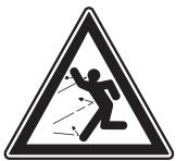
Watch out for thrown objects and ricochets.
Warning: rotating cutter. Keep hands and feet clear.
This product is in accordance with applicable EC directives.
Warning: rotating cutter. Keep hands and feet clear.
Never use the machine indoors or in spaces lacking proper ventilation. Exhaust fumes contain carbon monoxide, an odourless, poisonous and highly dangerous gas.
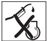
Risk of explosion
Always shut off the engine before refuelling.
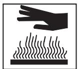
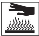
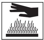
Hot surface
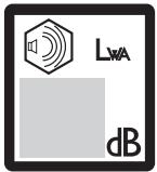
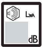
Noise emission to the environment according to the European Community's Directive. The machine's emission is specified in chapter Technical data and on label.


Other symbols/decals on the machine refer to special certification requirements for certain markets.
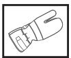
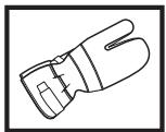
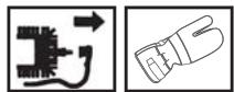
Always wear protective gloves.
Regular cleaning is required.
Visual check.
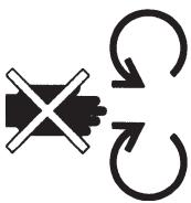
The ignition lead should always be removed from the spark plug before repair, cleaning or maintenance work.
Switch off the engine by releasing the engine brake handle before carrying out any checks or maintenance.


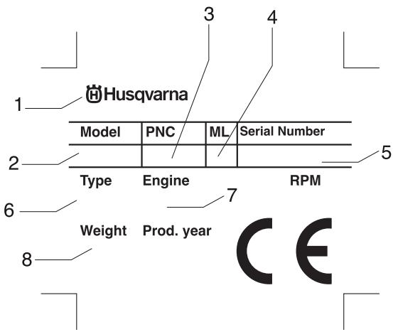
1 Manufacturer
2 Model
3 Product number
4 Maintenance lever
5 Serial number
6 Type
7 Engine information
8 Weight
Steps before using a new lawn mower
- Please read the operator's manual carefully.
- Check that the cutting equipment is correctly fitted and adjusted. See instructions under the heading Assembly.
- Fill with fuel and oil in the engine. See the instructions under the heading fuel handling.

WARNING! Under no circumstances may the design of the machine be modified without the permission of the manufacturer. Always use genuine accessories. Non-authorized modifications and/or accessories can result in serious personal injury or the death of the operator or others.

WARNING! A lawn mower is a dangerous tool if used carelessly or incorrectly and can cause serious, even fatal injuries. It is extremely important that you read and understand the contents of this operator's manual.

WARNING! Long-term inhalation of the engine's exhaust fumes can represent a health hazard.
Husqvarna AB has a policy of continuous product development and therefore reserves the right to modify the design and appearance of products without prior notice.
Contents
KEY TO SYMBOLS
Key to symbols 74
Steps before using a new lawn mower 75
CONTENTS
Contents 76
WHAT IS WHAT?
What is what on the lawn mower? 77
What is what on the lawn mower? 78
SAFETY INSTRUCTIONS
Personal protection 79
Machine's safety equipment 79
General safety precautions 80
General working instructions 81
ASSEMBLY
Fitting the handlebar 83
Dismantling and assembling the cutter 83
FUEL HANDLING
Fuel 85
STARTING AND STOPPING
Starting and stopping 86
MAINTENANCE
Maintenance 87
Air filter 87
Spark plug 87
Muffler 87
Cutter 87
Changing the oil 88
Drive and gearbox 88
Cleaning cutting cover 89
Adjusting the clutch wire 89
Daily maintenance 89
Weekly maintenance 89
Monthly maintenance 89
TECHNICAL DATA
Technical data 90
EC-declaration of conformity 91
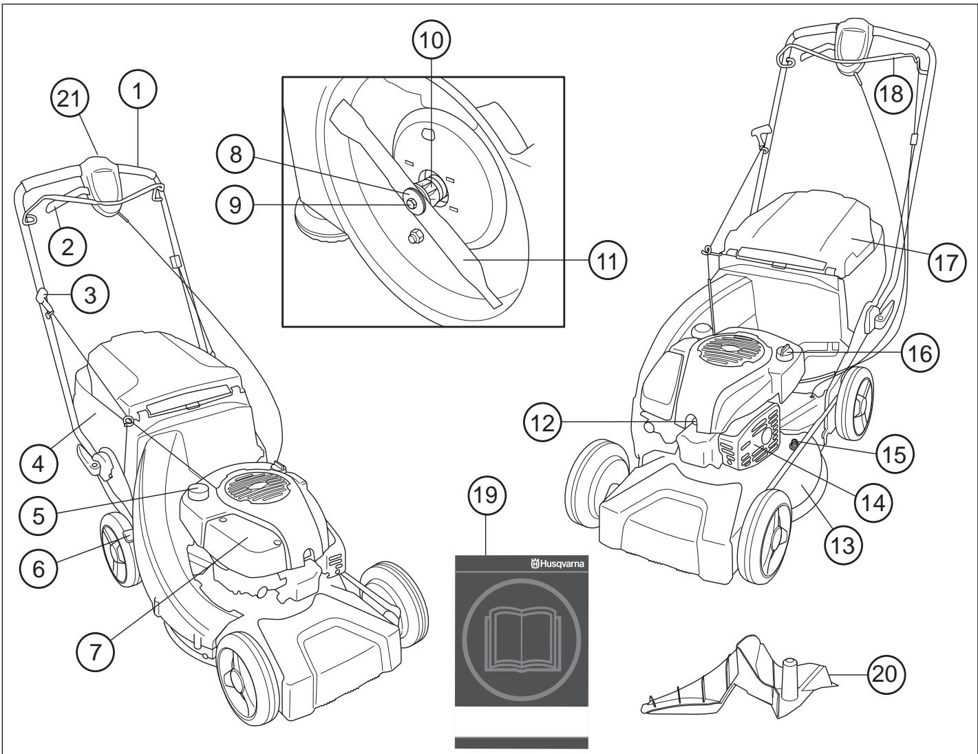
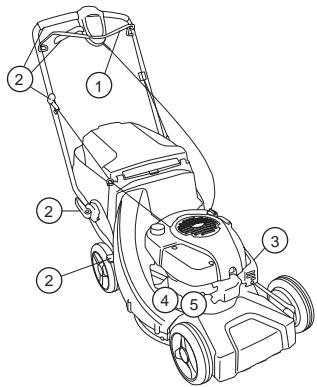
What is what on the lawn mower? LC 48, LC 48V, LC 48VE
1 Handle / handlebar
2 Drive
3 Starter handle
4 Grass catcher
5 Fuel tank
6 Cutting height control
7 Air filter
8 Cup spring
9 Cutter bolt
10 Cutter bracket
11 Cutter/cutting equipment
12 Spark plug
13 Cutting cover
14 Muffler
15 Water connector
16 Oil tank
17 Rear deflector
18 Engine brake handle
19 Operator's manual
20 Mulching plug
21 Electric starter
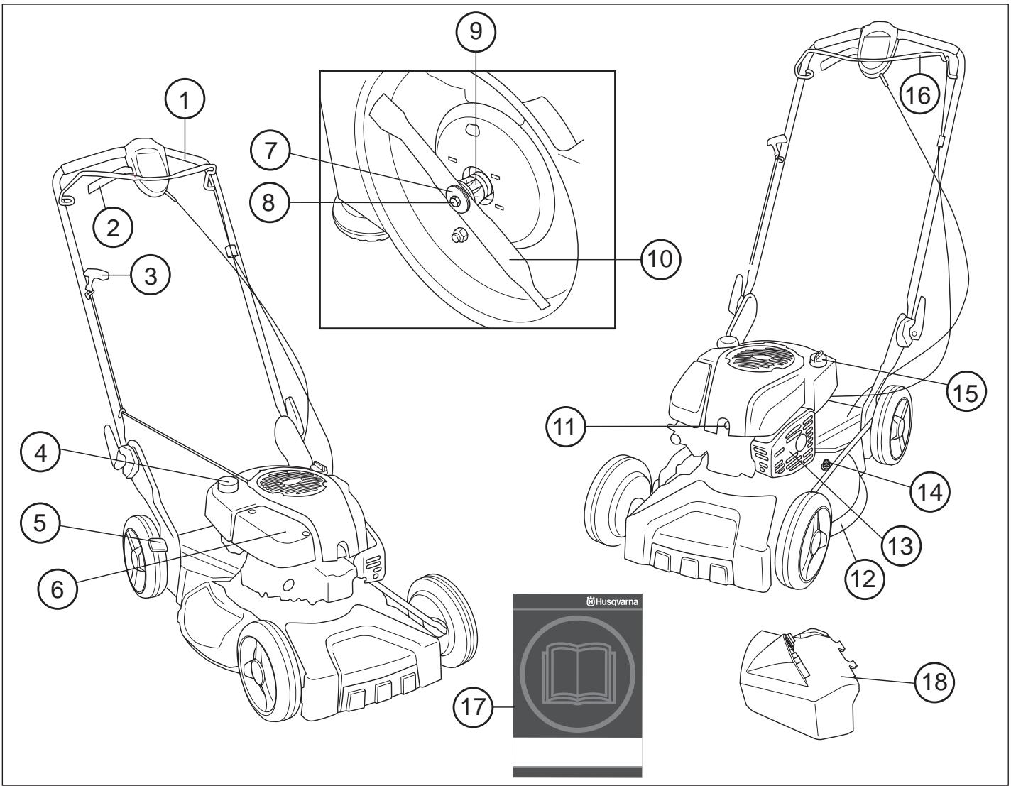
What is what on the lawn mower? LB 48, LB 48V
1 Handle / handlebar
2 Clutch lever
3 Starter handle
4 Fuel tank
5 Cutting height control
6 Air filter
7 Cup spring
8 Cutter bolt
9 Cutter bracket
10 Cutter/cutting equipment
11 Spark plug
12 Cutting cover
13 Muffler
14 Water connector
15 Oil tank
16 Engine brake handle
17 Operator's manual
18 Side ejection
Personal protection

WARNING! You must use personal protection whenever you use the machine.
- Gloves must be worn when required, for example when fitting, inspecting or cleaning cutting attachments.
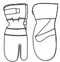
• Always wear heavy, long pants. Do not wear shorts, sandals or go barefoot.

natural_image
Line drawing of a pair of trousers with a belt buckle (no text or symbols)
- Wear sturdy, non-slip boots or shoes.
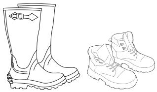
natural_image
Line drawing of two boots, one with a loop handle and the other with a flared front (no text or symbols)
Generally clothes should be close-fitting without restricting your freedom of movement.
Machine's safety equipment
This section describes the machine's safety equipment, its purpose, and how checks and maintenance should be carried out to ensure that it operates correctly. See the "What is what?" section to locate where this equipment is positioned on your machine.

WARNING! Never use a machine that has faulty safety equipment! Carry out the inspection, maintenance and service routines listed in this section.
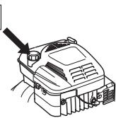
Cutting cover and protective cover
The protective cover is designed to reduce the risk of crush injuries and to catch a broken drive belt. Check that the protective cover is undamaged and that it is properly secured.
natural_image
Line drawing of a vehicle's rear wheel and side panel with arrows indicating motion or force directions (no text or symbols)
The cutting cover is designed to reduce vibration and to reduce the risk of cuts. Make sure the cutting cover is not damaged and that there are no visible defects such as cracks.
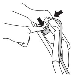
Engine brake handle
The engine brake is designed to stop the engine. When the grip on the engine brake handle is released the engine should stop.

natural_image
Line drawing of two hands holding a medical instrument (no text or symbols)
- Check that the engine brake works correctly and is undamaged.
Place the lawn mower on firm, flat surface and start it. Make sure that the cutter cannot come into contact with the ground or other objects.
Apply full throttle and then release the brake handle. The engine brake should always be adjusted so that the engine stops within 3 seconds.
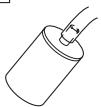
Muffler
The muffler is designed to keep noise levels to a minimum and to direct exhaust fumes away from the user.
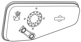
natural_image
Diagram of a door handle with hand gesture and circular component (no text or symbols)

WARNING! The exhaust fumes from the engine are hot and may contain sparks which can start a fire. Never start the machine indoors or near combustible material!
In areas with a hot, dry climate there is a high risk of fires. These areas are sometimes controlled by legislation and requirements that among other things the muffler must be equipped with an approved type of spark arrestor mesh.
For mufflers it is very important that you follow the instructions on checking, maintaining and servicing your machine.

WARNING! The muffler gets very hot in use and remains so for a short time afterwards. Do not touch the muffler if it is hot!
- Never use a machine that has a faulty muffler.
- Check that the muffler is securely attached and not damaged.
SAFETY INSTRUCTIONS
Cutting equipment
Make sure the cutter does not hit foreign objects such as stones, roots or the like. This can make the cutter dull and bend the engine shaft. Always ensure the cutter is well ground and balanced correctly. See also instructions under the heading Maintenance.
Check the cutting attachment. Never use blunt, cracked or damaged equipment.
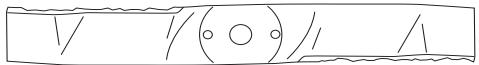
Also check that the cutter bolt is undamaged and that the engine shaft is not bent.

natural_image
Mechanical component diagram showing a bolt and nut assembly (no text or symbols)
The washer and cup spring should always be replaced when changing the cutter or cutter bracket.

WARNING! Never use a machine with faulty safety equipment. The machine's safety equipment must be checked and maintained as described in this section. If your machine fails any of these checks contact your service agent to get it repaired.
General safety precautions
- A lawn mower is only designed to mow lawns. The only accessories you can use with this engine unit are the cutters we recommend in the Technical data chapter.
- Never use the machine if you are tired, if you have drunk alcohol, or if you are taking medication that could affect your vision, your judgement or your co-ordination.
- Keep in mind that the operator is responsible for accidents or hazards occurring to other people or their property.

WARNING! Running an engine in a confined or badly ventilated area can result in death due to asphyxiation or carbon monoxide poisoning.
- You must use personal protection whenever you use the machine. See the instructions under the heading Personal protection.
- Never use a machine that has been modified in any way from its original specification.
- Never use any accessories other than those recommended in this manual. See instructions under the headings Cutting equipment and Technical data.

WARNING! A faulty cutting attachment may increase the risk of accidents.
- Never use a machine that is faulty. Carry out the checks, maintenance and service instructions described in this manual. Some maintenance and service measures must be carried out by trained and qualified specialists. See instructions under the heading Maintenance. Before use:
1 Check that the engine brake works correctly and is undamaged. See the instructions under the heading Checking the braking effect.
2 Check that all handles and controls are undamaged and free of oil.
3 Check that the muffler is securely attached and not damaged.
4 Check that all parts of the lawn mower are tightened correctly and that they are not damaged or missing.
5 Check that the cutter is undamaged and not cracked. Replace the cutter if necessary.
Starting

WARNING! Long-term inhalation of the engine's exhaust fumes can represent a health hazard.
- Never start a lawn mower unless the cutters and all covers are fitted correctly.
- Never start the machine indoors. Exhaust fumes can be dangerous if inhaled.
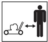
- Ensure that the working area is sufficiently illuminated to create a safe working environment.
- Observe your surroundings and make sure that there is no risk of people or animals coming into contact with the cutting equipment. The operator is responsible for any unsafe situations or risks that people and property are exposed to.
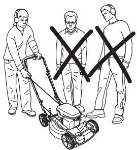
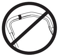
natural_image
Illustration of a person using a lawn mower to stand with three others crossed out (no text or symbols)
- Place the lawn mower on firm, flat surface and start it. Make sure that the cutter cannot come into contact with the ground or other objects.
• Never twist the starter cord around your hand.
See the instructions under the heading Start and stop.
Fuel safety
(Refuelling/Storage.)

WARNING! Fuel and fuel vapour are highly inflammable. Take care when handling fuel and engine oil. Bear in mind the risk of fire, explosion and inhaling fumes.
- Never refuel the machine while the engine is running.
- Always ensure there is adequate ventilation when refuelling and filling oil.
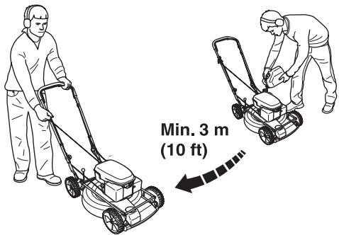
- Move the machine at least 3 m from the refuelling point before starting it.

• Never start the machine:
1 If you have spilt fuel or engine oil on the machine. Wipe off the spill and allow the remaining fuel to evaporate.
2 If you spill fuel or engine oil on yourself or your clothes. Change your clothes.
3 If the machine is leaking fuel. Check regularly for leaks from the fuel cap and fuel lines.
Transport and storage
- The fuel and engine oil tanks should be emptied before longer periods of storage or when transporting the lawn mower. Ask where you can dispose of surplus fuel and engine oil at your local petrol station.
- Always store the lawn mower and fuel so that any leakage or vapours do not risk coming into contact with sparks or naked flames. For example, electrical machines, electric motors, relays/switches, boilers, or the like.
- Always store fuel in an approved container designed for that purpose.
General working instructions

WARNING! This section describes basic safety precautions for working with the lawn mower. This information is never a substitute for professional skills and experience. If you get into a situation where you feel unsure about how to progress, stop and seek expert advice. Contact your dealer, service agent or an experienced lawn mower user. Avoid all usage which you consider to be beyond your capability
Basic safety rules
- Look around you:
- To ensure that people, animals or other things cannot affect your control of the machine.
- To make sure that none of the above might come into contact with the cutting equipment.
- Branches, twigs, stones, etc. should be removed from the lawn before you start to mow. Make sure the cutter does not hit foreign objects such as stones, roots or the like. This can make the cutter dull and bend the engine shaft.
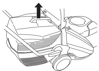
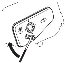
- Never lift up the lawn mower or carry it around when the engine is running. If you must lift the lawn mower, first switch off the engine and disconnect the ignition lead from the spark plug.
natural_image
Line drawing of a mechanical component with an arrow indicating direction (no text or symbols)
- Do not use the machine in bad weather, such as dense fog, heavy rain, strong wind, intense cold, etc. Working in bad weather is tiring and often brings added risks, such as icy ground.
- Make sure you can move and stand safely. Check the area around you for possible obstacles (roots, rocks, branches, ditches, etc.) in case you have to move suddenly. Take great care when working on sloping ground.
- The lawn mower should not be used on inclines greater than 30 degrees.
- The engine should be switched off when moving over ground that is not to be mowed. For example, gravel paths, stone, shingle, asphalt, etc.

The brake handle must never be permanently anchored in handle when the machine is running.
Follow the instructions above, but do not use a lawn mower in a situation where you cannot call for help in case of an accident.
Basic mowing technique

WARNING! Make sure that your hands and feet do not come near the cutting attachment when the engine is running.
General
- Mowing slopes can be dangerous. Do not use the lawn mower on very steep slopes.
- The lawn mower should not be used on inclines greater than 30 degrees.
- On sloping ground you should work along the slope. It is much easier to work along a slope than it is to work up and down it.
- Branches, twigs, stones, etc. should be removed from the lawn before you start to mow.
- Never lift up the lawn mower or carry it around when the engine is running. If you must lift the lawn mower, first switch off the engine and disconnect the ignition lead from the spark plug.
- Make sure the cutter does not hit foreign objects such as stones, roots or the like. This can make the cutter dull and bend the engine shaft. A bent axle gives imbalance and heavy vibration, which results in a great risk of the cutter becoming loose.
- If any foreign object is hit or if vibrations occur stop the machine immediately. Disconnect the HT lead from the spark plug. Check that the machine is not damaged. Repair any damage.
- Never mow more than 1/3 of the length of the grass. This especially applies during dry periods. Mow first with the cutting height set high. Then check the result and lower to an appropriate height. If the grass is really long, drive slowly and mow twice if necessary.

- Never run with the machine when it is running. You should always walk with the lawn mower.
Pay particular attention when pulling the machine towards you during work.
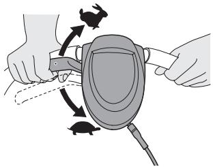
Cutting height
Shut down the engine before changing the cutting height.
The cutting height can be adjusted in five different steps, mm.

natural_image
Line drawing of a tire and wheel assembly (no text or symbols)
Do not set the cutting height too low as there is a risk that the cutters might hit slopes with unevenness.
Adjusting the cutting height
Shut down the engine before changing the cutting height.
Set the cutting height using the cutting height control on the right-hand side of the lawn mower.
- To lower the cutting height move the lever to the right and then forward.

natural_image
Technical line drawing of a mechanical component with a black arrow indicating direction (no text or symbols)
- To raise the cutting height move the lever to the right and then backward.
natural_image
Technical line drawing of a mechanical component with no visible text or symbols
Do not set the cutting height too low as there is a risk that the cutters might hit slopes with unevenness.
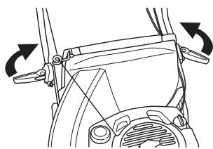
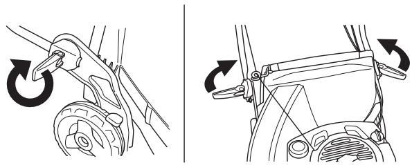
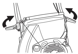
Fitting the handlebar
Take care not to damage the cables and wires when you fold up the handlebar.
Lift up the handlebar until the handlebar's upper tubular construction comes directly opposite to the handlebar's lower section. Tighten the knob correctly.
natural_image
Technical illustration showing two mechanical components with rotational arrows indicating motion (no text or symbols)
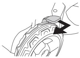
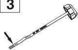
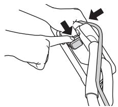
Dismantling and assembling the cutter


WARNING! Always wear heavy-duty gloves when servicing and maintaining the cutting equipment. The cutters are very sharp and cuts can occur very easily.
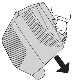
The ignition lead should always be removed from the spark plug before repair, cleaning or maintenance work.
natural_image
Line drawing of a mechanical component with an arrow indicating direction (no text or symbols)
Always empty the fuel tank before you place the lawn mower on its side.
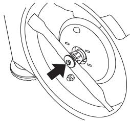
Dismantling
• Unscrew the bolt holding the cutter.

natural_image
Mechanical component diagram showing a rotating shaft and housing with an arrow indicating direction (no text or symbols)
- Remove bolt, washer and cup spring.
- Remove the cutter.
Assembly
- Position the cutter so that the cutting edge faces in the direction of rotation.
- Fit the cup spring, make sure it centres correctly on the engine shaft.
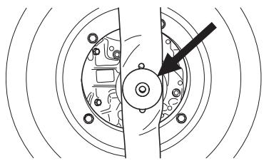
natural_image
Pure mechanical diagram showing a gear or cam mechanism with no text, numbers, or symbols
- Fit the washer and tighten the bolt correctly. The bolt should be tightened with a torque of 45-60 Nm.
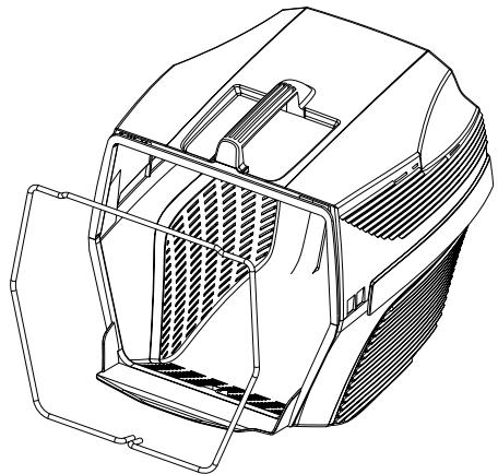
Assembly of the catcher

natural_image
Technical line drawing of a three-part plastic housing assembly with internal compartments and mounting brackets (no text or symbols)
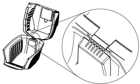
natural_image
Technical line drawing of a device with an open lid and internal components, shown in two views (no text or symbols)

natural_image
Technical line drawing of a mechanical enclosure or housing with internal compartments and mounting brackets (no text or symbols)

natural_image
Technical line drawing of a vehicle chassis with side and top views (no text or symbols)
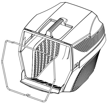
- Lift the hind shield and suspend the grass container.
natural_image
Line drawing of two different lawn mower levers, showing hand positioning and mounting details (no text or symbols)
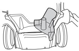
Side ejection
LB48, LB48V, can be used with side ejection by fitting the side ejector on the cutting cover.

Lift up the side cover and place the side ejector on the shaft.

natural_image
Line drawing of a car engine component with hands adjusting parts (no text or symbols)
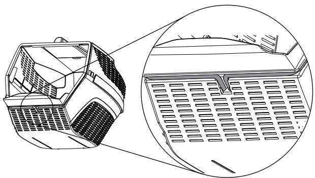
Mulching function
LB48, LB48V, is a lawn mower with mulching function.
LC48, LC48V, LC 48VE, can be used with mulching function in the following way:
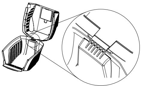
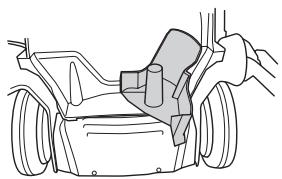
Lift up the back shield and remove the container.

natural_image
Technical line drawing of a car engine component with no visible text or symbols
Insert the mulching plug into the collector channel.

natural_image
Line drawing of a car interior showing hand positioning and seatbelt mechanism (no text or symbols)
natural_image
Line drawing of a car's front wheel assembly with hand operating the seat (no text or symbols)
Close the shield and ensure that it is locked with the mulching plug.
natural_image
Line drawing of a car seatbelt buckle with a black arrow indicating the down-left corner (no text or symbols)
Fuel

WARNING! Always ensure there is adequate ventilation when handling fuel.
Petrol
- Use good quality unleaded petrol. Leaded petrol can be used if unleaded petrol is not available.
• Fuel should be at least 77 octane.
- If the machine is not used for some time the fuel tank should be emptied and cleaned.
Engine oil
Check the oil level before starting the lawn mower. A too low oil level can cause serious damage to the engine.
- For the best result and function use HUSQVARNA four-stroke oil.
- If HUSQVARNA four-stroke oil is not available, you may use another four-stroke oil of good quality. Contact your dealer when selecting oil. In general SAE 30 is recommended.
• Never use oil intended for two-stroke engines.
Check the oil level before starting the lawn mower. A too low oil level can cause serious damage to the engine.
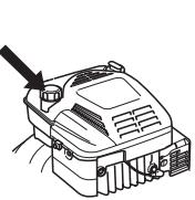
Oil level
Unscrew the oil filler cap and check the oil level on the dipstick fitted to the cover.

natural_image
Line drawing of a hand using a tool to adjust or install a component on a vehicle (no text or symbols present)
The oil filler cap must be completely screwed down to give a correct picture of the oil level.
If the oil level is low, fill using engine oil up to the upper level on the dipstick.
Only use recommended engine oil. See the Technical data section.
Fuelling

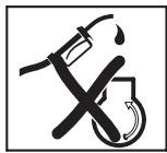
WARNING! Taking the following precautions, will lessen the risk of fire:
Do not smoke or place hot objects near fuel.
Always shut off the engine before refuelling.
When refuelling, open the fuel cap slowly so that any excess pressure is released gently.
Tighten the fuel cap carefully after refuelling.
Always move the machine away from the refuelling area before starting.
Do not fill too much petrol. Leave about 35 mm under the filler cap so that the fuel can expand.
Clean around the fuel cap. Clean the fuel and oil tank regularly. The fuel filter should be changed at least once a year. Contamination in the tanks causes malfunction.
Always move the machine about 3 metres from the refuelling position before starting.
STARTING AND STOPPING
Starting and stopping

WARNING! Note the following before starting:
Do not start a lawn mower unless the cutter and all covers are fitted correctly. Otherwise the cutter could come loose and cause personal injuries.
Always move the machine away from the refuelling area before starting.
Place the machine on a flat surface. Ensure the cutting attachment cannot come into contact with any object.
Keep people and animals well away from the working area.
Starting
Ensure the ignition lead sits correctly on the spark plug.
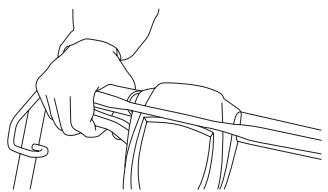
Pull the engine brake handle against the upper handlebar with your left hand.

natural_image
Line drawing of a hand holding a tool with a rope and handle (no text or symbols)
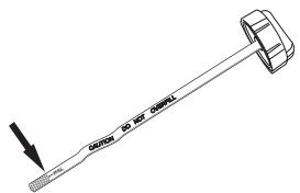
Grip the starter handle, slowly pull out the cord with your right hand until you feel some resistance (the starter pawls grip), now quickly and powerfully pull the cord. Never twist the starter cord around your hand.

natural_image
Line drawing of a person using a manual lawn tool to lift a cart (no text or symbols)
CAUTION! Do not pull the starter cord all the way out and do not let go of the starter handle when the cord is fully extended. This can damage the machine.
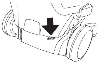
LC 48VE are equipped with electronic start which is used in the following way.
- Before using the electronic start for the first time you need to charge the battery. See instructions under the heading Maintenance.
- Fold in the engine brake handle towards the handlebar.
- Insert the ignition key and push the key.

natural_image
Illustration of two hand positions on a tool, showing mechanical assembly and adjustment (no text or symbols)
Drive
The machines are self-propelling with backwheel drive. To use the drive on the wheel pull the clutch lever towards you.
natural_image
Line drawing of a hand gripping a cable or wire (no text or symbols)
The drive can be gradually controlled.

natural_image
Illustration of hands using a power tool to lift a device, showing motion arrows (no text or symbols)
Stopping
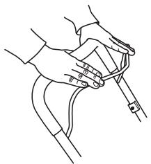
Stop the engine by releasing the engine brake handle.
natural_image
Line drawing of two hands holding a medical instrument (no text or symbols)
Emptying the grass collector, LC48, LC48VE, LC48V
- Lift up the back shield and remove the container.
natural_image
Technical line drawing of a mechanical assembly with no visible text or symbols
- Turn the container upside down to empty it of all the grass.
natural_image
Illustration of a hand holding a computer monitor with a downward arrow indicating compression (no text or symbols)
MAINTENANCE
Maintenance


WARNING! Make sure the cutting attachment has stopped before cleaning, carrying out repairs or an inspection. Disconnect the HT lead from the spark plug.
The ignition lead should always be removed from the spark plug before repair, cleaning or maintenance work.
Air filter
The air filter must be regularly cleaned to remove dust and dirt in order to avoid:
• Carburettor malfunctions
- Starting problems
- Loss of engine power
• Unnecessary wear to engine parts.
• Excessive fuel consumption.
An air filter that has been in use for a long time cannot be cleaned completely. The filter must therefore be replaced with a new one at regular intervals. A damaged air filter must always be replaced.
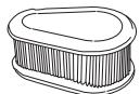
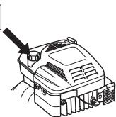
Cleaning the air filter
Remove the air filter cover.

natural_image
Line drawing of a mechanical component with hands and a black arrow indicating a detail (no text or symbols)
Remove the air filter and check that it is undamaged. Replace with a new air filter if you believe it to be defective.

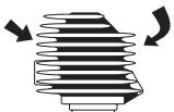
natural_image
Technical line drawing of a mechanical component with a downward arrow indicating a feature (no text or symbols present)
Clean the filter by knocking the filter against a flat surface. Never use solvent with petroleum, for example, kerosene, or compressed air to clean the filter.
When reassembling, make sure that the filter completely seals against the filter holder.
Spark plug

WARNING! The muffler gets very hot in use and remains so for a short time afterwards. Do not touch the muffler if it is hot!
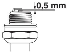
If the machine is low on power, difficult to start or runs poorly at idle speed: always check the spark plug first before taking any further action. If the spark plug is dirty, clean it and check
that the electrode gap is 0.5 mm. The spark plug should be replaced after about a month in operation or earlier if necessary.
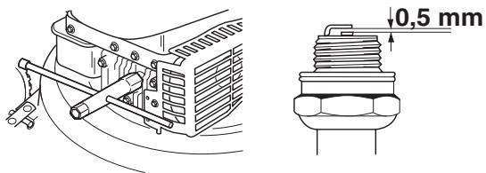
CAUTION! Always use the recommended spark plug type! Use of the wrong spark plug can damage the piston/cylinder.
Muffler
The muffler is designed to reduce the noise level and to direct the exhaust gases away from the operator. The exhaust gases are hot and can contain sparks, which may cause fire if directed against dry and combustible material.
Regularly check that the muffler is securely attached to the machine.
natural_image
Hand holding a handheld device with a tool, showing a circular component and a curved arrow indicating rotation (no text or symbols present)
Never use a machine that has a faulty muffler.

Cutter

WARNING! Always wear heavy-duty gloves when repairing the cutting attachment. The blades are very sharp and can easily cause cuts.
It is important to have a sharp and correctly balanced cutter. Loosen the bolt holding the cutter and leave the cutter at a service workshop at least once a year for grinding and balancing. An appropriate time to do this is after the mowing season has finished.

natural_image
Mechanical component diagram showing a dial indicator and mounting bracket (no text or symbols)
If the cutter or cutter bracket need to be changed you must replace the cutter bolt, washer and cup spring at the same time.
The bolt should be tightened with a torque of 45-60 Nm when you fit the cutter again. See instructions under the heading Assembly.
If the cutter hits foreign objects such as stones, roots or the like the cutter will slip against the cutter bracket. This may mean that the contact surface of the cutter bracket appears slightly worn, which is completely normal. This is a safety device, which reduces the risk of the engine shaft becoming bent.
Changing the oil
The engine oil should be changed each year and every 25 working hours.
When changing the oil proceed as follows::
- Empty the fuel tank by running the machine until the tank is empty.
- Disconnect the HT lead from the spark plug.
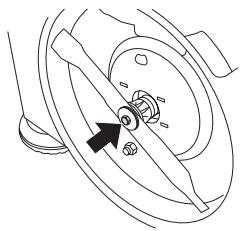
• Unscrew the bolt holding the cutter.
natural_image
Mechanical component diagram showing a rotating shaft and housing with an arrow indicating direction (no text or symbols)
- Loosen the bolts holding the protective hood and then lift off the hood.

natural_image
Mechanical component diagram showing a rotating shaft and housing with directional arrows indicating motion (no text or symbols)
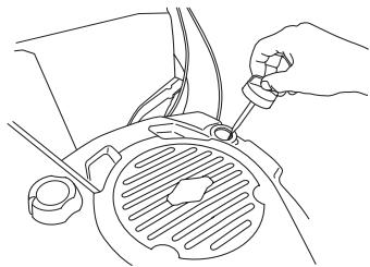
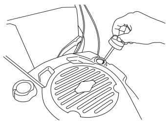
• Unscrew the oil filler cap.
natural_image
Line drawing of a hand using a tool to adjust or install a component on a vehicle (no text or symbols present)
- The oil can be drained from the underside by loosening the oil plug. Do not forget to refit the oil plug before filling with oil again.
Ask where you can dispose of surplus engine oil at your local petrol station.
- Fill with new engine oil of a good quality. See the Technical data section.
- Check the oil level with the dipstick on the oil filler cap.
- The oil filler cap must be completely screwed down to give a correct picture of the oil level. If the oil level is low, fill using engine oil up to the upper level on the dipstick.
- Screw on the oil filler cap.
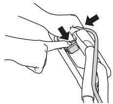
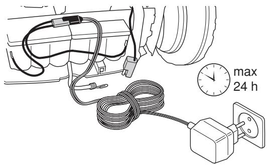
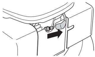
Charge the battery
The battery can be charged as follows:
- Push the locking open and remove the battery cover.
natural_image
Technical diagram of a mechanical component with a directional arrow indicating movement (no text or symbols present)
- Loosen the battery cable connections.
natural_image
Diagram of a car engine compartment showing airflow path and valve placement (no text or labels)
- Connect the battery charger and charge the battery for max. 24 hours.

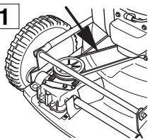
Drive and gearbox

LC 48V, LC 48VE
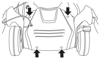
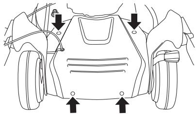
- Lift up the back shield and remove the container.
- Remove the collector cover's 4 screws and lift off the cover.
natural_image
Technical line drawing of a lawn mower and wheel assembly (no text or symbols)
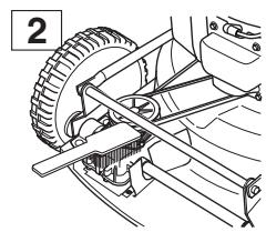
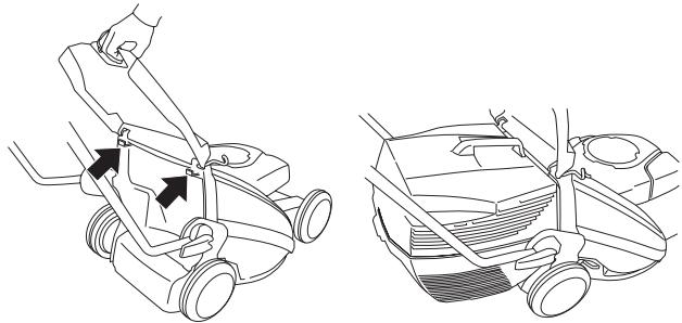
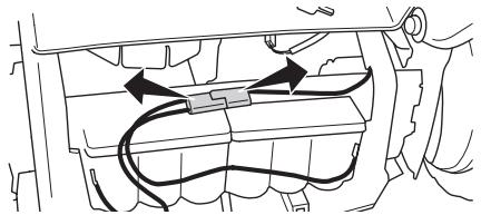
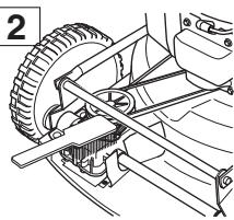
LC 48V, LB 48V, LC 48VE
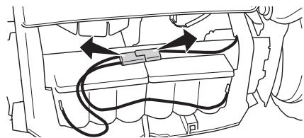
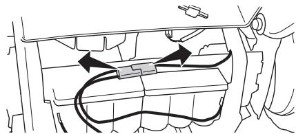
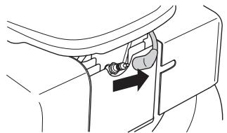
- Ensure the wheels and wheel axles are clean and free from leaves, grass, etc. It is also important to keep clean around the drive gearbox.
- Remove the protective cover by unscrewing the screws.
natural_image
Line drawing of a car's front bumper and rear wheel, showing structural details with arrows indicating points of interest (no text or symbols present)
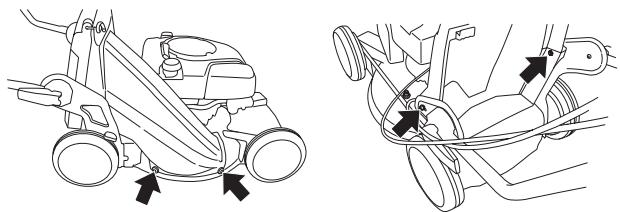
• Now guide the protective cover out and upwards.
- Clean the gearbox with a brush. Also check that the drive belt and belt pulley are undamaged, for example, no cracks.

natural_image
Line drawing of a mechanical assembly with hands operating a tool (no text or symbols)
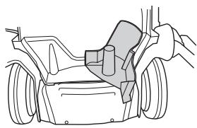
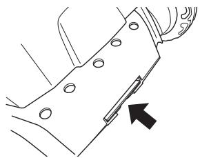
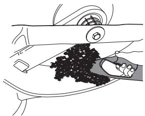
Cleaning cutting cover
- Connect a water hose to the cutting cover connection.

natural_image
Technical line drawing showing two mechanical assembly steps: one with a tool inserted into a component, the other with a valve and tubing (no text or symbols present)
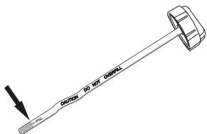
Scrape off the remainder with the scrape supplied with the machine.
natural_image
Diagram of a car interior showing hand cleaning the dashboard and wheel (no text or symbols)
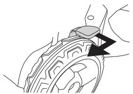
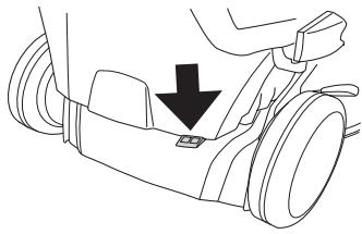
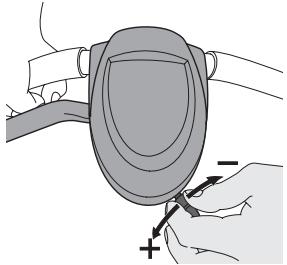
Adjusting the clutch wire
The clutch wire is adjusted by turning the adjustment screw.
natural_image
Illustration of a hand holding a curved object with a plus sign, no text or symbols present
Below you will find some general maintenance instructions.
Daily maintenance
1

2
3
4

5

6

1 Check that the engine brake handle works safely.
2 Brush leaves, grass and the like off of the lawn mower.
3 Check the oil level.
4 Clean the air intake on the starter. Check the starter and starter cord.
5 Check that nuts and screws are tight.
6 Check the cutting attachment. Never use blades that are dull, cracked or damaged.
Weekly maintenance
1
2

3
1 Clean the air filter. Replace if necessary.
2 Clean the spark plug. Check that the electrode gap is 0.51 mm.
3 Clean the cooling fins on the cylinder.
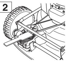
Monthly maintenance
1
natural_image
Mechanical assembly diagram showing a car wheel and suspension components (no text or labels)
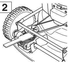
2
natural_image
Mechanical assembly diagram showing a tire and belt drive system (no text or labels)
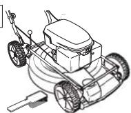
3
4
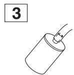
1 Check that drive belt is not damaged and is not visibly defective.
2 Clean the gearbox.
3 Check the fuel filter and the fuel hose. Replace if necessary.
4 Clean the inside of the fuel tank.
TECHNICAL DATA
Technical data
| LC 48 | LC 48V | LB 48 | LB 48V | LC 48VE |
| Engine | Briggs & Stratton | Briggs & Stratton | Briggs & Stratton | Briggs & Stratton | Briggs & Stratton |
| Cylinder displacement, cm3 | 190 | 190 | 190 | 190 | 190 |
| Speed, rpm | 2900 | 2900 | 2900 | 2900 | 2900 |
| Ignition system |
| Spark plug | ChampionRJ19LM | ChampionRJ19LM | ChampionRJ19LM | ChampionRJ19LM | ChampionRJ19LM |
| Electrode gap, mm | 0,5 | 0,5 | 0,5 | 0,5 | 0,5 |
| Fuel and lubrication system |
| Fuel tank capacity, litre | 1,2 | 1,2 | 1,2 | 1,2 | 1,2 |
| Oil tank capacity, litre | 0,6 | 0,6 | 0,6 | 0,6 | 0,6 |
| Engine oil | SAE 30 | SAE 30 | SAE 30 | SAE 30 | SAE 30 |
| Weight |
| Lawn mower with empty tanks, kg | 38 | 38 | 34 | 34 | 43 |
| Sound power level(see note 2) |
| Noise pressure level at the operators ear, dB(A) | 81 | 81 | 79 | 79 | 81 |
| Noise emissions(see note 1) |
| Sound power level, measured dB(A) | 95 | 95 | 93 | 93 | 95 |
| Sound power level, guaranteed LwA dB(A) | 96 | 96 | 95 | 95 | 96 |
| Vibration levels(see note 2) |
| Handle left, m/s2 | 6,0 | 6,0 | 2,7 | 2,7 | 6,0 |
| Handle right, m/s2 | 5,0 | 5,0 | 4,7 | 4,7 | 5,0 |
| Cutting |
| Cutting system | 3 in 1 | 3 in 1 | 2 in 1 | 2 in 1 | 3 in 1 |
| The cutting height can be adjusted in five different steps, mm. | 25-70 | 25-70 | 25-70 | 25-70 | 25-70 |
| Cutting width, mm | 480 | 480 | 480 | 480 | 480 |
| Cutter | Fixed | Fixed | Fixed | Fixed | Fixed |
| Drive |
| Speed, km/h | - | 5,4 | - | 5,4 | 5,4 |
Note 1: Noise emissions in the environment measured as sound power ( LWA ) in conformity with EC directive 2000/14/EC.
Rem. 2: Vibrations and sound pressure measured according to EN 836:1997/A2:2001
(Applies to Europe only)
Husqvarna AB, SE-561 82 Huskvarna, Sverige, tel: +46-36-146500, declares under sole responsibility that the lawn mowers Husqvarna LC 48, LC 48V, LC 48VE, LB 48 and LB48 V from the serial numbers 081500001 and onwards comply with the requirements of the COUNCIL'S DIRECTIVE:
- of June 22, 1998 "relating to machinery" 98/37/EC.
- of December 15, 2004 "relating to electromagnetic compatibility" 2004/108/EC.
- of May 8, 2000 "relating to the noise emissions in the environment" 2000/14/EC.
For information relating to noise emissions, see the chapter Technical data.
Registered body 0404, SMP Svensk Maskinprovning AB, Fyrisborgsgatan 3, SE-754 50 Uppsala, Sweden, has issued reports regarding the assessment of conformity according to annex VI of the COUNCIL'S DIRECTIVE of May 8, 2000 "relating to the noise emissions in the environment" 2000/14/EC.
The certificates have the numbers:
01/901/071 - Husqvarna LC 48, LC 48V
01/901/072 - Husqvarna LB 48, LB 48V
01/901/084 - Husqvarna LC 48VE
Huskvarna 13 October 2008

Bengt Ahlund, Development manager
EXPLICATION DES SYMBOLES
Attention: projections et ricochets.


natural_image
Line drawing of a pair of trousers with a belt buckle (no text or symbols)
natural_image
Line drawing of two boots, one plain and one with visible sole details (no text or symbols)
natural_image
Line drawing of a car's front view showing tire, dashboard, and seat components with arrows indicating motion direction (no text or symbols)
natural_image
Line drawing of two hands holding a medical instrument (no text or symbols)
natural_image
Simple line drawing of a door handle with hand gesture and circular object (no text or symbols)

natural_image
Mechanical component diagram showing a knob and adjustment knob with an arrow indicator (no text or symbols)
natural_image
Illustration of a lawn mower with three people standing and crossed out by a large 'X' symbol (no text or labels present)
natural_image
Line drawing of a mechanical component with an arrow indicating direction (no text or symbols)
natural_image
Line drawing of a tire and wheel assembly (no text or symbols)
natural_image
Diagram of a mechanical component with a black arrow indicating direction (no text or symbols present)
natural_image
Diagram of a mechanical component with a highlighted section and arrow indicating motion (no text or symbols)
natural_image
Mechanical diagram showing a gear assembly with a rotating wheel (no text or symbols)
natural_image
Technical line drawing of a mechanical component with directional arrows indicating rotation (no text or symbols)
natural_image
Line drawing of a car interior showing a hand holding a device, with no visible text or symbols
natural_image
Mechanical component diagram showing a rotating shaft and housing with an arrow indicating direction (no text or symbols)
natural_image
Pure mechanical diagram showing a gear or cam mechanism with no text, numbers, or symbols
natural_image
Technical line drawing of a three-part plastic housing assembly with cutouts (no text or symbols)

natural_image
Technical line drawing of a mechanical device with an inset close-up showing internal components (no text or symbols)
natural_image
Technical line drawing of a mechanical enclosure or housing with internal grating and transparent casing (no text or symbols)
natural_image
Technical line drawing of a car air vent assembly (no text or symbols)
natural_image
Line drawing of two different lawn mower covers, showing hand positioning and mounting details (no text or symbols)
Éjection latérale
natural_image
Line drawing of a car engine component with hands adjusting parts (no text or symbols)
Fonction de broyage
natural_image
Technical line drawing of a mechanical component with an arrow indicating direction (no text or symbols)
natural_image
Line drawing of a car interior showing hand positioning and seatbelt (no text or symbols)
natural_image
Line drawing of a car's wheel assembly with hand operating the rim (no text or symbols)
natural_image
Line drawing of a car's seat and seat assembly with a black arrow indicating a specific component (no text or symbols present)
Carburant

natural_image
Line drawing of a hand using a tool to adjust or install a car engine component (no text or symbols present)
Démarrage et arrêt

natural_image
Line drawing of a hand holding a tool with a curved handle and ring (no text or symbols)
natural_image
Line drawing of a person using a manual tool to lift a person's arm (no text or symbols)
natural_image
Line drawing of a hand using a pliers to cut or adjust a piece of material (no text or symbols present)
natural_image
Line drawing of a hand holding a small object with arrows indicating movement or force (no text or symbols)
Entraînement
natural_image
Line drawing of a hand gripping a cable or wire (no text or symbols)
natural_image
Illustration of hands using a tool to adjust a mechanical component (no text or symbols present)
Arrêt
natural_image
Line drawing of two hands holding a curved object, no text or symbols present
natural_image
Line drawing of a mechanical component with an arrow indicating upward motion (no text or symbols)
natural_image
Illustration of a hand holding a folded paper or document with a downward arrow (no text or symbols)
ENTRETIEN
Entretien


natural_image
Line drawing of a hand using a tool to adjust or install a component, with no visible text or symbols.
natural_image
Technical line drawing of a mechanical component with a black arrow indicating a feature (no text or symbols present)
natural_image
Illustration of a hand using a tool to adjust or install a device (no text or symbols visible)
Couteau


natural_image
Mechanical component diagram showing a knob inserted into a housing (no text or symbols)
ENTRETIEN
natural_image
Mechanical component diagram showing a gear assembly with a black arrow pointing to a specific part (no text or symbols present)
natural_image
Mechanical component diagram showing a rotating wheel and gear assembly with directional arrows (no text or labels)
natural_image
Line drawing of a hand using a tool to adjust or install a component on a vehicle (no text or symbols present)
natural_image
Technical line drawing of a mechanical component with bolt holes and an arrow indicating direction (no text or symbols)
natural_image
Diagram of a car engine compartment with internal wiring and valve (no text or labels)
natural_image
Diagram of a car interior with cable, plug, and timer showing maximum speed (no text or symbols)
natural_image
Technical line drawing of a lawn mower and wheel assembly (no text or symbols)
LC 48V, LB 48V
natural_image
Line drawing of a car's front view showing tire, rear wheel, and side-mounted sensors (no text or symbols)
natural_image
Line drawing of a mechanical device with hands operating it (no text or symbols)
natural_image
Technical line drawing showing two mechanical assembly steps: one with a tool inserted into a component, the other with a valve and tubing (no text or symbols present)
natural_image
Line drawing of a car interior showing hand cleaning the dashboard area with granular material (no text or symbols)
natural_image
Illustration of a hand holding a car with a shield-shaped object and a plus sign, no text or symbols present
natural_image
Mechanical assembly diagram showing a car wheel and suspension components (no text or labels)
2
natural_image
Mechanical assembly diagram showing a wheel, gear, and suspension components (no text or labels)
3

4