
PT-IPAV-E2-TX - Audio/video extender PureLink - Free user manual and instructions
Find the device manual for free PT-IPAV-E2-TX PureLink in PDF.


| Product Type | HDMI over IP Extender (Transmitter) |
| Model | PT-IPAV-E2-TX |
| Compression | H.264 |
| Max Resolution | 1080p@60Hz |
| Transmission Distance | Up to 120m over Cat5e/6 |
| Local HDMI Output | Yes (looping output) |
| Audio Support | LPCM, 48kHz sampling |
| Streaming Bit Rate | Up to 15 Mbps |
| HDCP | Compliant |
| IR Pass-Through | 38-56 kHz (IR-TX and IR-Ext ports) |
| RS232 Control | Bidirectional, baud rate up to 115200 |
| Network Protocol | TCP/IP, IGMP, DHCP |
| Power Supply | DC 5V 1A or PoE (802.3af) |
| Power Consumption | Max 3W |
| Dimensions (TX) | 119 x 79.5 x 28 mm |
| Net Weight (TX) | 0.28 kg |
| Operating Temperature | -5°C to +35°C |
| Operating Humidity | 5% to 90% RH (non-condensing) |
| Package Contents | TX unit, IR-TX cable, IR-Ext cable, manual, screws, mounting ears, Phoenix plug, remote controller, power adapter |
| Configuration Methods | Web browser, remote controller, PC tool |
| Application Modes | Point-to-point, point-to-many, many-to-many |
| Compliance | CE, FCC |
Frequently Asked Questions - PT-IPAV-E2-TX PureLink
User questions about PT-IPAV-E2-TX PureLink
0 question about this device. Answer the ones you know or ask your own.
Ask a new question about this device
Download the instructions for your Audio/video extender in PDF format for free! Find your manual PT-IPAV-E2-TX - PureLink and take your electronic device back in hand. On this page are published all the documents necessary for the use of your device. PT-IPAV-E2-TX by PureLink.
USER MANUAL PT-IPAV-E2-TX PureLink
User Manual
2K HDMI over IP Extender with IR and RS232
Model: PT-IPAV-E2-TX | PT-IPAV-E2-RX
Designed in Germany
Introduction
This HDMI over IP Extender use the advanced H.264 as the compression type, which makes it occupy lower bandwidth and transmit over the LAN more smoothly. It supports 120m over single cat5e/6 cable at point to point, as well as point to many and many to many over Ethernet switch. The over IP solution is widely used in various locations, like meeting room, class room, metro, airport, home, mall advertisement...etc.
1. Features
- Using H.264 compression encoding, support resolution up to 1080p@60hz
- Transmit up to 120m over single Cat5e/6 cable, with 1x looping HDMI output
- With IR Remote to choose the source, with LED to show the Group ID
- Comply with TCP/IP protocol, streaming bit rate is up to 15Mbps
- Support LPCM audio format
- Smart IP Address Setting: Dynamic Host Configuration Protocol (DHCP)
- Wide-band IR pass through to control the source (38khz to 56khz)
- By pass 2 way UART/RS232 (Up to 115200), use remote controller to select 8 group Baud rate
- Support one to one, one to many, many to one, many to many modes, with large cascade
- Dual power input: 802.3af compliant POE & DC 5V (No need power supply when connecting with POE Switch)
- HDCP Compliant
- Support PC tool control
- DC 5V 1A power supply
Package Contents TX
1x Transmitter
1x IR-TX cable
1x IR Ext cable
1x Manual
4x screws
2x detachable mounting ears
1x Phoenix plugs for RS232 cable termination
1x Remote controller
1x Power adapter 5V 1A
Package Contents RX
1x Receiver
1x IR-RX cable
1x IR Ext Cable
1x Manual
4x screws
2x detachable mounting ears
1x Phoenix plugs for RS232 cable termination
1x Remote controller
1x Power adapter 5V 1A
3.1 Specifications
| Performance | |
| Protocol H.264 encoder over TCP/IP | |
| Support Video format 480i/480p/576i/576p/720p/1080i/1080p@60HZ | |
| Support Audio format LPCM, Audio sampling rate 48KHZ | |
| Streaming Bit Rate 15Mbps | |
| HDCP Compliant | |
| IR Frequency 38 -56 KHZ | |
| RS232 Baud rate Default 2400bps, total 8 kinds optional | |
| IP setting &Group ID setting | |
| Default IP TX: 192.168.1.11; RX: 192.168.1.12 | |
| Group ID Group 00 ~ group 63 | |
| Request for Switch/Router Support IGMP, support DHCP | |
| Connectors on Transmitter | |
| Input 1xHDMI Female port | |
| Output 1x RJ45 output, 1x HDMI looping output | |
| RS232 Phoenix RS232 port | |
| IR | IR TX port (Support 38K-56KHz)IR Ext port (Support 38KHz) |
| Connectors on Receiver | |
| Input 1xRJ45 input | |
| Output 1x HDMI Female port looping output | |
| RS232 Phoenix RS232 port | |
| IR | IR RX port (Support 38K-56KHz)IR Ext port (Support 38KHz) |
| Environmental & Power Requirements | |
| Operating temperature -5 to +35°C (+23 to +95°F) | |
| Operating Humidity Range 5 to 90%RH (No Condensation) | |
| Power supply | DC 5V 1A |
| Power consumption | Max 3 watt |
| Physical | |
| Dimension | TX: 119x79.5x28mm; RX: 119x79.5x28mm |
| Net Weight | TX: 0.28KG; RX:0.28KG |
3.1 Supported input resolution
| Frequency Resolution | |
| 50Hz | 576i |
| 576P | |
| 720P | |
| 1080P | |
| 1080i | |
| 60Hz/59.94Hz | 480i |
| 480P | |
| 720P | |
| 1080P | |
| 30Hz/29.97Hz 1080P | |
| 24Hz 1080P | |
| 25Hz 1080P |
3.2 VESA resolution
| Frequency Resolution | |
| 50Hz | 576i |
| 576P | |
| 720P | |
| 1080P | |
| 1080i | |
| 60Hz/59.94Hz | 480i |
| 480P | |
| 720P | |
| 1080P | |
| 30Hz/29.97Hz 1080P | |
| 24Hz 1080P | |
| 25Hz 1080P |
4. Panel description
TX
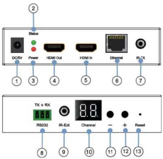
- DC 5V 1A input
- Green indicator of data status
- Red indicator of power input
- HDMI output for local display
- HDMI input
- CAT5e/6 output
- IR-TX
- RS232 port
- IR-Ext
- LED to show the Group ID
- Press the button for the previous Group ID
- Press the button for the next Group ID
- Reset button
NOTE:
- The green LED will blink once the unit is working.
- The LED indicator will glow bright red once the power supply is connected.
RX
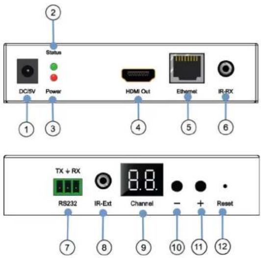
- DC 5V 1A input
- Green indicator of data status
- Red indicator of power input
- HDMI output
- CAT5e/6 input
- IR-RX
- RS232 port
- IR-Ext
- LED to show the Group ID
- Press the button for the previous Group ID
- Press the button for the next Group ID
- Reset button
NOTE:
- The green LED will blink once the unit is working.
- The LED indicator will glow bright red once the power supply is connected.
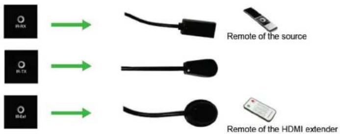
How to connect the IR Cable
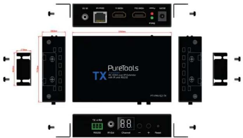
4.1 Panel Drawing
Transmitter
Receiver
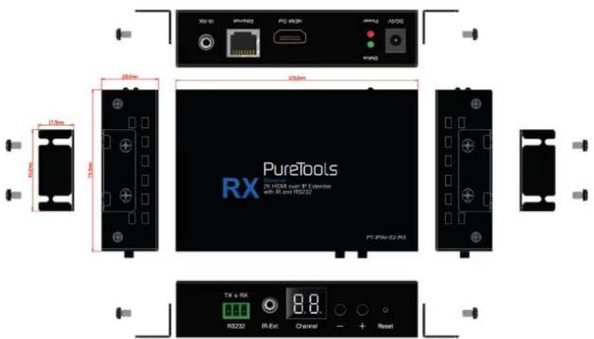
7
5. Installation and Configuration
5.1 Setup HDMI TX and RX
When connecting point to point, no need to configure TX and RX,
When connecting point to many, many to point and many to many, please make sure every TX and RX has unique IP and MAC address, every TX has unique group ID.
Our this over IP Extender has been assigned unique default MAC address for every TX and RX, so you don't have to set the MAC for the units.
You just need to set the IP address and Group ID following bellowing steps.
5.1.1 Setting the IP address
A). DHCP (Dynamic host configuration protocol)
If you are using a Switch that supports DHCP, please enable DHCP so that the Switch will assign an unique IP for TX and RX, and you don't need to change the IP for the units manually.
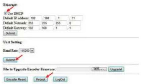
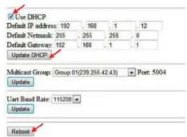
B). Set the IP via web browser
If you are using a Switch that doesn't support DHCP, please change the default IP for TX (192.168.1.11) and RX (192.168.1.12) manually.
A HTTP server is embedded in each TX and RX. You can set up IP address for HDMI Extender via web browser. The default IP address of the TX is 192.168.1.11, user name: admin, password: admin
The default IP address of the RX is 192.168.1.12
Operating Instructions
Step 1:
Make sure the Transmitter and PC are in the same domain.
Access the Network Setting Control Panel in Windows and locate your Lan connection. Under Windows 7, this can be done by clicking Start > Control Panel > Network Sharing center > Change adapter settings > Properties >Internet Protocol Version4 (TCP/IPv4). Change the IP address field to 192.168.1.1 (0-255). After that press „OK“ to save the configuration.
NOTE: The PC and TX/RX should be in the same domain.
The IP address of PC should be different from the IP address of TX and RX.
Step 2:
Use an Ethernet Cable to connect the PC (or laptop) and the extender. the power LED for the extender is red and the green status is blinking.
Step 3:
Login in IE: 192.168.1.11 (default IP for TX) or 192.168.1.12 (default IP for RX), You can setup IP address for the TX and RX. TX requires user name: admin and password: admin
Please set IP address for each TX and each RX, IP: 192.168.1.XX (XX:1-255. all IP address for TX and RX must be different and can't be same as the PC's address.)
Step 4:
After selecting "Use DHCP" or reset the IP Address, click "Submit" (transmitter) or "update DHCP" (Receiver).
Step 5:
Click "Reboot".
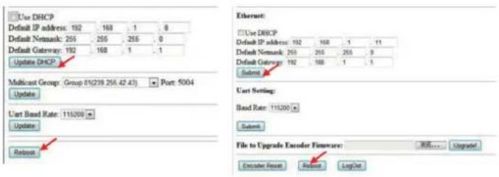
Step 6:
Restart the extender after resting the IP Address.
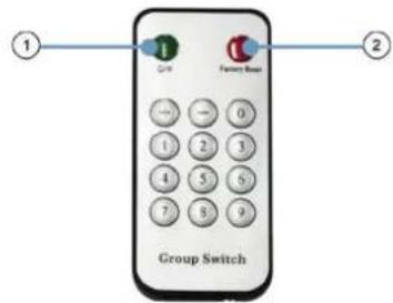
5.1.2 Choose the Group ID and Baud Rate by Remote controller
(When the LED shows "00", it's ready to work)
- Press the button, switch to choose the Group ID or Baud rate.
- Factory reset. Press the button for 3 seconds, the LED will flicker then turn to "00", you have successfully finished the factory reset.
Choose Group ID 00-63
- Press "+" or "-" to change to the previous or next Group ID.
- Press the No to change Group ID. For example, if you need change to 01, press "0", then press "1".
Choose the Baud Rate
Press the Button, switch to Baud Rate mode, press "+" or "-" to change the Baud Rate.
| F0 F1 F2 | F3 F4 F5 F6 F7 | ||||||
| 2400 (default) | 4800 9600 | 0 19200 28800 | 0 38400 57600 | 0 115200 |
3. How to choose the source:
For example, when the connection is:
Source (DVD1) - TX (TX1) - Gigabit Switch - RX (RX1) - TV1
Source (DVD2) - TX (TX2) - Gigabit Switch - RX (RX2) - TV2
Source (DVD3) - TX (TX3) - Gigabit Switch - RX (RX3) - TV3
The group ID of transmitters is:
TX1 (01)
TX2 (02)
TX3 (03)
If you need display Source on TV1, then just set Group ID of RX1 same as TX1: 01(see below picture).


TX 1 RX 1
5.1.3 Set the group ID for TX and RX via web browser
Step 1:
Make sure the Transmitter and PC are in the same domain. (Refer to 5.1.1)
Step 2:
Use an Ethernet Cable to connect the PC (or laptop) and the Extender. the power LED for the extender is red and the green status LED is blinking.
Step 3:
Power on the TX or RX with 5V 1A power supply.
Step 4:
Login in IE: 192.168.1.11 (default IP for TX) or 192.168.1.12 (default IP for RX), TX requires user name: admin and password: admin.
Step5:
Change the group ID at "Stream setting", "00" means group "00" here which can be chosen from 00 to 63.
Step 6:
Click "Submit" (transmitter) or update (receiver).
Stream Setting:
Multicast Group: Group 00(239.255.42.42) ▼ Port: 5004 Update
Transfer: ☑ Multicast
Multicast IP: 00(239.255.42.42) ▼ Port: 5004
Note: When you change the group ID on both Web browser and Remote controller, the units will follow the latest one.
If you change the Group ID on web browser, it can't be shown on the LED.
5.2 Preparing the switch
When doing point to many and many to many, it requires a switch to distribute the sources. We suggest you use the Switch that supports IGMP and DHCP. IGMP feature help to manage the group ID which is related to switch the sources; DHCP allow the switch to assign an IP for TX and RX automatically, please enable DHCP of the switch.
5.3 Connection
Note: Please don't insert into or pull out HDMI cable when power on. Please connect cable only when power is off.
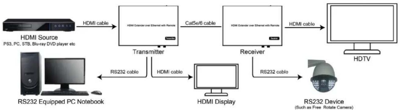
5.3.1 Point to point
- Connect the source device and the Transmitter unit with HDMI Cable.
- Connect the HDMI looping output of the Transmitter to the local HDMI display.
-
- Connect another HDMI display and the HDMI Receiver unit with HDMI Cable.
- Connect the Transmitter and Receiver with Cat5e/6 cable
- Connect the IR TX cable into "IR TX" port of the transmitter; Connect the IR RX cable into "IR RX" port of the receiver. Then you can control the source at the RX side with IR.
- Connect one RS-232 Cable from the PC or automation system to the RS-232 port on the Transmitter; Connect one RS-232 cable from the Receiver to the RS-232 device to be controlled.
- Power on Transmitter and Receiver with adapter 5V 1A.
Note: Insert/Extract cables gently.
flowchart
graph LR
    A["HDMI Source\nPS3, PC, STB, Blu-ray DVD player etc"] -->|HDMI cable| B["Transmitter"]
    B -->|Cat5e/6 cable| C["Receiver"]
    C -->|HDMI cable| D["HDTV"]
    E["RS232 Equipped PC Notebook"] -->|RS232 cable| F["HDMI Display"]
    F -->|RS232 cable| G["RS232 Device\n(Such as Free Rotate Camera)"]
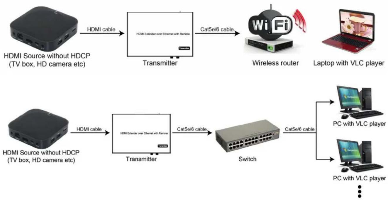
5.3.2 Compatible with Video Player such as VLC etc.
flowchart
graph TD
    A["HDMI Source without HDCP (TV box, HD camera etc)"] -->|HDMI cable| B["Transmitter"]
    B -->|Cat5e/6 cable| C["Wireless router"]
    C --> D["Laptop with VLC player"]
    E["HDMI Source without HDCP (TV box, HD camera etc)"] -->|HDMI cable| F["Transmitter"]
    F -->|Cat5e/6 cable| G["Switch"]
    G --> H["PC with VLC player"]
    G --> I["PC with VLC player"]
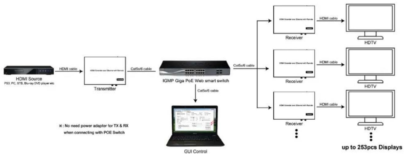
5.3.3 Point to many
- Setting the IP address for Transmitter & Receiver and preparing the switch following the steps as instructed above (5.1.1&5.2)
- Connect the source device and the Transmitter unit with HDMI Cable.
- Connect the HDMI looping output of the Transmitter to the local HDMI Display.
- Connect the transmitter and the switch/router with cat5e or cat6 cable.
- Connect all the Receivers and the switch/ router with Cat5e/6 cable.
- Connect the HDMI displays and the HDMI Receiver units with HDMI Cable.
- Connect the IR TX cable into "IR TX" port of the transmitter; Connect the IR RX cable into "IR RX" port of the receiver. Then you can control the source at the RX side with IR.
- Connect one RS-232 Cable from the PC or automation system to the RS-232 port on the Transmitter; Connect one RS-232 cable from the Receiver to the RS-232 device to be controlled.
- Power on Transmitter and Receiver with adapter 5V1A, power on the switch with its adapter.
Note: Daisy chain the switch if its RJ45 port is not enough.
The quantity of Receiver is up to 255pcs.
flowchart
graph LR
    A["HDMI Source PS3, PC, STB, Bu-ray DVD player etc"] -->|HDMI cable| B["Transmitter"]
    B -->|Cat5e/6 cable| C["IGMP Giga PoE Web smart switch"]
    C -->|Cat5e/6 cable| D["GUI Control"]
    D --> E["+ up to 253pcs Displays"]

    subgraph HDTV
        F["HDMI Cable"] --> G["HDTV"]
    end

    H["HDMI Cable"] --> I["HDMI Cable"]
    J["HDMI Cable"] --> K["HDTV"]
    L["HDMI Cable"] --> M["HDTV"]
    N["HDMI Cable"] --> O["HDTV"]
    P["HDMI Cable"] --> Q["HDTV"]
    R["HDMI Cable"] --> S["HDTV"]
    T["HDMI Cable"] --> U["HDTV"]
    V["HDMI Cable"] --> W["HDTV"]
    X["HDMI Cable"] --> Y["HDTV"]
    Z["HDMI Cable"] --> AA["HDTV"]
    AB["HDMI Cable"] --> AC["HDTV"]
    AD["HDMI Cable"] --> AE["HDTV"]
    AF["HDMI Cable"] --> AG["HDTV"]
    AH["HDMI Cable"] --> AI["HDTV"]
    AJ["HDMI Cable"] --> AK["HDTV"]
    AL["HDMI Cable"] --> AM["HDTV"]
    AN["HDMI Cable"] --> AO["HDTV"]
    AP["HDMI Cable"] --> AQ["HDTV"]
    AR["HDMI Cable"] --> AS["HDTV"]
    AT["HDMI Cable"] --> AU["HDTV"]
    AV["HDMI Cable"] --> AW["HDTV"]
    AX["HDMI Cable"] --> AY["HDTV"]
    AZ["HDMI Cable"] --> BA["HDTV"]
    BB["HDMI Cable"] --> BC["HDTV"]
    BD["HDMI Cable"] --> BE["HDTV"]
    BF["HDMI Cable"] --> BG["HDTV"]
    BH["HDMI Cable"] --> BI["HDTV"]
    BJ["HDMI Cable"] --> BK["HDTV"]
    BL["HDMI Cable"] --> BM["HDTV"]
    BN["HDMI Cable"] --> BO["HDTV"]
    BP["HDMI Cable"] --> BQ["HDTV"]
    BR["HDMI Cable"] --> BS["HDTV"]
    BT["HDMI Cable"] --> BU["HDTV"]
    BV["HDMI Cable"] --> BW["HDTV"]
    BX["HDMI Cable"] --> BY["HDTV"]
    BZ["HDMI Cable"] --> CA["HDTV"]
    AZH["HDMI Cable"] --> CB["HDTV"]
    CC["HDMI Cable"] --> CD["HDTV"]
    CE["HDMI Cable"] --> CF["HDTV"]
    DG["HDMI Cable"] --> DH["HDTV"]
5.3.4 Many to many
- Setting the IP address for Transmitter & Receiver and preparing the switch following the steps as instructed above (5.1.1&5.2)
- Connect the source device and the Transmitter unit with HDMI Cable.
- Connect the HDMI looping output of the Transmitter to the local HDMI Display.
- Connect the transmitters and the switch/router with cat5e or cat6 cable
- Connect the Receivers and the switch/ router with Cat5e/6 cable
- Connect the HDMI displays and the HDMI Receiver units with HDMI Cable.
- Connect the IR TX cable into "IR TX" port of the transmitter; Connect the IR RX cable into "IR RX" port of the receiver. Then you can control the source at the RX side with IR.
- Connect one RS-232 Cable from the PC or automation system to the RS-232 port on the Transmitter; Connect one RS-232 cable from the Receiver to the RS-232 device to be controlled.
- Power on Transmitter and Receiver with adapter 5V1A, power on the switch with its adapter.
- Choose the source by Remote controller or Web browser as instructed above (5.1.2)
Note: Daisy chain the switch if its RJ45 port is not enough.
The quantity of Transmitter is no more than 64 pcs.
The total quantity of Transmitter and Receiver is less than 256 pcs
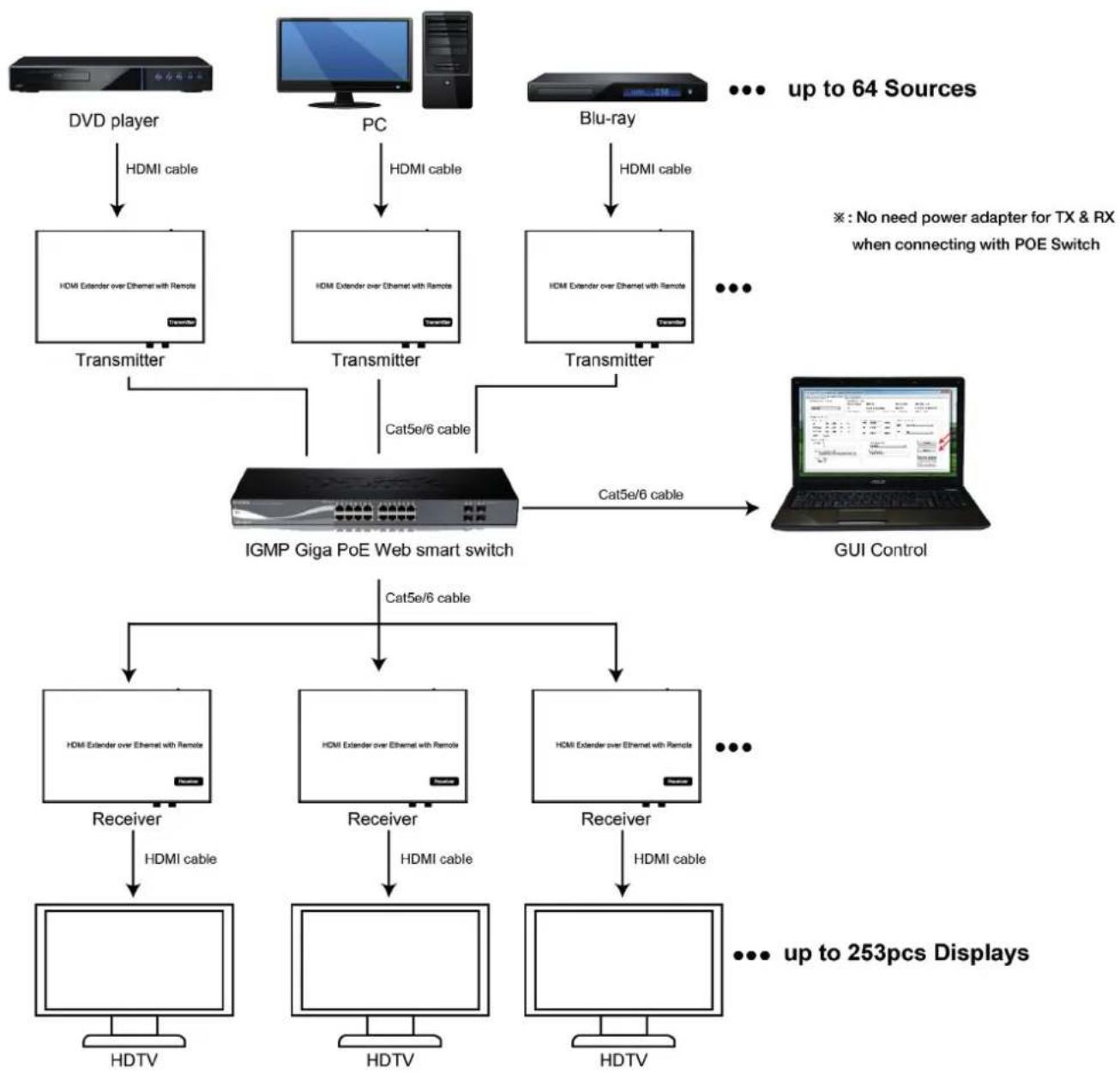
flowchart
graph TD
    A[" DVD player "] -->|HDMI cable| B[" HDMI Extender over Ethernet with Remote"]
    C[" PC "] -->|HDMI cable| D[" HDMI Extender over Ethernet with Remote"]
    E[" Blu-ray "] -->|HDMI cable| F[" HDMI Extender over Ethernet with Remote"]
    B --> G[" Transmitter "]
    D --> H[" Transmitter "]
    F --> I[" Transmitter "]
    G --> J[" IGMP Giga PoE Web smart switch "]
    H --> J
    I --> J
    J --> K[" Cat5e/6 cable "]
    K --> L[" GUI Control "]
    M[" HDMI Cable"] --> N[" HDMI Extender over Ethernet with Remote"]
    O[" HDMI Cable"] --> P[" HDMI Extender over Ethernet with Remote"]
    Q[" HDMI Cable"] --> R[" HDMI Cable"]
    S[" HDMI Cable"] --> T[" HDMI Cable"]
    U[" HDMI Cable"] --> V[" HDMI Cable"]
    W[" HDMI Cable"] --> X[" HDMI Cable"]
    Y[" HDMI Cable"] --> Z[" HDMI Cable"]
    AA[" HDMI Cable"] --> AB[" HDMI Cable"]
    AC[" HDMI Cable"] --> AD[" HDMI Cable"]
    AE[" HDMI Cable"] --> AF[" HDMI Cable"]
    AG[" HDMI Cable"] --> AH[" HDMI Cable"]
    AI[" up to 64 Sources "]
    AJ[" * : No need power adapter for TX & RX when connecting with POE Switch "]
    AK[" ... up to 253pcs Displays "]
Note: The total qty of TX, RX, Switch is less than 256pcs.
6. RS232 and Baud rate
The unit provides a path to pass through the RS232 signal, RS232 passes from TX to RX or from RX to TX, connect to your RS232 devices, such as PC, IP Camera, Creston control panel, Smart Matrix, printer and Scanner and so on. It works when TX, RX and your RS232 devices baud rate is the same. The default baud rate of TX and RX is 2400 which is frequently used for most devices.
6.2 Baud rate setting
6.2.1 Setting the Baud rate via Web Browser
Login TX and RX with their default IP (TX: 192.168.1.11; RX: 192.168.1.12) to modify the Baud Rate which range from default 2400 to 115200.
Uart Setting:
Baud Rate: 115200
Note: When you change the Baud rate on both Web browser and Remote controller, the units will follow the latest one.
Please send the data in the same group ID.
7. Firmware update
We provide the firmware to upgrade the units when it is necessary. Please follow up bellowing steps to update the firmware.
Step1:
Connect TX / RX to the PC with a short Cat5e cable
Step2:
Power on TX/ RX with power adapter 5V1A.
Step3:
Login TX or RX with their default IP (TX: 192.168.1.11; RX: 192.168.1.12) on web browser, TX requires user name: admin and password: admin
Step4:
Click "choose File" on the interface and find out the latest version firmware
Step5:
Click "Upgrade", the process will takes seconds, please DO NOT interrupt or power off the units during the time.
File to Upgrade Firmware:
Choose File No file chosen
Upgrade!
8. One key recovery to default setting

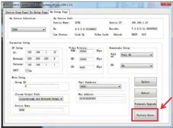
9. PC Tool Instructions
Step 1:
Make sure the Transmitter and PC are in the same domain. (Refer to 5.1.1)
Step 2:
Open the PC Tool.
Step 3:
Click "Start Scan".

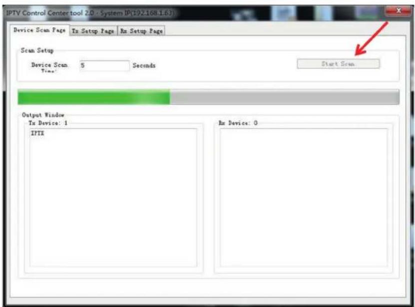
Step 4:
Choose the TX or RX Name.
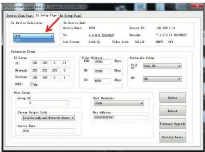
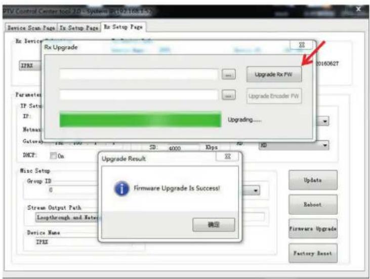
9.1 Firmware Upgrade
Upgrade for TX
Step 1:
Click "Firmware Upgrade".
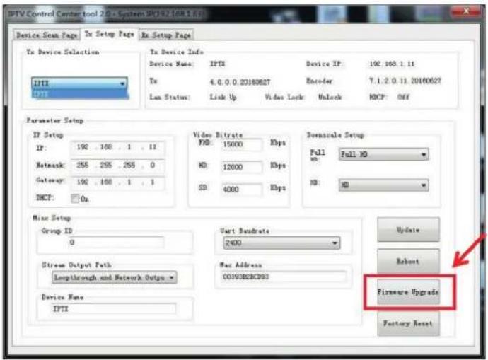
Step 2:
Click "Upgrade Encoder FW" first.
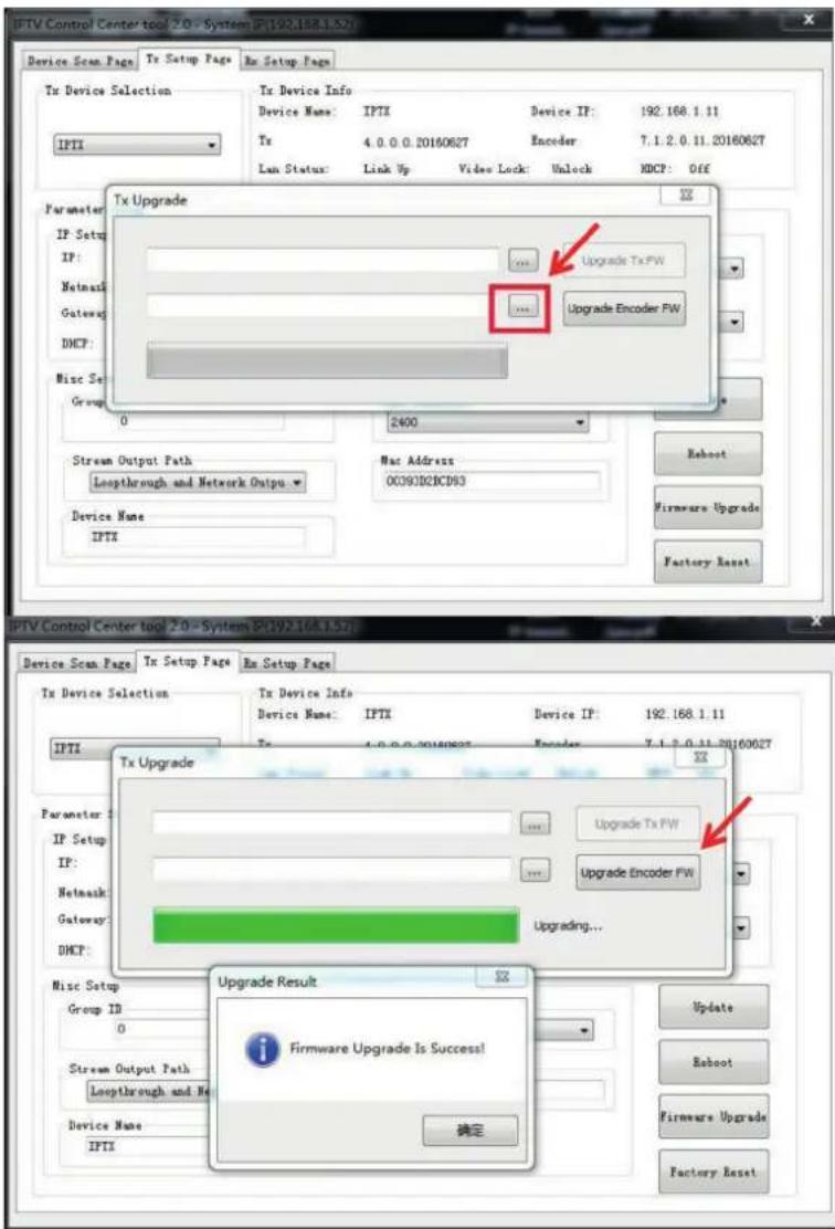
Step 3:
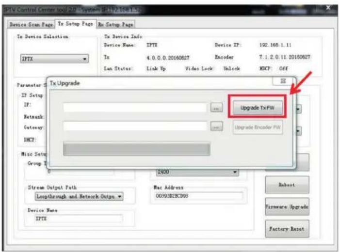
After the step 2 is finished, click "Firmware Upgrade" again, then click "Upgrade TX FW".
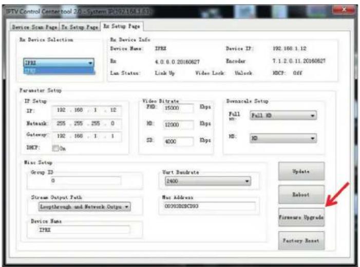
Upgrade for RX
Step 1:
Click "Firmware Upgrade".
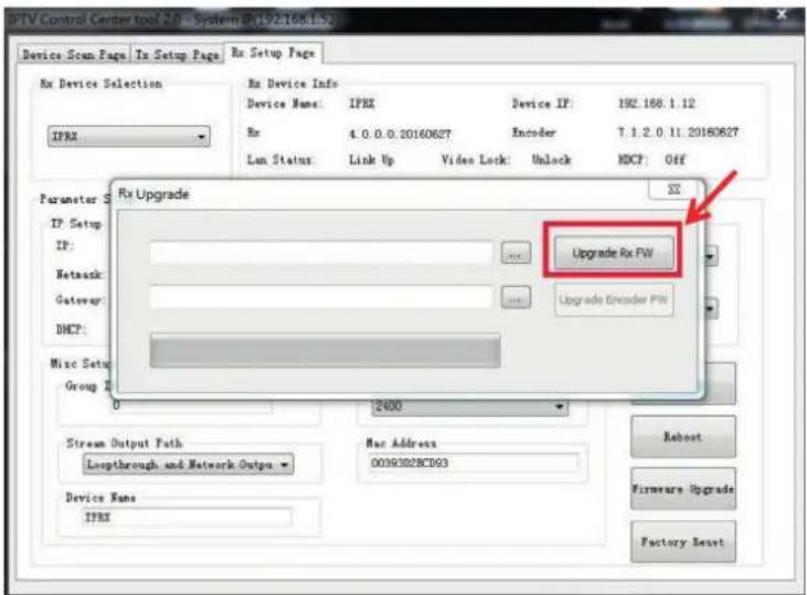
Step 2:
Click "Upgrade Rx FW".
9.2 Other settings
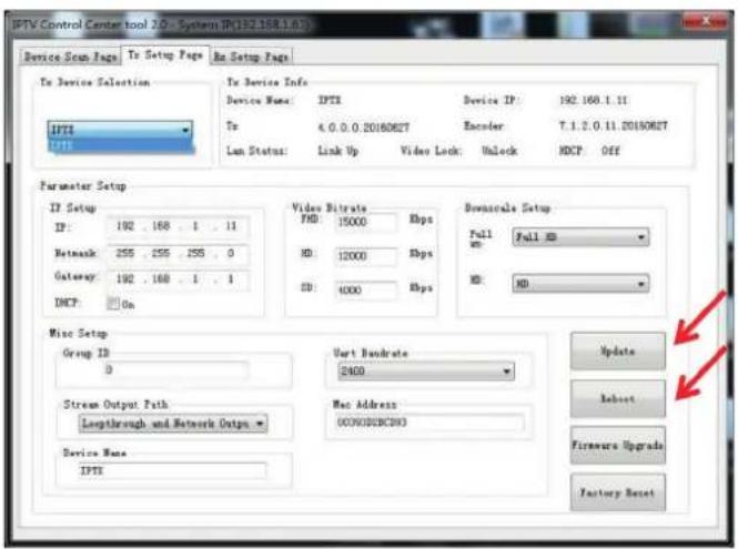
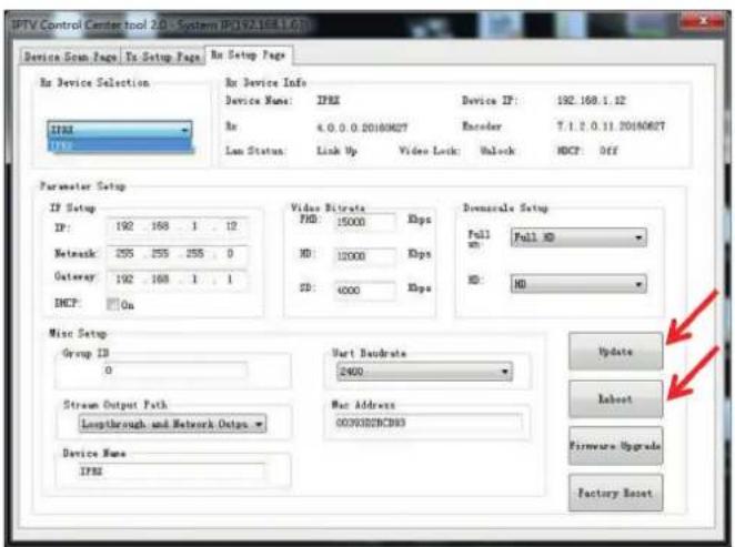
Step 1:
Change the
IP/Netmask/Gateway/DHCP/
Uart Baudrate/Group ID/Mac Address/
Device name
on the PC tool interface.
Step 2:
Click "Update",
after "Update" is finished,
click "Reboot".
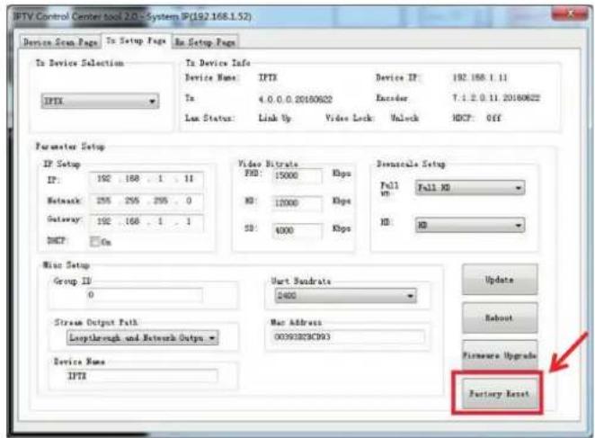
9.2 Click "Factory Reset" on TX or RX.
10. After sale Service and Warranty.
11. How to use VLC
Step 1:
Make sure the Transmitter and PC are in the same domain.
(Refer to 5.1.1)
Step 2:
Connect the HDMI Source without HDCP with the transmitter and power on the device.
Step 3:
Connect the transmitter to the PC.
Step 4:
Check the Multicast Group on the web (refer to 5.1.3).
Step 5:
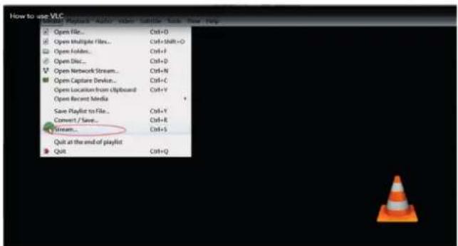
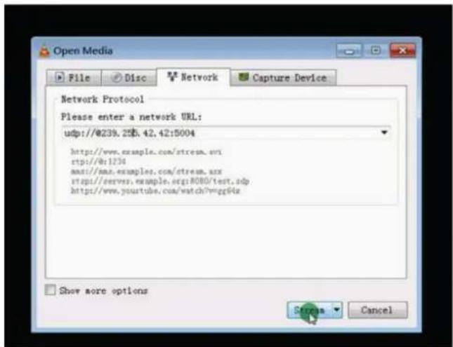
Open the VLC media Player, click "Stream"> "Network", Input "UDP://@239.255.42.42:5004"
Note: 239.255.42.42 (Multicast Group) 5004 (Port)
Step 6:
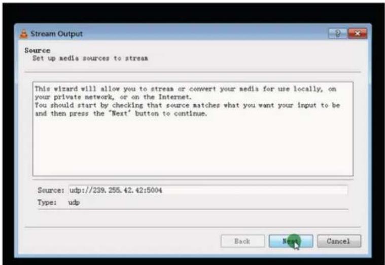
Click "Next".
Step 7:
Choose "RTP / MPEC Transport Stream".
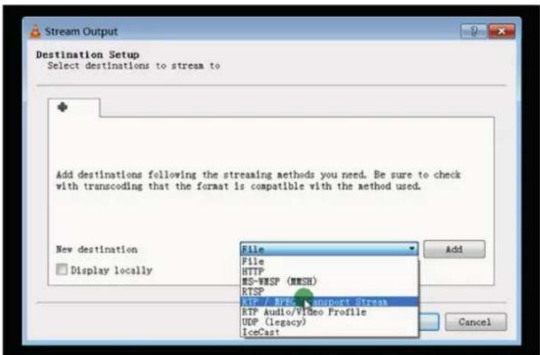
Step 8:
Click "Next".
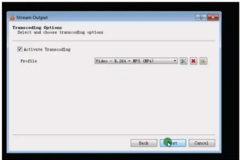
Step 9:
Click "Stream".
![Stream Output Option Setup Set up any additional options for streaming Miscellaneous Options Stream all elementary streams Generated stream output string :sout=#transcode[vcodec=h/屏幕录像专家 未注册 8, channels=2, samplerate=44100] :sout-keep Back Stream Cancel](/content/2026/05/797673/images/7d5c0a7a97659a50ef1ae62d1c0e13030d6f31a44be4c272094e3ae02731d25e.jpg)
Step 10:
Click "Open Network Stream", then you can click "Play" to view the video.
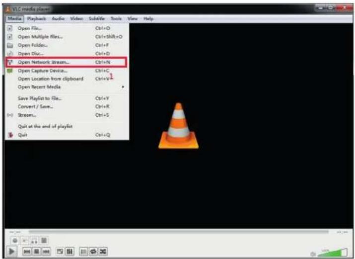

WARRANTY
If your product does not work properly because of a defect in materials or workmanship, our Company (referred to as „the warrantor“) will, for the length of the period indicated as below, (Parts(2)Year, Labor(90) Days) which starts with the date of original purchase („Limited Warranty period“), at its option either(a) repair your product with new or refurbished parts, or (b) replace it with a new of a refurbished product. The decision to repair or replace will be made by the warrantor.
During the „Labor“ Limited Warranty period there will be no charge for labor.
During the „Parts“ warranty period, there will be no charge for parts. You must mail-in your product during the warranty period. This Limited Warranty is extended only to the original purchaser and only covers product purchased as new. A purchase receipt or other proof of original purchase date is required for Limited Warranty service.
MAIL-IN SERVICE
When shipping the unit carefully pack and send it prepaid, adequately insured and preferably in the original carton. Include a letter detailing the complaint and provide a day time phone and/or email address where you can be reached.
LIMITED WARRANTY LIMITS AND EXCLUSIONS
a. This Limited Warranty ONLY COVERS failures due to defects in materials or workmanship, and DOES NOT COVER normal wear and tear or cosmetic damage. The Limited Warranty ALSO DOES NOT COVER damages which occurred in shipment, or failures which are caused by products not supplied by warrantor, or failures which result from accidents, misuse, abuse, neglect, mishandling, misapplication, alteration, faulty installation, set-up adjustments, misadjustment of consumer controls, improper maintenance, power line surge, lightning damage, modification, or service by anyone other than a Factory Service center or other Authorized Server, or damage that is attributable to acts of God.
b. THERE ARE NO EXPRESS WARRANTIES EXCEPT AS LISTED UNDER „LIMITED WARRANTY COVERAGE“. THE WARRANTOR IS NOT LIABLE FOR INCIDENTAL OR CONSEQUENTIAL DAMAGES RESULTING FROM THE USE OF THIS PRODUCT, OR ARISING OUT OF ANY BREACH OF THIS WARRANTY. (As examples, this excludes damages for lost time, cost of having someone remove or re-install an installed unit if applicable, travel to and from the service, loss of or damage to media or images, data or other recorded content. The items listed are not exclusive, but are for illustration only.)
c. PARTS AND SERVICE, WHICH ARE NOT COVERED BY THIS LIMITED WARRANTY, ARE YOUR RESPONSIBILITY.
Asking for Assistance
Technical Support:
Phone: +49 5971 800299 - 0
Fax: +49 5971 800299 - 99
Technical Support Hours:
8:30 AM to 5:00 PM Monday thru Thursday
8:30 AM to 4:00 PM Friday
Write To:
PureLink GmbH


- User Manual
- Introduction
- Features
- Package Contents TX
- Package Contents RX
- Panel description
- NOTE:
- Panel Drawing
- Receiver
- Installation and Configuration
- Setup HDMI TX and RX
- Setting the IP address
- A). DHCP (Dynamic host configuration protocol)
- B). Set the IP via web browser
- Step 1:
- Step 2:
- Step 3:
- Step 4:
- Step 5:
- Step 6:
- Choose the Group ID and Baud Rate by Remote controller
- Choose Group ID 00-63
- Choose the Baud Rate
- How to choose the source:
- Set the group ID for TX and RX via web browser
- Step5:
- Preparing the switch
- Connection
- Point to point
- Compatible with Video Player such as VLC etc.
- Point to many
- Many to many
- RS232 and Baud rate
- Baud rate setting
- Setting the Baud rate via Web Browser
- Firmware update
- Step1:
- Step2:
- Step3:
- Step4:
- One key recovery to default setting
- PC Tool Instructions
- Firmware Upgrade
- Upgrade for TX
- Upgrade for RX
- Other settings
- Click "Factory Reset" on TX or RX.
- After sale Service and Warranty.
- How to use VLC
- Step 7:
- Step 8:
- Step 9:
- Step 10:
- WARRANTY
- MAIL-IN SERVICE
- LIMITED WARRANTY LIMITS AND EXCLUSIONS
- Asking for Assistance
Brand : PureLink
Model : PT-IPAV-E2-TX
Category : Audio/video extender