
IPCB72520 - Security Camera ABUS - Free user manual and instructions
Find the device manual for free IPCB72520 ABUS in PDF.


| Product Type | Security Camera (IP) |
| Model | IPCB72520 |
| Power Supply | 12 V DC or PoE 802.3af |
| Network Connector | RJ45, PoE |
| Video Output | Analog BNC (service only) |
| Audio Input | MIC/LINE (2-2.4 Vss, 1 KΩ) |
| Audio Output | Line out, 600 Ω impedance, 20 mW @ 16Ω |
| Switching Input | 1 alarm input (dry contact) |
| Switching Output | 1 alarm output, 12 V DC, max. 30 mA |
| Storage | Micro SD card slot (card not included) |
| Reset | Hardware reset button (hold 30 s) |
| Zoom & Focus | Remote control via web interface |
| IR Illuminators | Built-in IR LEDs, range dependent on environment |
| Indoor/Outdoor | Indoor and outdoor use (depending on model) |
| Compliance | EMC Directive 2014/30/EU, RoHS 2011/65/EU |
| Maintenance | No user-serviceable parts; clean with dry cloth |
| Repairability | No spare parts available; do not open |
| Disposal | WEEE symbol: do not dispose with household waste |
| Operating Conditions | Avoid moisture, extreme heat/cold, dust, vibrations |
Frequently Asked Questions - IPCB72520 ABUS
User questions about IPCB72520 ABUS
0 question about this device. Answer the ones you know or ask your own.
Ask a new question about this device
Download the instructions for your Security Camera in PDF format for free! Find your manual IPCB72520 - ABUS and take your electronic device back in hand. On this page are published all the documents necessary for the use of your device. IPCB72520 by ABUS.
USER MANUAL IPCB72520 ABUS
IPCB72520 / IPCB74520 / IPCB78520

natural_image
Close-up of a black-and-white A815 surveillance camera with blue-lit sensor and camera lens (no text or symbols visible)natural_image
Technical line drawing of a mechanical component with circular and rectangular features (no text or symbols)natural_image
Technical line drawing of a mechanical component with concentric circular features and mounting holes (no text or symbols)
natural_image
Close-up of a Huawei AV security camera with visible lens and control buttons (no text or symbols on body)Installation manual
Version 12/2018
CE
English translation of the original German user manual. Retain for future reference.
Dear Customer,
Thank you for purchasing this product.
IPCB72520
This device complies with the requirements of the following EU directives: the EMC Directive (2014/30/EU) and the RoHS Directive (2011/65/EU).
IPCB74520
This device complies with the requirements of the following EU directives: the EMC Directive (2014/30/EU) and the RoHS Directive (2011/65/EU).
IPCB78520
This device complies with the requirements of the following EU directives: the EMC Directive (2014/30/EU) and the RoHS Directive (2011/65/EU).
To ensure this condition is maintained and that safe operation is guaranteed, it is your obligation to observe this user manual.
Please read the entire user manual carefully before putting the product into operation, and pay attention to all operating instructions and safety information.
All company names and product descriptions are trademarks of the corresponding owner. All rights reserved.
If you have any questions, please contact your specialist installation contractor or specialist dealer.

Disclaimer
This user manual has been produced with the greatest of care. Should you discover any missing information or inaccuracies, please let us know about them.
ABUS Security-Center GmbH & Co. KG does not accept any liability for technical and typographical errors, and reserves the right to make changes to the product and user manuals at any time and without prior warning.
ABUS Security-Center GmbH is not liable or responsible for any direct or indirect damage resulting from the installation, performance and use of this product. No guarantee is made for the contents of this document.
Important safety information
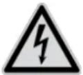
All guarantee claims are invalid in the event of damage caused by non-compliance with this user manual. We cannot be held liable for resulting damage.

We cannot be held liable for material or personal damage caused by improper operation or non-compliance with the safety information. All guarantee claims are void in such cases.
Dear Customer,
The following safety information and hazard notes are not only intended to protect your health but also to protect the device from damage. Please read the following points carefully:
- There are no components inside the product that require maintenance by the operator. Opening or dismantling the product invalidates the CE certification and guarantee claims/warranty.
- The product may be damaged if it is dropped, even from a low height.
Avoid the following adverse conditions during operation:
- Moisture or excess humidity
• Extreme heat or cold - Direct sunlight
- Dust or flammable gases, vapours or solvents
- Strong vibrations
• Strong magnetic fields (e.g. next to machines or loudspeakers) - The camera must not be installed on unstable surfaces.
General safety information:
- Do not leave packaging material lying around. Plastic bags, sheeting, polystyrene packaging, etc. can pose a danger to children if played with.
- The video surveillance camera contains small parts which could be swallowed and must be kept out of the reach of children for safety reasons.
- Do not insert any objects into the device through the openings.
- Only use replacement devices and accessories that are approved by the manufacturer. Do not connect any non-compatible products.
- Please pay attention to the safety information and user manuals for the other connected devices.
- Check the device for damage before putting it into operation. Do not put the device into operation if you identify any damage.
- Adhere to the normal voltage limits specified in the technical data. Higher voltages could destroy the device and pose a health risk (electric shock).

When installing the device in an existing video surveillance system, ensure that all devices have been disconnected from the mains power circuit and low-voltage circuit.

If in doubt, have a specialist technician carry out assembly, installation and connection of the device. Improper or unprofessional work on the power supply system or domestic installation puts both you and other persons at risk.
Connect the installations so that the mains power circuit and low-voltage circuit always run separately
from each other. They should not be connected at any point or become connected as a result of a malfunction.
Contents
- INTENDED USE 14
- EXPLANATION OF SYMBOLS 14
- CONNECTIONS AND FUNCTIONS.... 15
3.1 CONNECTIONS.... 15
3.2 CALL FACTORY DEFAULT SETTINGS (RESET) 15
3.3 SD CARD SLOT 16
3.4 ANALOG VIDEO OUTPUT 16
3.5 ZOOM AND FOCUS SETTING 17
3.6 SWITCHING INPUT/OUTPUT 17
3.7 AUDIO INPUT / AUDIO OUTPUT.... 18
3.8 NOTES TO THE USAGE OF INTERNAL IR LEDs 18
- MAINTENANCE AND CLEANING.... 19
4.1 FUNCTION TEST 19
4.2 CLEANING 19
- DISPOSAL 19
1. Intended use
This camera is used for indoor and outdoor video surveillance (depending on the model) in conjunction with a recording device or appropriate display unit (e.g. PC).

Use of this product for any other purpose than that described may lead to damage to the product and other hazards. All other uses are not as intended and will result in the invalidation of the product guarantee and warranty. No liability can be accepted as a result. This also applies to any alterations or modifications made to the product.
Read the user guide carefully and in full before putting the product into operation. The user guide contains important information on installation and operation.
2. Explanation of symbols
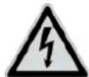
The triangular high voltage symbol is used to warn of the risk of injury or health hazards (e.g. caused by electric shock).

The triangular warning symbol indicates important notes in this user manual which must be observed.

This symbol indicates special tips and notes on the operation of the device.

This user manual describes the software functions in the camera browser interface. For information about how to install the hardware for the respective camera, please read the quick start manual or the hardware installation manual, if you have it.
You can download a PDF version of the user manuals in your language at www.abus.com via the product search.
3. Connections and functions
3.1 Connections
 | ATTENTION!Before you begin the installation, make sure that the supply voltage and the nominal voltage of the camera match. | |
 | 1: Network connector (RJ45, PoE 802.3af)2: Power connector, 12 V DC, ensure that the polarity is correct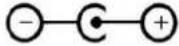 3: “AUDIO” (audio input, audio output)4: Analog video output for service purpose5: “ALARM” (switching input, switching output) 3: “AUDIO” (audio input, audio output)4: Analog video output for service purpose5: “ALARM” (switching input, switching output) | |
3.2 Call factory default settings (Reset)
- Please disconnect the camera form power connection.
- Press the "Reset" button on the camera and keep it pressed.
- Now connect the power supply to the camera (power supply or Power over Ethernet), and hold the "Reset" button pressed for another 30 seconds.

natural_image
Technical line drawing of a mechanical component with concentric circular features and mounting holes (no text or symbols)3.3 SD card slot
natural_image
Technical line drawing of a mechanical component with concentric circular features and mounting holes (no text or symbols)
Before usage of micro SD card the card must be formatted.
3.4 Analog video output
The analog video output is located at the connection cable of the camera (BNC connector). The analog video output is designed for service purposes such as adjusting the lens.

3.5 Zoom and focus setting
Zoom and focus are controlled remotely over web interface of the camera. During installation only the view direction need to be adjusted.
3.6 Switching input/output

The maximum load values must be observed, otherwise, the camera may be irreparably damaged.
| Description Connection information | ||
| Switching input „IN“ Bridge between „IN“ and „G“ | ||
| „G“(GND) |  | |
| Switching output „OUT“ 12 V DC, max. 30 mA, please note the connection polarity | ||
| „G“(GND) |  | |
3.7 Audio input / audio output
| Description Connection information | ||
| Audio input „IN“ MIC / LINE Interface | LINE: 2-2.4Vss, 1KΩ | |
| „G“ (GND) | ||
| Audio output „OUT“ Impedance: 600 Ω | ||
| „G“ (GND) | Frequency range: 20 Hz – 20 kHzOutput power: 20 mW @ 16Ω | |
3.8 Notes to the usage of internal IR LEDs
 | The IR range is strongly dependent on the environmental conditions. If the area in the camera's field of view reflects poorly or if there are no objects within the max. illumination range, the brightness of the video image at night may be too low. This will result in poor usability of the video image.In addition, when installing the camera it must be ensured that no objects are located in close proximity to the camera's field of view (e.g. roof gutter or wall). These objects can reflect back the IR light, resulting in circular fading on the video image in the opposite direction to the object.The IR range might be reduced as well by strong absorbing surfaces (e.g. asphalt). |
4. Maintenance and cleaning
4.1 Function test
Regularly check the technical safety of the product, e.g. check the housing for damage.
If it appears to no longer be possible to operate the product safely, stop using it and secure it to prevent unintentional use.
It is likely that safe operation is no longer possible in the event that:
- the device shows signs of visible damage
- the device no longer works correctly
• the device has been stored in adverse conditions for a long period of time - the device has been exposed to stresses during transportation.

Please note:
You do not need to perform any maintenance on the product. There are no components requiring servicing or checking inside the product. Never open it.
4.2 Cleaning
Clean the product with a clean, dry cloth. The cloth can be dampened with lukewarm water to remove stubborn dirt.

Make sure that no liquids enter the inside of the device, as this will destroy it. Do not use any chemical cleaning agents, as these could damage the surface of the housing.
5. Disposal

Devices displaying this symbol may not be disposed of with domestic waste. At the end of its service life, dispose of the product according to the applicable legal requirements.
Please contact your dealer or dispose of the products at the local collection point for electronic waste.


- IPCB72520 / IPCB74520 / IPCB78520
- Installation manual
- IPCB72520
- IPCB74520
- IPCB78520
- Disclaimer
- Important safety information
- Dear Customer,
- Contents
- Intended use
- Explanation of symbols
- Connections and functions
- Connections
- Call factory default settings (Reset)
- SD card slot
- Analog video output
- Zoom and focus setting
- Switching input/output
- Audio input / audio output
- Notes to the usage of internal IR LEDs
- Maintenance and cleaning
- Function test
- Please note:
- Cleaning
- Disposal
Brand : ABUS
Model : IPCB72520
Category : Security Camera