Flush 36-6462 - Lighting North Light - Free user manual and instructions
Find the device manual for free Flush 36-6462 North Light in PDF.


User questions about Flush 36-6462 North Light
0 question about this device. Answer the ones you know or ask your own.
Ask a new question about this device
Download the instructions for your Lighting in PDF format for free! Find your manual Flush 36-6462 - North Light and take your electronic device back in hand. On this page are published all the documents necessary for the use of your device. Flush 36-6462 by North Light.
USER MANUAL Flush 36-6462 North Light
natural_image
Two overlapping circular objects with gradient shading, no text or symbols visibleArt.no. Model
36-6461 H-CL-RI10W-S827-DI (Silver)
36-6463 H-CL-RI10W-W827-DI (White)
36-6462 H-CL-RI15W-S827-DI (Silver)
36-6464 H-CL-RI15W-W827-DI (White)
Flush Ceiling Light
Art.no 36-6461 Model H-CL-RI10W-S827-DI (Silver)
36-6463 H-CL-RI10W-W827-DI (White)
36-6462 H-CL-RI15W-S827-DI (Silver)
36-6464 H-CL-RI15W-W827-DI (White)
Please read the entire instruction manual before using the product and then save it for future reference. We reserve the right for any errors in text or images and any necessary changes made to technical data. If you have any questions concerning technical problems please contact our Customer Services Department (see address on reverse.)
Safety
- This flush ceiling light is designed for fixed installation.
• Installation should only be carried out by a qualified electrician.
Warning symbol
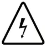
The light bulb of the light fitting must only be replaced by a qualified electrician.
Care and maintenance
- Switch off the power to the light fitting before cleaning it.
- Clean the light using a soft, damp cloth. Use a mild detergent. Never use solvents or strong, abrasive cleaning agents.
Product description
Flush ceiling light fitting with built-in LED bulb and suitable for mounting onto a ceiling or wall.
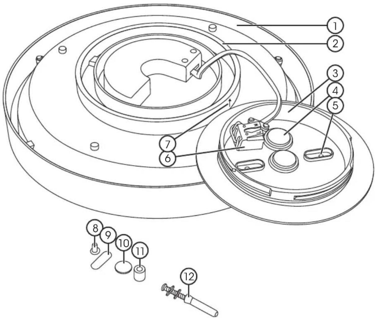
text_image
Technical diagram of a mechanical assembly with numbered components and exploded view indicators- Light fitting
- Gasket
- Mounting plate
- Grommets
- Marks for screw holes (ceiling pattress mounting)
- Terminal block for power supply cable
- Marks for attaching the light fitting to the mounting plate
- Extra screws for the ceiling pattress (2 ×)
- Washers for mounting onto a ceiling pattress (2 ×)
- Self-adhesive tape for the spacers on the mounting plate (3 x)
- Spacers (3 ×)
- Screw with steel washer, soft washer and wall plug (3 ×)
Installation
The light fitting can be installed in one of several ways:
A) Mounted onto a recessed ceiling pattress
Warning: Always turn off the power before beginning the installation.

text_image
! ON OFF ✓-
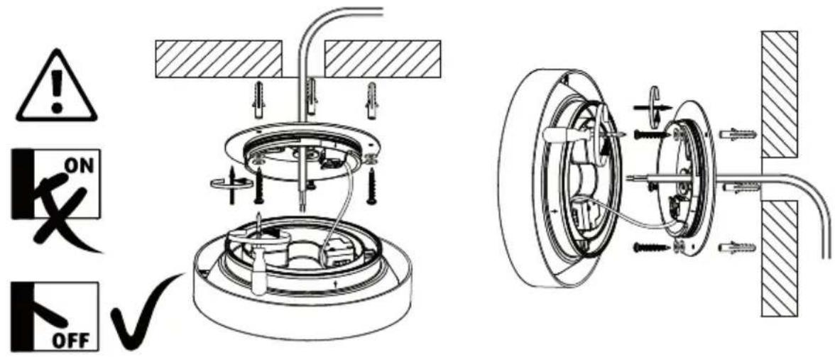
The mounting plate is prepared for attachment to a ceiling pattress. Measure the distance between the screws in the ceiling pattress and drill corresponding holes in the mounting plate. The mounting plate already has mounting hole markings (5) for the most common ceiling pattresses. Make a hole for the screws in the washers (9).
-
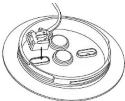
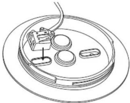
Pull the power supply cable through one of the grommets (4). Fit the gasket (2) onto the light fitting (1).
natural_image
Technical line drawing of a mechanical assembly with no visible text or symbols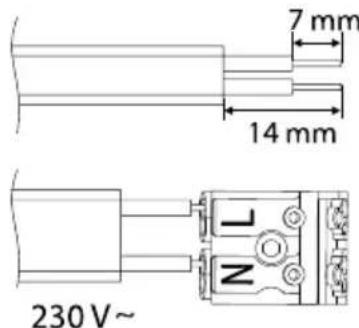
text_image
7 mm 14 mm 230 V~ N-
Screw the mounting plate to the ceiling pattress using the washers (9) as shown.
-
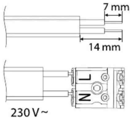
Strip the end of the power cable as shown and connect it to the terminal block (6). Blue wire to N and phase wire to L. The light fitting is rated protection class II □ and does not require a safety connection to electrical earth.
-
Make sure that the gasket (2) is fitted correctly and that the cables don't get crushed between the mounting plate and the light fitting.
-
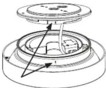
Push the light fitting onto the mounting plate so that the markings (7) line up, then twist the light fitting anticlockwise until it locks into place.
natural_image
Technical diagram of a mechanical assembly with no visible text or symbolsB) Mounted directly onto a ceiling or wall
Warning: Always turn off the power before beginning the installation.
text_image
! ON OFF- The positions of the mounting holes are marked on the mounting plate. Drill mounting holes in the marked positions.
- Use the mounting plate as a template and mark where the holes are to be drilled on the wall or ceiling. Use an appropriate size of drill bit.
- Pull the power supply cable through one of the grommets (4). Fit the gasket (2) onto the light fitting (1).
- Screw on the mounting plate using the fasteners (12). The soft washer should be placed closest to the mounting plate.
text_image
7 mm 14 mm 230 V~ Z- Strip the end of the power cable as shown and connect it to the terminal block (6). Blue wire to N and phase wire to L. The light fitting is rated protection class II □ and does not require a safety connection to electrical earth.
- Make sure that the gasket (2) is fitted correctly and that the cables don't get crushed between the mounting plate and the light fitting.
natural_image
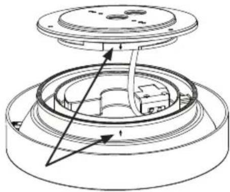
Technical line drawing of a mechanical assembly with no visible text or symbols- Push the light fitting onto the mounting plate so that the markings (7) line up, then twist the light fitting anticlockwise until it locks into place.
C) Mounted on a ceiling/wall with surface mounted cable
Warning: Always turn off the power before beginning the installation.
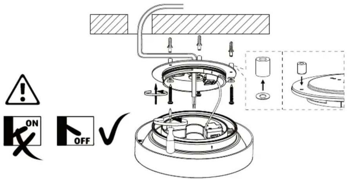
text_image
! ON OFF ✓- The positions of the mounting holes are marked on the mounting plate. Drill mounting holes in the marked positions.
- Use the mounting plate as a template and mark where the holes are to be drilled on the wall or ceiling. Use an appropriate size of drill bit.
- Pull the power supply cable through one of the grommets (4). Fit the gasket (2) onto the light fitting (1).
- Attach the spacers (11) onto the back of the mounting plate (over the holes) using the self-adhesive tape.
- Screw on the mounting plate using the fasteners (12). The soft washer should be placed closest to the mounting plate.
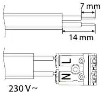
text_image
7 mm 14 mm 230 V~ N-
Strip the end of the power cable as shown and connect it to the terminal block (6). Blue wire to N and phase wire to L. The light fitting is protection class II □ and does not require a safety connection to electrical earth.
-
Make sure that the gasket (2) is fitted correctly and the cables don't get crushed between the mounting plate and the light fitting.
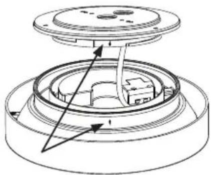
natural_image
Technical line drawing of a mechanical assembly with no visible text or symbols- Push the light fitting onto the mounting plate so that the markings (7) line up, then twist the light fitting anticlockwise until it locks into place.
Responsible disposal
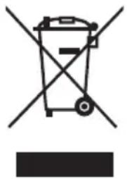
This symbol indicates that this product should not be disposed of with general household waste. This applies throughout the entire EU. In order to prevent any harm to the environment or health hazards caused by incorrect waste disposal, the product must be handed in for recycling so that the material can be disposed of in a responsible manner. When recycling your product, take it to your local collection facility or contact the place of purchase. They will ensure that the product is disposed of in an environmentally sound manner.
natural_image
Symbol of a trash bin crossed with no text or labels, representing environmental restriction (no text present)Specifications
36-6461 Silver, 36-6463 White
Bulb LED 10 W, The light bulb must only be replaced by a qualified electrician.
Diameter 22 cm
Luminous flux 800 lm
Weight 0.55 kg

36-6462 Silver, 36-6464 White
Bulb LED 15 W, The light bulb must only be replaced by a qualified electrician.
Diameter 30 cm
Luminous flux 1100 lm
Weight 0.82 kg

Input voltage 220–240 V, 50 Hz
Colour temperature 2700 K
IP rating IP54
Stepless brightness control/dimmable (only for standard or LED dimmers).
Plafond
Art.nr 36-6461 Modell H-CL-RI10W-S827-DI (Silver)
36-6463 H-CL-RI10W-W827-DI (Vit)
36-6462 H-CL-RI15W-S827-DI (Silver)
36-6464 H-CL-RI15W-W827-DI (Vit)
text_image
Technical diagram of a mechanical assembly with numbered components and exploded view indicatorsnatural_image
Technical line drawing of a mechanical assembly with circular components and a cable (no text or symbols)natural_image
Technical line drawing of a mechanical assembly with no visible text or symbolsnatural_image
Technical diagram of a mechanical assembly with gears and shafts, showing internal components and motion indicators (no text or labels)natural_image
Technical line drawing of a mechanical assembly with no visible text or symbolsnatural_image
Technical line drawing of a mechanical assembly with no visible text or symbolsnatural_image
Symbol of a trash bin crossed with no text or labels, representing environmental protection (no text present)Specifikationer
36-6461 Silver, 36-6463 Vit
text_image
Technical diagram of a mechanical assembly with numbered components and exploded view, likely for assembly or maintenance instructions.- Plafond
- Pakning
- Feste
- Tetningsplugger
- Merking for skruehull ved montering i takboks
- Plint for innkommende kabel
- Merkinger for montering av plafond på feste
- Ekstra skrue til takboks (2 ×)
- Pakning til montering på takboks (2 ×)
- Selvheftende teip til distansehylsene på festet (3 ×)
- Distansehylse (3 stk.)
- Skrue, stålskive, myk skive og plugg (3 ×)
Installasjon
text_image
! ON OFF ✓-
Festet er beregnet for montering på takboks. Mål avstanden mellom takboksens skruer og bore hull i festet med den samme avstanden. I festet er det merket (5) for hulltaking for de vanligste takboksene. Lag hull til skruen i pakningen (9).
-
Trekk innkommende kabel gjennom en tetningsplugg (4). Monter pakningen (2) på plafonden (1).
natural_image
Technical line drawing of a mechanical assembly with circular components and a coiled cable (no text or symbols)natural_image
Technical line drawing of a mechanical assembly with concentric rings and directional arrows (no text or symbols)B) Montering i tak eller på vegg
natural_image
Technical diagram of a mechanical assembly with gears and shafts, showing internal components and motion indicators (no text or labels)natural_image
Technical line drawing of a mechanical assembly with no visible text or symbols- Trykk plafonden mot festet sånn at markeringene (7) er rett ovenfor hverandre, og drei plafonden moturs så den låses fast.
C) Montering mot tak/vegg med utenpåliggende kabel
text_image
! ON OFF ✓natural_image
Technical line drawing of a mechanical assembly with no visible text or symbols- Trykk plafonden mot festet sånn at markeringene (7) er rett ovenfor hverandre, og drei plafonden moturs så den låses fast.
Avfallshåndtering
natural_image
Symbol of a trash bin crossed with no text or labels, representing environmental protection (no text present)Spesifikasjoner
text_image
Technical diagram of a mechanical assembly with numbered components and exploded view, likely for assembly or maintenance instructions.natural_image
Technical line drawing of a mechanical assembly with circular components and a central component (no text or symbols)natural_image
Technical line drawing of a mechanical assembly with no visible text or symbolsnatural_image
Technical diagram of a mechanical assembly with gears and shafts, showing internal components and motion indicators (no text or labels)natural_image
Technical line drawing of a mechanical assembly with no visible text or symbolsnatural_image
Technical line drawing of a mechanical assembly with no visible text or symbolsnatural_image
Symbol of a trash bin crossed with no text or labels, accompanied by a black rectangular block below (no text or symbols present)Tekniset tiedot
text_image
Technical diagram of a mechanical assembly with numbered components and exploded view indicatorstext_image
! ON OFF ✓natural_image
Technical line drawing of a mechanical assembly with no visible text or symbols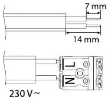
text_image
7 mm 14 mm 230 V ~natural_image
Technical line drawing of a mechanical assembly with no visible text or symbolsnatural_image
Technical line drawing of a mechanical assembly with no visible text or symbolsnatural_image
Technical line drawing of a mechanical assembly with no visible text or symbolsnatural_image
Symbol of a trash bin crossed with no text or labels, accompanied by a black rectangular block below (no text or symbols present)Technische Daten
POSTAL 10 - 13 Market Place
Kingston Upon Thames
Surrey
KT1 1JZ
DEUTSCHLAND
KUNDENSERVICE Unsere Homepage www.clasohlson.de