
Cable - Underfloor heating Magnum - Free user manual and instructions
Find the device manual for free Cable Magnum in PDF.


| Product Type | Underfloor Heating Cable |
| Brand | Magnum |
| Model | Cable |
| Power Supply | 230 V ~ 50/60 Hz |
| Maximum Thermostat Load | 16 A |
| Power Ratings Available | 300 W, 500 W, 700 W, 1000 W, 1250 W, 1700 W, 2100 W, 2600 W, 2900 W, 3300 W |
| Cable Lengths Available | 17 m (300 W) – 194 m (3300 W) |
| Resistance per Model | 300 W: 177 Ω, 500 W: 109 Ω, 700 W: 76 Ω, 1000 W: 53 Ω, 1250 W: 42 Ω, 1700 W: 31 Ω, 2100 W: 25 Ω, 2600 W: 20 Ω, 2900 W: 18 Ω, 3300 W: 16 Ω |
| Heating Application | Auxiliary or Primary heating |
| Compatible Floor Finishes | Tile, Marble, Slate, Wood, Laminate, Vinyl, Carpet (max tog 2.5) |
| Installation Surface | Foil finished insulation or existing concrete base |
| Wet Room Suitability | Yes (watertight, insulated) |
| Sensor Type | Floor sensor with flexible conduit |
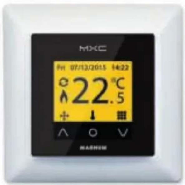
| Thermostat Included | Magnum X-treme Control digital thermostat (may be separate in some countries) |
| Shortening of Heating Cable | Not allowed |
| Shortening of Connecting Wire | Allowed (min. 0.5 m left) |
| Resistance Check Required | Before and after installation (record on inspection card) |
| Guarantee | Subject to correct installation; conditions at www.magnumheating.com |
| Programming/Use | Refer to thermostat manual for slow start-up after drying time |
Frequently Asked Questions - Cable Magnum
User questions about Cable Magnum
0 question about this device. Answer the ones you know or ask your own.
Ask a new question about this device
Download the instructions for your Underfloor heating in PDF format for free! Find your manual Cable - Magnum and take your electronic device back in hand. On this page are published all the documents necessary for the use of your device. Cable by Magnum.
USER MANUAL Cable Magnum
natural_image
Woman sitting on a white wall in an empty room with a window and tree branches visible (no text or symbols)MAGNUM Cable
Installatievoorschriften | Installation manual | Installationsanleitung
MAGNUM Cable
Geachte relatie,
natural_image
Yellow coiled cable with a black cable attached, no visible text or symbols2. Meetgegevens
| Type | Amp. Ohm | Lengte |
| 300 Watt | 1,3 177 17 m | |
| 500 Watt | 2,1 109 30 m | |
| 700 Watt | 3,0 76 42 m | |
| 1000 Watt | 4,3 53 59 m | |
| 1250 Watt | 5,4 42 73 m | |
| 1700 Watt | 7,4 31 100 m | |
| 2100 Watt | 9,1 25 124 m | |
| 2600 Watt | 11,3 20 153 m | |
| 2900 Watt | 12,8 18 171 m | |
| 3300 Watt | 14,3 16 194 m |
natural_image
Yellow flexible hose with digital multimeter and red circuit lines, placed on a plain surface (no text or symbols visible)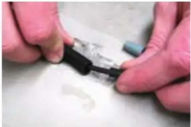
natural_image
Close-up of hands holding a small black connector with white plastic film, no visible text or symbols
natural_image
Close-up of a vertical metallic rod against a plain background (no text or symbols visible)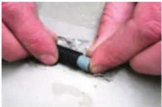
natural_image
Close-up of hands holding a small cylindrical object with a blue tip, resting on a surface (no visible text or symbols)MAGNUM Cable
natural_image
Close-up of a hand holding an electrical socket with exposed wires (no text or symbols visible)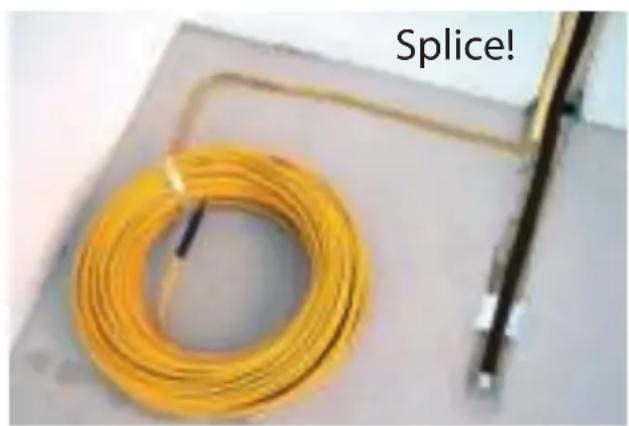
natural_image
Floor with curved wooden flooring and a vertical black line, no text or symbols visible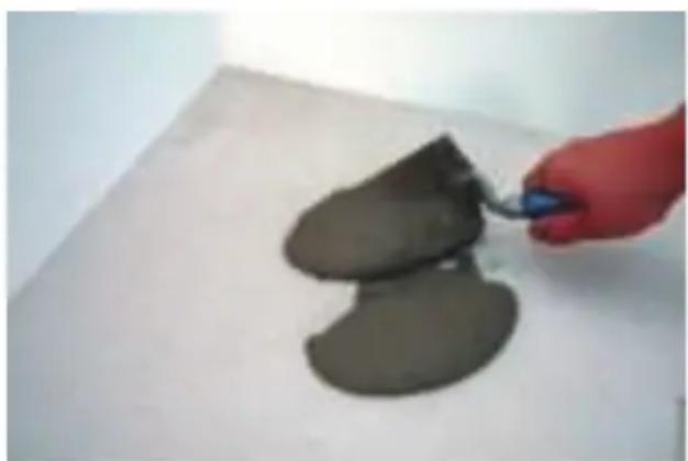
natural_image
Hand holding a blue tool next to two dark, irregularly shaped gray objects on a white surface (no text or symbols visible)MAGNUM Cable
natural_image
Close-up of a tiled floor with curved metal strips and a black tool inserted (no text or symbols visible)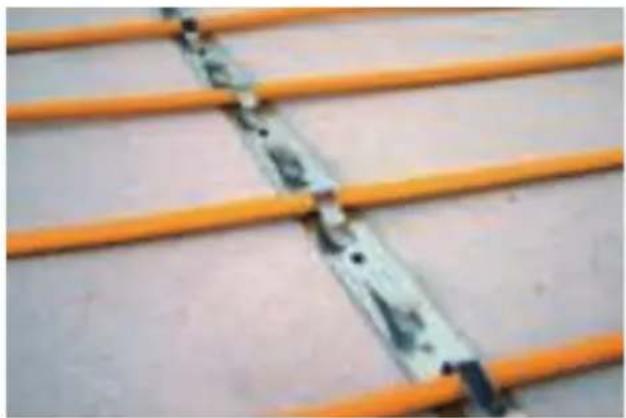
natural_image
Close-up of orange LED strip connectors with metallic contacts and connectors (no text or symbols visible)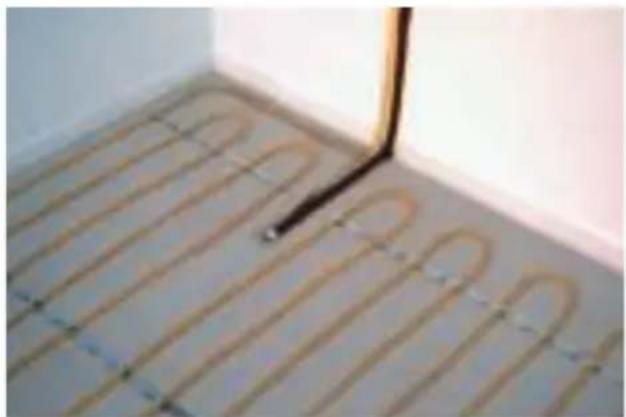
natural_image
Interior view of a room with curved wooden flooring and a black vertical line, no text or symbols visibleMAGNUM Cable
natural_image
Industrial metal shelving unit with yellow grilles and a cloth-covered wall (no visible text or symbols)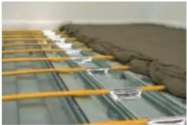
natural_image
Industrial floor with yellow metal grating and gray material, no visible text or symbols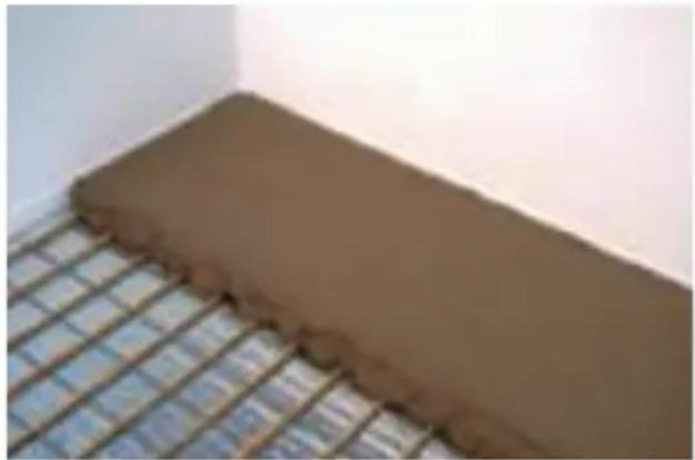
natural_image
Close-up of a brown cylindrical object placed on a grid-patterned surface, no visible text or symbols.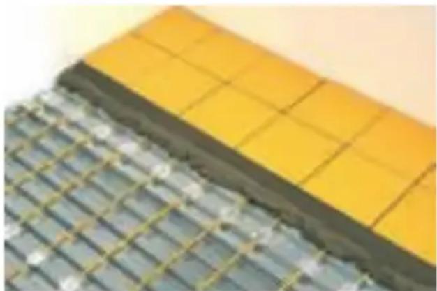
natural_image
Close-up of a tiled metal panel with yellow and gray panels, no visible text or symbolsMAGNUM Cable
Congratulations on the purchase of this MAGNUM product. This MAGNUM Heating product is manufactured from high quality, durable materials. To guarantee that your product functions optimally there are a few points of attention which are described in the Installation Instructions. We can only offer you the full guarantee if the system is correctly installed in accordance with these Installation Instructions. Carefully read the instructions prior to installation, do not forget the yellow centre page when doing so, and ensure that you have the correct tools and materials. The electrical installation must be carried out by a qualified electrician in accordance with IEE Regulations. Please visit www.magnumheating.com to find your local supplier if you have any questions, require more information or support.
© C&F Technics B.V. 2014 / All rights reserved
1. Check
Check the contents of the box before starting. A complete set consists of:
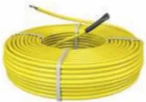
- A heating cable with connecting wire
- A MAGNUM X-treme Control digital thermostat incl. floorsensor*
- A flexible sensor tube
- Roll of Alutape*
- Installation instructions
*To be ordered as separate item in some countries. Please visit www.magnumheating.com for details.
natural_image
Yellow coiled cable with black cable and wire, no visible text or symbols
natural_image
Woman sitting on a white wall in a modern room with a window and tree branches visible (no text or symbols)2. Measurements
Type/Wattage Amp. Ohm Length
300 Watt 1,3 177 17m
500 Watt 2,1 109 30m
700 Watt 3,0 76 42m
1000 Watt 4,3 53 59m
1250 Watt 5,4 42 73m
1700 Watt 7,4 31 100m
2100 Watt 9,1 25 124m
2600 Watt 11,3 20 153m
2900 Watt 12,8 18 171m
3300 Watt 14,3 16 194m
3. Points of attention
The MAGNUM Cable is insulated and watertight and can be installed on Foil finished insulation (Kingspan or Celotex) or existing concrete bases. The construction of the cable also allows installation in wet spaces. The heating cable may never be
MAGNUM Cable
installed under fixed objects like wall units, kitchen units, baths, or showers and must be able to give off its warmth unimpeded.
The power supply must be disconnected during installation. All installations must be wired through a suitably rated MCB or RCCD when applicable. All installations in wet areas must be wired through a dedicated RCCD in line with the thermostat. All connections must be made by an approved Electrician in accordance with current IEE regulations. The electrical heating cable is patented worldwide and fully conforms to the European IEC 800 standards.
The connector cable can be extended or shortened, there must always be at least 0.5 meter of connecting wire left. The heating cable cannot be shortened! The end seal cannot be broken.
If multiple cables are installed in a space, they must be wired in parallel and a suitably rated junction box may be incorporated so that only one power cable runs to the thermostat. Maximum capacity of the thermostat is 16 Amperes. If fitting more than one cable set and the combined area length exceeds 194 meters (3400 watts), a suitably rated Contactor will have to be fitted. The thermostat may only be installed by a qualified electrician.
Before installing the MAGNUM Cable, the resistance reading should be taken and noted down on the inspection card in the center of this manual. Keep this inspection card in the meter cupboard in a visible place this is part of your guarantee! (see point 8)
The sensor must always remain IN the sensor conduit. Fit cap to end of the sensor conduit. If the sensor ever needs to be replaced it can then easily be removed.
The MAGNUM Cable can be used under various floor finishes - Tile, Marble, Slate, Wood, Laminate, Vinyl and Carpet. (Tog rate of
carpet and underlay should not exceed 2.5). If using underneath a wooden floor or carpet please contact your flooring supplier.
4. Guarantee
Please visit www.magnumheating.com for your local guarantee conditions.
5. Necessary materials
Required for installation:
- Standard junction box (min 35mm deep, preferably 50mm) for the thermostat.
- Mounting material: Tie wraps, alu-tape, MAGNUM Spacerstrips or smooth Weld Mesh.
- Electrical conduit for the connecting cable for the thermostat.
- Flexible mortar or sand/cement screed (dependent on the mounting height).
6. Preparation
- Check that the cable length/wattage is correct for the area of free floor surface that must be heated.
- Check the available electrical connection and mains voltage in the space for installation.
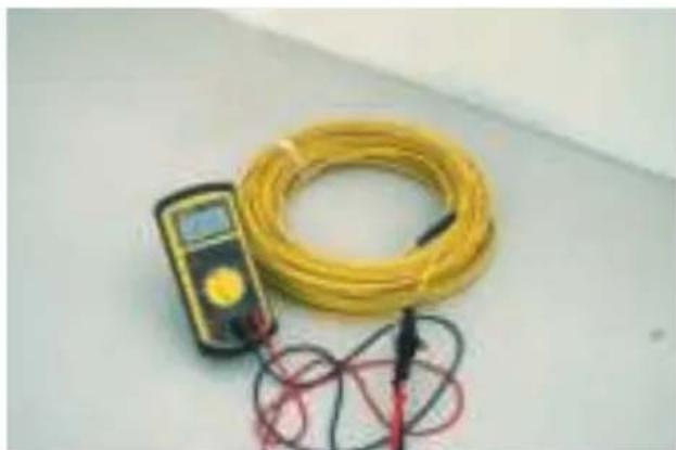
- Test the cable with a multimeter and check with the test data in Section 2.
- 1 or 2 grooves must be cut/ground in the wall for electrical conduits, 1 for the power cable and 1 for the floor sensor. Do NOT run the power cable and sensor cable through the same pipe.
- Ensure that the base floor is clean and level.
- Always apply insulation to the base floor if possible. Uninsulated floors will have downward heatloss.
- Place expansion strips around the perimeter of the area (for coping with the contraction and expansion of the floor).
MAGNUM Cable
7. Sensor
Ensure that the sensor is installed well clear (min. 50 cm) of central heating pipes, water pipes, drains and electrical wiring. The sensor must be installed in the middle of a cable loop for optimal temperature registration. Ensure that the heating cables do not make direct contact with the conduit in which the floor sensor is mounted.
8. Resistance readings
Before installing the Comfort Cable, the resistance reading should be taken and noted down on the inspection card in the center of this manual. The reading should be taken during the installation and on final completion. These readings should be as per the technical information (Point 2). Take measurements both between the resistance wires and between the resistance wire and the earth cladding. Keep this inspection card in the meter cupboard in a visible place! This forms part of your guarantee.
9. Calculations for Heat Requirements
150+ Watts/m² for prime heating of normal rooms cable spacing 100 mm
100/125 Watt sq. m for comfort heating of normal rooms cable spacing 125/150 mm
Example: for a conservatory of 20 sq. m floor surface multiply the total floor surface with the above mentioned capacities (20 x 150 Watt = 3000 Watt) Choose set 3300 - 3300 watt. Cable can be sized (or checked) by measuring the linear length i.e. Heat required 150 watts/m². Room size 4mx3m =12m² Cable spacing = 100mm. Therefore 4mx30 = 120 linear mts. Use 2100 Watt set (124 linear mts).
If there is any excess cable left after installation, you can space a few runs at
natural_image
Yellow measuring tape and multimeter on white surface, coiled with red wire (no text or symbols visible)
natural_image
Close-up of hands assembling a black and white electronic component (no visible text or symbols)
natural_image
Close-up of a vertical metallic rod against a plain background (no text or symbols visible)
natural_image
Close-up of hands holding a black plastic component with blue tip, partially covered by white paper (no text or symbols visible)MAGNUM Cable
50mm at the window & door areas of the room to lose it in the floor.
NEVER SHORTERN THE CABLE.
10. Fitting the cable to the floor
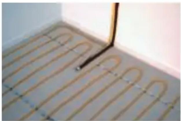
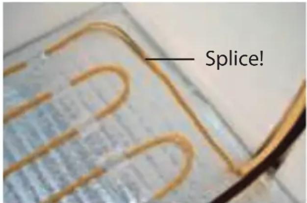
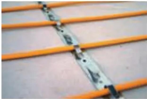
Feed the cable end (marked with *****) through the electrical pipe to the back box for the thermostat. The word "splice" must stay visible. Splice must be covered by screed. Fix the spacer strips at 500 - 600 mm centres with masonry or Hilti nails. Attach the cable in a zigzag fashion with a distance between the cable as required. If reinforcing is used (Smooth Weld mesh at 100mm square) plastic tie wraps can be used for attaching the cable directly to the reinforcing. Extend the 2nd electrical pipe to about 50 cm from the wall and have it end in the middle of a cable loop. Pull the sensor cable to the back box and ensure that the sensor is in the conduit. Ensure the cap is placed on the end of the conduit so that replacing the sensor is always possible. Please contact your local Technical Department www.magnumheating.com if you require assistance on the spacing of the cable.
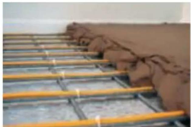
11A. Applying the mortar directly to a concrete subfloor
-
Lay the spacer strips at 500 -600mm centres. Attach the cable at the desired/ specified spacing.
-
Ensure a good bond and by brushing the subfloor with cement powder or PVC glue.
-
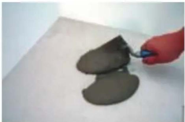
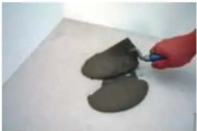
Then apply a thin layer of sand/cement screed (5/6:1) of 3.5 to 5.0 cm. Allow it to cure before the tiles can be laid or other types of floor coverings applied.
-
This method of application is also suitable for applying pourable liquid screeds in
natural_image
Close-up of a blue electrical socket with exposed wires and colored insulation (no text or symbols visible)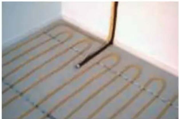
natural_image
Interior view of a room with curved wooden flooring and a black line extending upward (no text or symbols visible)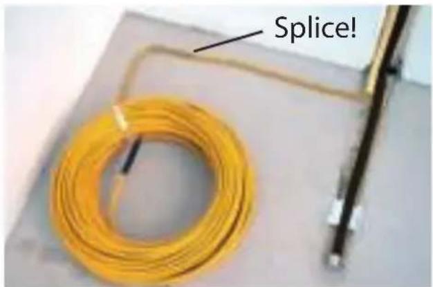
natural_image
Hand holding a blue tool applying dark, irregularly shaped clay or dough on a white surface (no text or symbols visible)LEES GOED DOOR A.U.B.: PLEASE READ CAREFULLY: BITTE SORGFÄLTIG LESEN:
BELANGRIJKE AANDACHTSPUNTEN UIT DE ALGEMENE INSTALLATIEVOORSCHRIFTEN
VOORKOM BESCHADIGING
AUXILIARY OR PRIMARY HEATING The MAGNUM Mat/Cable is designed to function as
IMPORTANT POINTS OF ATTENTION FROM THE GENERAL INSTALLATION INSTRUCTIONS
PREVENT DAMAGING
Ensure that the surface where the heating cable is worked on is flat, clean, and free of dust and grease. Prevent the use of sharp tools, walking over the heating cables and allways ensure to work carefully.
ENSURE THE MAT IS COMPLETELY INSTALLED
under fixed objects like wall units, kitchen units,
baths, or showers and must be able to give off its
warmth unimpeded. The MAGNUM Mat/Cable may
only be incorporated into the free floor areas.
MCB OR RCCD REQUIRED
All installations must be wired through a suitably rated MCB or RCCD when applicable.
NEVER CUT THE HEATING CABLE! AND NEVER
The heating cable CANNOT be cut. Please check
your local supplier via magnumheating.com if the
cable is damaged.
de support line: tel. 0900-9110911
Ensure that the sensor is installed well clear (min.
50 cm) of central heating pipes, water pipes, drains
and electrical wiring. Install the sensor as closely as
possible in the middle of 2 loops. Ensure that the
heating cables do not make direct contact with
the conduit in which the floor sensor is mounted.
The Ground Truth image displays a single, solid horizontal line. According to Rule 2 (UNDERSCORE & LINE RULES), this is a stylistic or background line, not a placeholder underscore. Therefore, the OCR result must ignore it and output nothing or only meaningful text. The provided OCR content is "____", which consists of four underscores. This is an incorrect interpretation of the line as a placeholder, violating the rule that stylistic lines must be ignored. The OCR has hallucinated underscores where none should exist based on the GT's visual context. Hence, the OCR result is inconsistent with the Ground Truth.
AUXILIARY OR PRIMARY HEATING
Floor Heating installed in:
Resistance readings:
A: Between centre core wires
(within 10% margin!)
B: Between centre core wire #1 and the earth
(This should read "0")
C: Between centre core wire #2 and the earth
(This should read "0")
Initial Reading:
A:......Ohm
B:......Ohm
C:......Ohm
Mat/Cable Laid:
A:......Ohm
B:......Ohm
C:......Ohm
LET OP!
ONDER DE VLOER IS EEN 230 VOLT VLOERVERWARMINGSSYSTEEM GEINSTALLEERD! NOOIT BOREN OF SCHROEVEN IN DE VLOER!
ZIE TEKENING/FOTO VOOR DE POSITIE VAN DE VLOERVERWARMING.
□ MAGNUM Mat
□ MAGNUM Cable
an auxiliary heating source, however, by installing more capacity than it is no longer necessary to install a separate radiator and the MAGNUM Mat/ Cable can serve as the main source of heating. This allows more space for fixtures or furniture. The capacity must match the heating requirements / calculations for the space in question. Please check your local supplier via magnumheating.com for advice.
ALLOW THE FLOOR SUFFICIENT DRYING TIME: Consult the supplier/manufacturer regarding the applicable drying time for the product. For sand/cement screed floors a drying time of 1 week per applied cm with a minimum of 30 days is generally observed. Consult the supplier/manufacturer regarding the applicable drying time for your situation.
The position of the thermostat is determined in accordance with current local regulations USE OF THE THERMOSTAT Check the thermostats manual for correct programming.
SHORTENING/EXTENDING THE CONNECTING CABLE: The connector cable can be extended or shortened, there must always be at least 0.5 meter of connecting wire left. The heating cable cannot be shortened; the end seal cannot be broken. THEMOSTAT POSITION:
thicknesses of between 3 and at most 6 cm. 5. Protect the cables when bringing in the cement or grout by using duckboards. Never use wheelbarrows with unprotected footrests.
NB: For large spaces it is necessary to create or observe expansion joints in multiples of approx. 40/50 m2. The cables may not cross the expansion joints to avoid damaging the cables.
11B: Applied Directly on top of Insulation
When laying the Comfort cable onto the insulation the Comfort cable must be laid and secured onto a steel mesh. Do not install the cable directly onto the insulation. The cable is laid on to a smooth reinforcing mesh (approximately 100mm square), and secured with tie wraps. When using insulation, the top surface of the insulation must be aluminium covered and coated appropriately to resist reaction with screed. Kingspan and Celotex manufacture insulation boards for the sole purpose of underfloor heating. The Comfort cable must not come into contact with the insulation. Contact the insulation manufacturer for compatibility with cable floor heating systems and fitting instructions.
It is very important that the bedding is applied free of air bubbles. Air bubbles form insulating, non-conductive areas where the cable cannot release its heat and a danger of overheating arises which can cause damage to the cable.
To avoid this first of all wetter screed must initially be used to enclose the cable in the screed. Following this drier cement can be used for levelling the final bedding. In this case a pourable liquid screed is also a good option.
Protect the cables when bringing in the cement or grout by using duckboards. Never use wheelbarrows with unprotected footrests.
natural_image
Close-up of orange plastic strips with black connectors, no visible text or symbols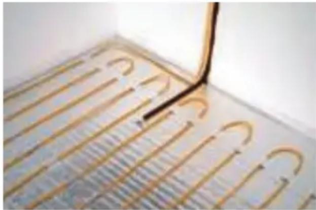
natural_image
Close-up of a metallic grid pattern with curved and straight lines, no visible text or symbols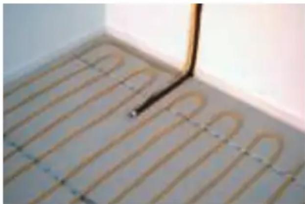
natural_image
Interior corner of a room with curved wooden flooring and a vertical black line, no visible text or symbolsMAGNUM Cable
Remember to take the resistance readings throughout this installation process and mark opposite.
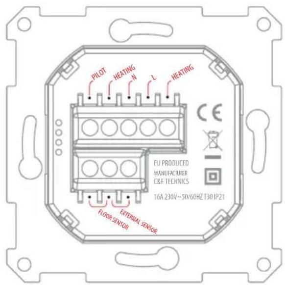
12. Connecting the thermostat:
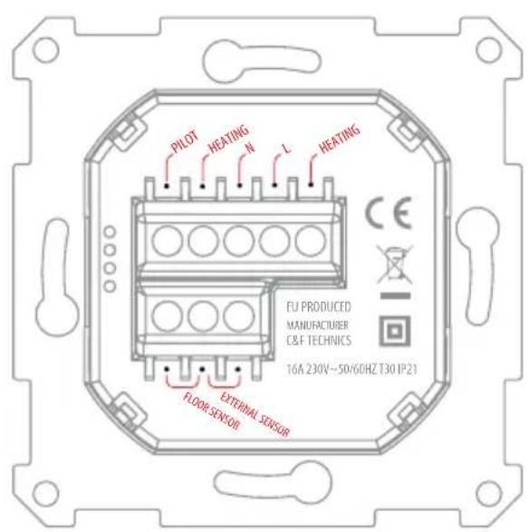
Installation needs to be done by a qualified electrician in accordance with all current wiring and building regulations. Before installation or re-installation of the thermostat always isolate the power to the thermostat.
Check if the power is off. Remove the display frame by pushing a non sharp instrument (for example the point of a ballpoint pen) carefully in the square whole underneath the thermostat. The display frame and the cover frame can be removed.
| PILOT | : Pilot Wire (Domotica) |
| HEATING (N) | : Heating Cable connection (N) |
| N | : Power connection (Neutral) |
| L | : Power connection (Live) |
| HEATING (L) | : Heating Cable connection (L) |
| FLOOR SENSOR: Floor sensor connections | |
| EXT. SENSOR | : External sensor connections |
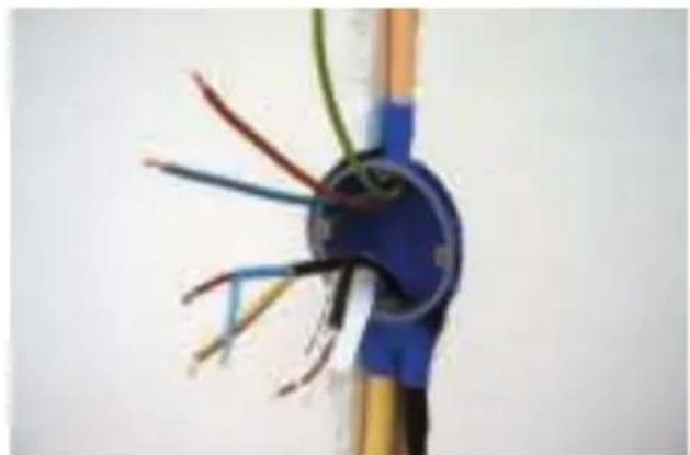
EARTHING: We advice to make an external earth wire connection from the thermostat with the supplied terminal block.
Position the thermostat and install onto the back box (not supplied). Place the display frame back into position by pushing it softly.
To install and set up the thermostat, please use the manual that is included with the thermostat.
13. Using the system for the first time
Depending on the drying time specified for the Flexible adhesive or self-levelling compound, however not sooner than 21 days after installation due to the natural
natural_image
Industrial metal structure with yellow supports and a large brown sculpture on top (no visible text or symbols)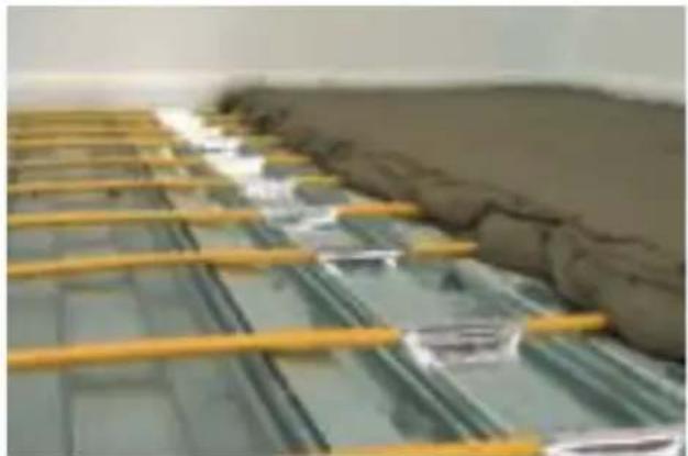
natural_image
Interior view of a tiled room with yellow metal grating and gray wall (no visible text or symbols)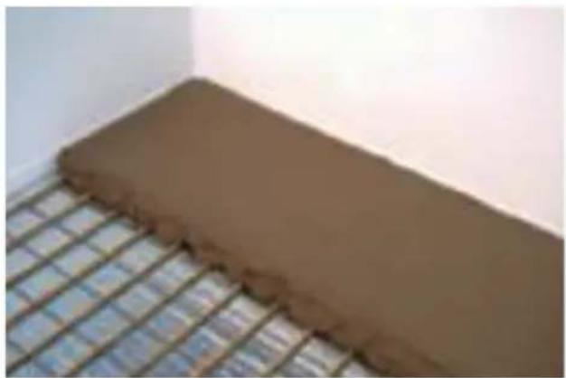
natural_image
Close-up of a brown rectangular object placed on a grid-patterned surface, no visible text or symbols.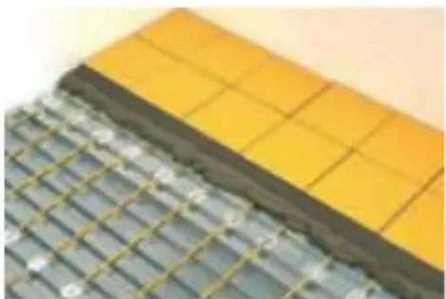
natural_image
Close-up of a yellow tiled wall and a grid-patterned surface (no text or symbols visible)MAGNUM Cable
expulsion of moisture from the floor. Turning on the system sooner can damage the floor. Please use the "Slow start-up" mode on your thermostat.

MAGNUM Cable
natural_image
Yellow coiled hose with black cable, no visible text or symbols
natural_image
Woman sitting on a wall in a minimalist room with window and tree branches visible (no text or symbols)2. Messdaten
| Typ | Amp. | Ohm | Länge | ||
| 300 Watt | 1,3 | 177 | 17 m | ||
| 500 Watt | 2,1 | 109 | 30 m | ||
| 700 Watt | 3,0 | 76 | 42 m | ||
| 1000 Watt | 4,3 | 53 | 59 m | ||
| 1250 Watt | 5,4 | 42 | 73 m | ||
| 1700 Watt | 7,4 | 31 | 100 m | ||
| 2100 Watt | 9,1 | 25 | 124 m | ||
| 2600 Watt | 11,3 | 20 | 153 m | ||
| 2900 Watt | 12,8 | 18 | 171 m | ||
| 3300 Watt | 14,3 | 16 | 194 m |
natural_image
Yellow flexible hose with digital multimeter and red coil, placed on a plain surface (no text or symbols visible)
natural_image
Close-up of hands assembling a small electronic component (no visible text or symbols)
natural_image
Close-up of a vertical metallic rod against a plain background (no text or symbols visible)
natural_image
Close-up of hands holding a small black and blue plastic object with a white crack on a white surface (no text or symbols visible)MAGNUM Cable
natural_image
Close-up of a blue electrical socket with exposed wires and wires, no text or symbols visible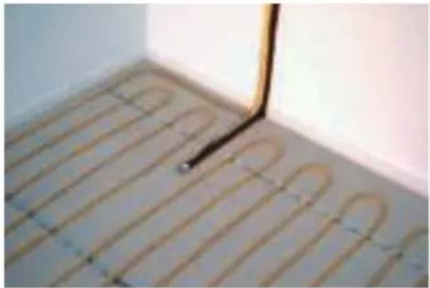
natural_image
Interior corner of a room with curved tiled floor and a black line extending upward (no text or symbols visible)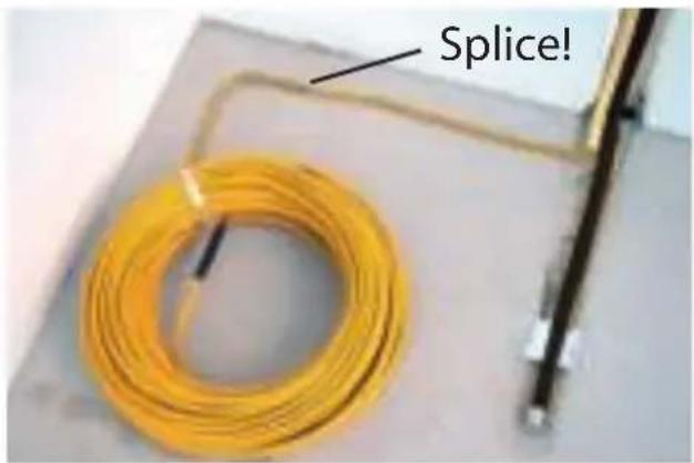
natural_image
Hand holding a small object over two dark, irregularly shaped objects on a white surface (no text or symbols visible)MAGNUM Cable
natural_image
Close-up of orange plastic strips with metallic components embedded in a wall (no text or symbols visible)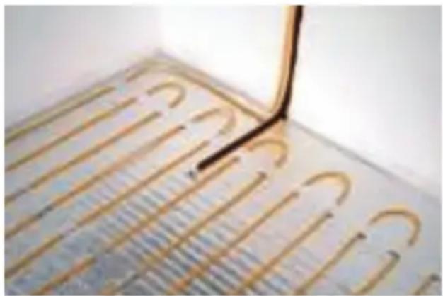
natural_image
Close-up of a metallic heating element grid with curved copper traces, no visible text or symbols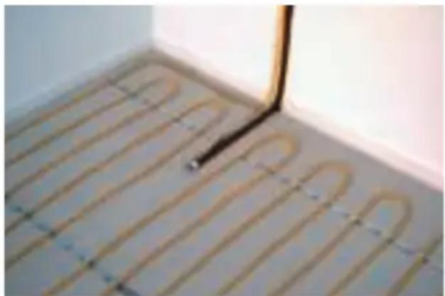
natural_image
Interior corner of a room with curved tiled floor and a vertical black line, no visible text or symbolsMAGNUM Cable
natural_image
Industrial metal structure with yellow supports and a cloth-covered wall (no visible text or symbols)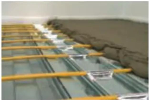
natural_image
Close-up of yellow metal grating with green glass panels and a gray wall, no visible text or symbols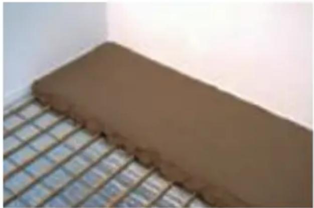
natural_image
Close-up of a brown cylindrical object placed on a grid-patterned surface, no visible text or symbols.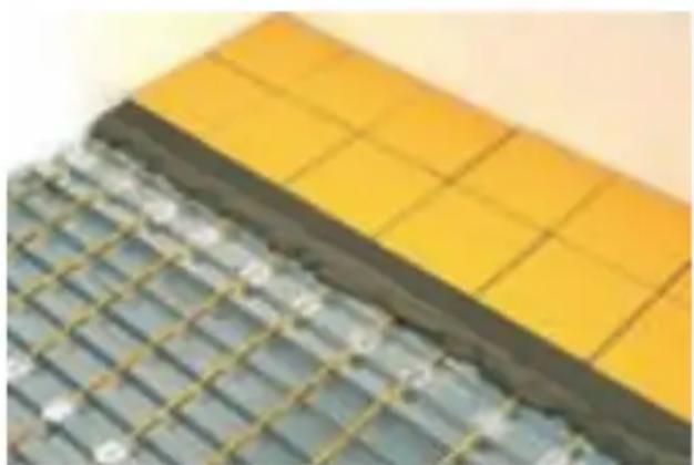
natural_image
Close-up of a tiled wall with yellow and gray panels, no visible text or symbolsMAGNUM Cable

MAGNUM HEATING
Comfort | Safety | Control
C&F Technics
T +31(0)166-609 300
MAGNUM Heating B.V.
F +31(0)166-604 877
Slabbecoornweg 41a
E info@magnumheating.nl
4691RZ Tholen
W magnumheating.nl

- MAGNUM Cable
- Meetgegevens
- Check
- Measurements
- Points of attention
- Guarantee
- Necessary materials
- Preparation
- Sensor
- Resistance readings
- Calculations for Heat Requirements
- Fitting the cable to the floor
- 11A. Applying the mortar directly to a concrete subfloor
- LEES GOED DOOR A.U.B.: PLEASE READ CAREFULLY: BITTE SORGFÄLTIG LESEN:
- LET OP!
- 11B: Applied Directly on top of Insulation
- Connecting the thermostat:
- Using the system for the first time
- Messdaten
- MAGNUM HEATING
Brand : Magnum
Model : Cable
Category : Underfloor heating