
RAD-010 - Radio Steren - Free user manual and instructions
Find the device manual for free RAD-010 Steren in PDF.


| Product Type | Two-way radio (walkie-talkie) kit |
| Brand | Steren |
| Model | RAD-010 |
| Dimensions | 59 x 34 x 114 mm per unit |
| Weight | 250 g per unit (including battery) |
| Power Supply | 3.6 V rechargeable Li-ion battery (1300 mAh) or charger base input: 120 V~7 W |
| Frequency Range | UHF 400 – 470 MHz |
| Number of Channels | 16 |
| Channel Spacing | 12.5 kHz |
| Operating Temperature | -20°C to +60°C |
| Transmission Power | ≤3 W |
| Modulation Mode | FM (F3E) |
| Receiver Sensitivity | <0.2 μV (at 12 dB SINAD) |
| Audio Output Power | 400 mW |
| Charger Base Output | 3.8 V at 500 mA |
| Battery Charging Time | 5 continuous hours for first charge |
| Range (under optimum conditions) | Up to 30 km |
| Special Functions | VOX (hands-free), scanning, programmable via PC software |
| In the Box | 2 radios, 2 charger bases, 2 clips, 4 screws, 1 programming cable |
| Safety Features | Lock button, battery removal, antenna replacement, caution against water and damage |
| Warranty | Refer to Steren website for details |
Frequently Asked Questions - RAD-010 Steren
User questions about RAD-010 Steren
0 question about this device. Answer the ones you know or ask your own.
Ask a new question about this device
Download the instructions for your Radio in PDF format for free! Find your manual RAD-010 - Steren and take your electronic device back in hand. On this page are published all the documents necessary for the use of your device. RAD-010 by Steren.
USER MANUAL RAD-010 Steren
natural_image
Two black walkiehens with four speakers, shown from side and top views (no text or symbols visible)KIT DE RADIOS
INTERCOMUNICADORES
RAD-010
IMPORTANTE
natural_image
Diagram showing a mechanical device with a rotating component and a walkie-talkie device, both without any text or symbols.BATERÍA
natural_image
Diagram of a mechanical component with three cylindrical parts mounted on a base (no text or symbols)AJUSTAR VOLUMEN
natural_image
Illustration of a hand pointing at an electronic device with three speakers (no text or symbols visible)natural_image
Diagram showing a walkie-talkie connected to a laptop via cable, with no text or symbols present.APÉNDICE
natural_image
Two black walkiehens with four speakers, shown from different angles (no text or symbols visible)2-WAY RADIOS
RAD-010
IMPORTANT
Read these manual to avoid any damage.
The instructions of these manual are for reference about the product.
There may be differences due to update.
Please check our web site www.steren.com to obtain the latest version of the instruction manual.
CAUTIONS
- This product is NOT a toy; keep it away from children.
- Do not try to open the device; It could be damage and void the warranty.
- Do not use if have been hit hard, dropped or otherwise damaged.
- Do not use or store the device in places where there are dripping, dampness, or water splashes; May cause malfunction or electric shock.
- Periodically check the battery. If it will not be used it for an extended period of time, remove it.
- Do not use the device if the antenna is damaged. If the skin has contact with the damaged antenna, it may cause slight burns.
- To avoid problems or damages caused by electromagnetic interference, turn off the radio in all places where there are notices to that effect (hospitals, aircraft, gas stations, etc.).
- This product is not intended for use by persons with different abilities, unless they are supervised or instructed by a person responsible for its safety.
- Before using the radio for the first time, charge battery at 100% .
The operation of this device is subject to the following two conditions: (1) it is possible that this device may not cause harmful interference and (2) this device must accept any interference, including interference that may cause undesired operation.
"This device is designed to operate with the antennas that are listed below and for a maximum antenna gain of 10 dBi. The use with this device of antennas not included in this list or that have a gain greater than 10 dBi are prohibited. The required impedance of the antenna is 50 ohms"
CONTENT
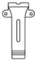 Clip (x2) Clip (x2) | 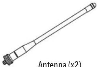 |
 Screws (x4) Screws (x4) | 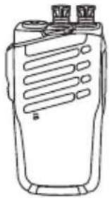 Radio (x2) Radio (x2) |
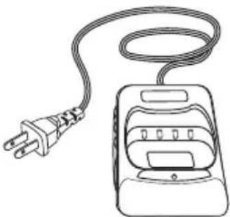 Charger base (x2) Charger base (x2) | 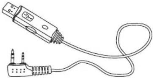 Programming cable (x1) Programming cable (x1) |
PARTS
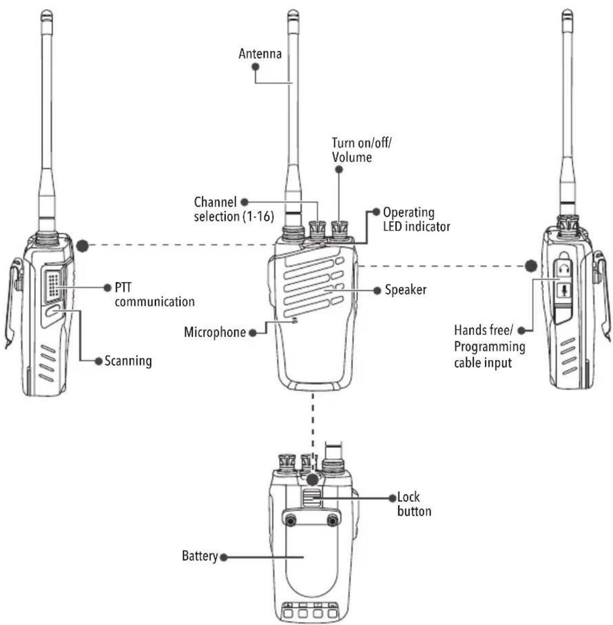
RADIO
CHARGER BASE
INSTALLATION
ANTENNA
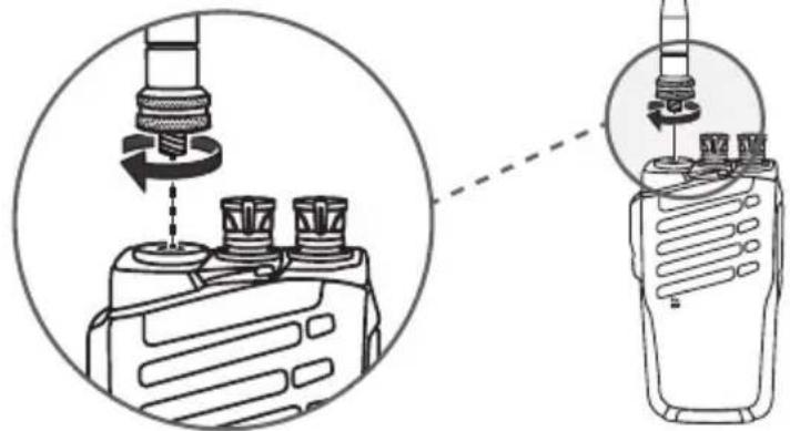
Insert the antenna into the connector that is located at top of the radio and rotate until will be fixed.
natural_image
Diagram showing a mechanical device with rotating components and a separate walkie-talkie device (no text or symbols present)BATTERY
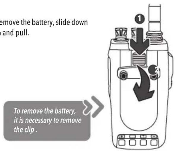
If you want to remove the battery, slide down the lock button and pull.
CLIP
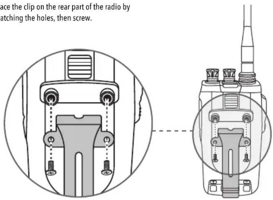
Place the clip on the rear part of the radio by matching the holes, then screw.
CHARGING BATTERY

Charge for 5 continuous hours.
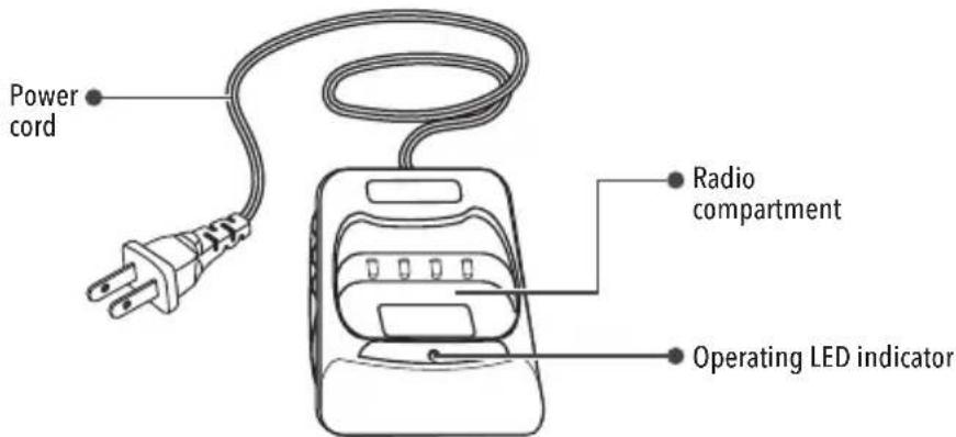
1 Connect the base to an electrical power outlet.
2 Make sure that the radio makes contact with the connectors. The LED will be indicate that the battery is charging.
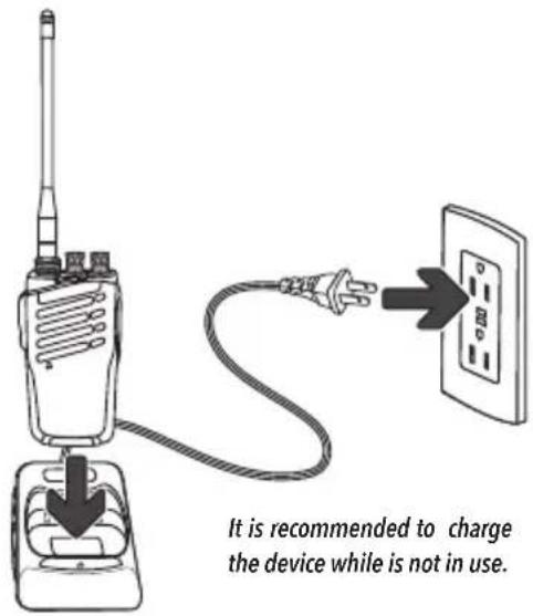
It is recommended to charge the device while is not in use.
BASIC OPERATION

To be able to establish the communication, turn on, adjust the volume and select the same channel in both radios.
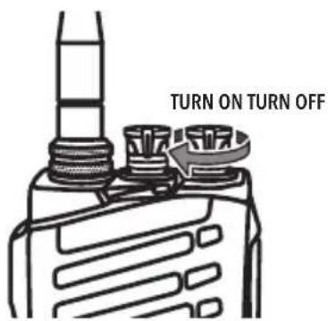
TURN ON/OFF
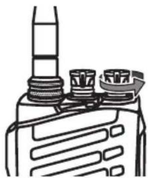
To turn on the device, rotate the turn on / off knob in clockwise direction until you can hear a tone. If you want to turn off the radio, rotate the knob counterclockwise until you hear a click.
natural_image
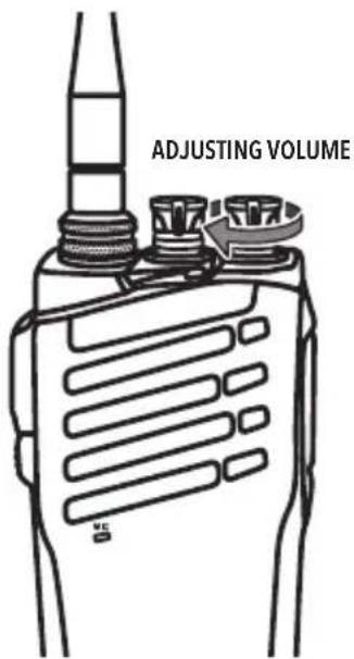
Diagram of a mechanical component with three cylindrical parts mounted on a base (no text or symbols)ADJUSTING VOLUME
Once the radio is turn on, adjust the volume level by moving the turn on / off knob clockwise.
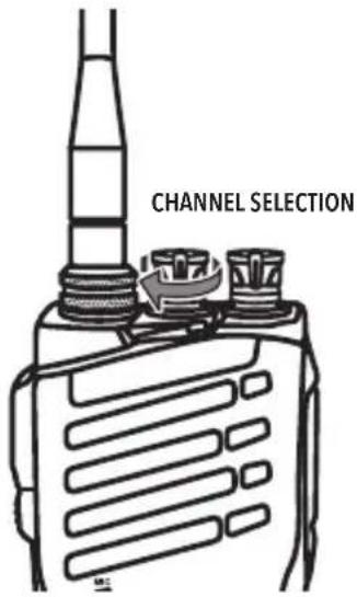
CHANNEL SELECTION
Turn the channel selection knob. The device will send a message of the selected channel.
TRANSMISSION AND RECEPTION CALLS
To transmit, press and hold the PTT button and speak in a normal voice tone. The operation LED will turn on red.
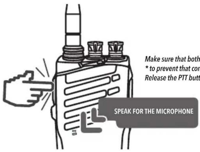
* Up to 30 km range under optimum conditions
Make sure that both radios are in range
* to prevent that communication being cut.
Release the PTT button to receive a ring signal
SCANNING
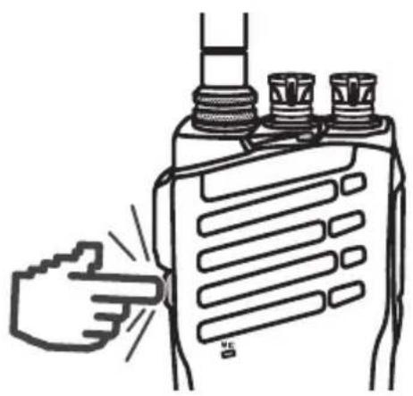
Press and hold the SCAN button to catch available transmissions in the area. The LED indicator will turn green
natural_image
Illustration of a hand pointing at a walkie-talkie device (no text or symbols visible)RAD-010 PROGRAMMING SOFTWARE
Enter to website: www.steren.com and search product RAD-010. Go to the Support and Help section, and select from the Programming Software option. Software downloading will automatically start. Unzip the file and locate the RAD-010 software folder.
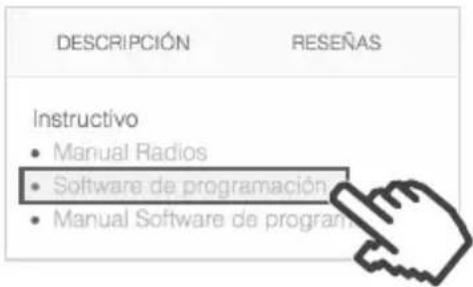
Use the software to configure additional functions.
DRIVERS INSTALLATION: WINDOWS 10
1 Locate the Vista3200 win 10 file in the Win 10 driver folder and run it.

SERSPL

SERSPL.VXD

SEFWPI

Vista3200_win10
11/12/2016 08:37 ... Informa
11/12/2016 08:37 ... Control
11/12/2016 08:37 ... Informa
11/12/2016 08:37 ... Aplicaci
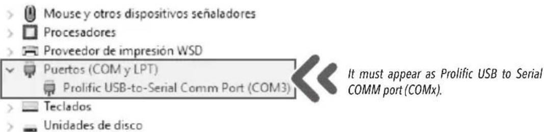
2 Follow the installation steps. Once this is complete, connect the radio to a USB port and open the Control Panel. To verify that the driver has been installed correctly, locate the Devices Manager and search the Ports (COM and LPT) option and select it.
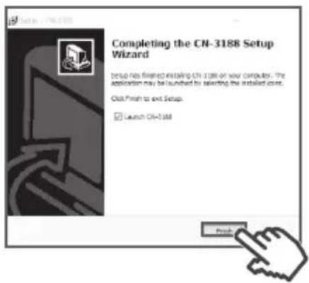
Select the file RAD-010 software.10 setup and follow the installation steps. On the last installation screen, uncheck "Launch CN-3188" and press Finish.
On the desktop you will find a direct access named CN-3188, click here, with the right mouse button and run it as Administrator.
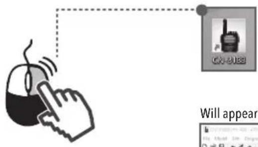
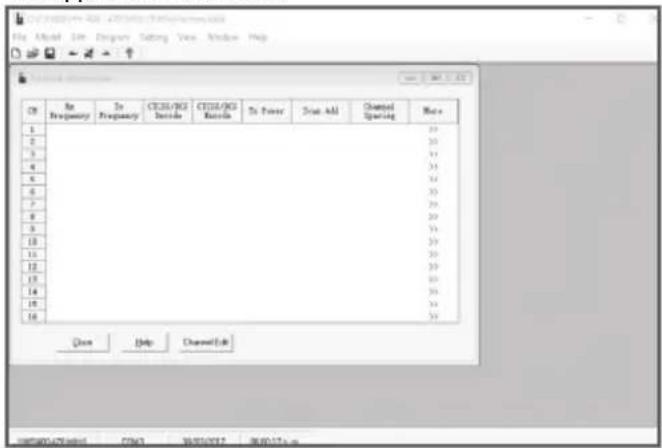
Will appear the next screen:
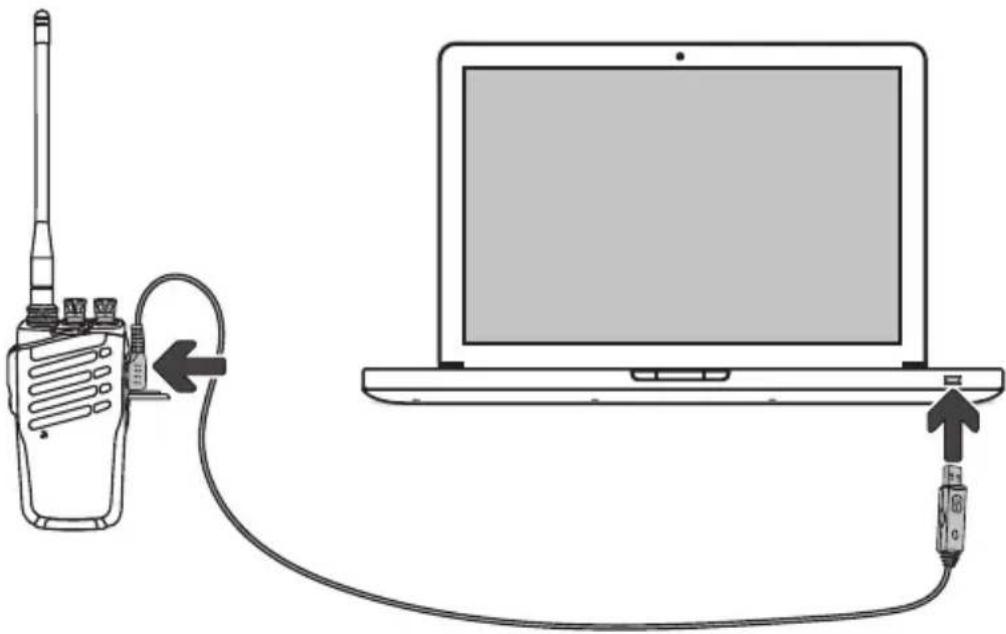
Connect the programming cable to the radio and to a USB port in the computer. Then turn on the radio.
natural_image
Diagram showing a walkie-talkie connected to a laptop via cable, with no text or symbols present.Return to the Devices Manager and identify the COM port where is connected to (COM3 port is shown in the example).
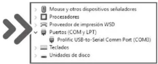
In the RAD-010 software, select the Setting, Set Com, and choose the port that you previously wrote (in the COM3 example).
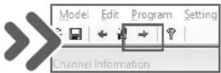
Press the left arrow to connect the radio and read the information.
![CN-3188[UHF: 400 - 470 MHz] [FileName:new.rdat] File Model Edit Program Setting View Window Channel Info CH Rx Frequency Tx Frequency CTCSS/DCS Decode CTCSS/DC Encode Read data from radio Complete:0% Password: Read Cancel](/content/2026/05/791081/images/47eaf21f23f9b869c647b0221f5ea4f1237c74bb1bc1a9bcab4edcec65dcbf3d.jpg)
If the connection is successful, the following screen will appear:
| CK | Rx Frequency | Tz Frequency | CTCSS/DCS Decode | CTCSS/DCS Encode | Tx Power | Scan Add | Channel Spacing | More |
| 1 | 436.02500 | 436.02500 | 82.5 | 82.5 | High | Add | 25R(Wide) | >> |
| 2 | 436.07500 | 436.07500 | 88.5 | 88.5 | High | Add | 25R(Wide) | >> |
| 3 | 436.12500 | 436.12500 | D032I | D032I | High | Add | 25R(Wide) | >> |
| 4 | 436.17500 | 436.17500 | 67.0 | 67.0 | High | Add | 25R(Wide) | >> |
| 5 | 436.22500 | 436.22500 | 118.8 | 118.8 | High | Add | 25R(Wide) | >> |
| 6 | 436.27500 | 436.27500 | D073H | D073H | High | Add | 25R(Wide) | >> |
| 7 | 448.97500 | 448.97500 | 74.4 | 74.4 | High | Add | 25R(Wide) | >> |
| 8 | 436.37500 | 436.37500 | D195H | D195H | High | Add | 25R(Wide) | >> |
| 9 | 436.42500 | 436.42500 | 131.8 | 131.8 | High | Add | 25R(Wide) | >> |
| 10 | 436.47500 | 436.47500 | D311H | D311H | High | Add | 25R(Wide) | >> |
| 11 | 436.52500 | 436.52500 | 107.2 | 107.2 | High | Add | 25R(Wide) | >> |
| 12 | 436.57500 | 436.57500 | 136.5 | 136.5 | High | Add | 25R(Wide) | >> |
| 13 | 436.62500 | 436.62500 | D053I | D053I | High | Add | 25R(Wide) | >> |
| 14 | 436.67500 | 436.67500 | D115I | D115I | High | Add | 25R(Wide) | >> |
| 15 | 436.72500 | 436.72500 | 77.0 | 77.0 | High | Add | 25R(Wide) | >> |
| 16 | 436.77500 | 436.77500 | 91.5 | 91.5 | High | Add | 25R(Wide) |
Modify the parameters that you require. Check the Appendix in the following page for further reference.
At the end, select the right arrow to save the changed values, turn off the radio and exit the program.
APPENDIX
• CH: Channel to be modified.
• RX Frequency: Receiving frequency.
• TX Frequency: Transmission frequency.
- CTCSS /DCS Dec: CTCSS / DCS decoder.
- CTCSS /DCS Enc: CTCSS / DCS encodifier. The radio can only communicate with radios having the same CTCSS / DCS settings.
• TX power: Transmission frequency power.
- Scan Add: Select whether or not the channel will appear in the searching function.
- Channel spacing: Separation between channels.
If you want to activate the VOX function, go to the Edit menu, Function Setup Submenu.
SPECIFICATIONS
Input: 3.6 V --- (rigid battery)
Frequency range: UHF 400 - 470 MHz
Channels: 16
Channel space: 12.5 kHz
Operating temperature range: -20 °C to +60 °C
Dimensions: 59 x 34 x 114 mm
Weight: 250 g
Transmitter: UHF
Transmission power: ≤3 W
Stabilization: ±2.5 ppm
Modulation mode: FM (F3E)
Spurious emissions: ≤-60 dB
FM noise: ≤-40 dB
Audio distortion: ≤5%
Adjacent channel power: ≥55 dB
Maximum frequency deviation: ≤±5 kHz
Receiver: UHF
Stabilization frequency: ±2.5 ppm
Sensitivity (at 12dB SINARD): <0.2 μV
FM receiver bandwidth: ≥±7 kHz
Adjacent channel selectivity: ≥60 dB
Intermodulation reject average: ≥60 dB
Spurious wave anti-interference: ≥60 dB
Audio power output: 400 mW
Specifications may vary without previous notice
Charger Base
Input: 120 V\~7 W
Output: 3.8 V --- at 500 mA
battery: 3.6 V---1 300 mAh

natural_image
Pure horizontal and vertical lines forming a symmetrical pattern (no text or symbols)
natural_image
Blank white image with no visible content, text, or symbols.
natural_image
Blank white image with no visible content, text, or symbols.
natural_image
Blank white image with no visible content, text, or symbols.
natural_image
Blank white image with no visible content, text, or symbols.
natural_image
Blank white image with no visible content, text, or symbols.
natural_image
Blank white image with no visible content, text, or symbols.
natural_image
Blank white image with no visible content, text, or symbols.
natural_image
Blank white image with no visible content, text, or symbols.
natural_image
Blank white image with no visible content, text, or symbols.
natural_image
Solid dark gray rectangular shape with no visible text, symbols, or features.
natural_image
Pure horizontal line with vertical tick marks, no text or symbols present
natural_image
Blank white image with no visible content, text, or symbols.
natural_image
Blank white image with no visible content, text, or symbols- KIT DE RADIOS
- INTERCOMUNICADORES
- IMPORTANTE
- BATERÍA
- AJUSTAR VOLUMEN
- APÉNDICE
- 2-WAY RADIOS
- IMPORTANT
- CAUTIONS
- CONTENT
- PARTS
- RADIO
- CHARGER BASE
- INSTALLATION
- ANTENNA
- BATTERY
- CLIP
- CHARGING BATTERY
- BASIC OPERATION
- TURN ON/OFF
- ADJUSTING VOLUME
- CHANNEL SELECTION
- TRANSMISSION AND RECEPTION CALLS
- SCANNING
- RAD-010 PROGRAMMING SOFTWARE
- DRIVERS INSTALLATION: WINDOWS 10
- APPENDIX
- SPECIFICATIONS
- Specifications may vary without previous notice
Brand : Steren
Model : RAD-010
Category : Radio