HT-SB300 - Soundbar SHARP - Free user manual and instructions
Find the device manual for free HT-SB300 SHARP in PDF.
| Product type | Soundbar |
| Brand | SHARP |
| Model | HT-SB300 |
| Power supply | Mains, 220-240 V ~ 50/60 Hz |
| Dimensions (W x H x D) | Approx. 900 x 70 x 100 mm |
| Weight | Approx. 2.5 kg |
| Output power | 100 W RMS (estimated) |
| Supported audio formats | DTS Digital Surround, Dolby Digital, Dolby Pro Logic |
| Connectivity | HDMI (ARC), optical input, 3.5 mm auxiliary input, Bluetooth |
| Speakers | Two full-range speakers (estimated) |
| Remote control | Yes, included |
| Standby power consumption | Less than 0.5 W |
| Maintenance and cleaning | Unplug the device before cleaning. Use a soft, dry cloth. |
| Safety | Do not open the device. Unplug if not used for an extended period. Contains live parts. |
| Spare parts and repairability | No user-serviceable parts. Contact an authorized service center for any repairs. |
| General information | Manufactured under license from DTS and Dolby. Compliant with WEEE regulations. |
Frequently Asked Questions - HT-SB300 SHARP
User questions about HT-SB300 SHARP
0 question about this device. Answer the ones you know or ask your own.
Ask a new question about this device
Download the instructions for your Soundbar in PDF format for free! Find your manual HT-SB300 - SHARP and take your electronic device back in hand. On this page are published all the documents necessary for the use of your device. HT-SB300 by SHARP.
USER MANUAL HT-SB300 SHARP
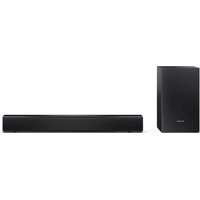
This product is recommended for flat panel TV
(LCD and plasma).
natural_image
Illustration of a remote control unit with a keypad and display screen (no text or symbols)
DOLBY
DIGITAL
VIRTUAL
SPEAKER
PRO LOGIC II

dts ^TM
Digital Surround

WOW HD
SRS(○)
WOW HD
is a trademark of SRS Labs, Inc.
WOW HD technology is incorporated under license from SRS Labs, Inc.
| DEUTSCH | ... Siehe Seiten i bis xii und D-1 bis D-20. |
| FRANÇAIS | ... Se reporter aux pages i à xii et F-1 à F-20. |
| ESPÁNOL | ... Consulte las páginas i a xii y S-1 a S-20. |
| SVENSKA | ... Hänvisa till sidorna i till xii och V-1 till V-20. |
| ITALIANO | ... Leggere le pagine i a xii e l-1 a l-20. |
| NEDERLANDS | ... Raadpleeg de bladzijden i t/m xii en N-1 t/m N-20. |
| PORTUGUÉS | ... Favor consultar as páginas i a xii e P-1 a P-20. |
| 中文 | ... 请参见第i頁到第xii頁和中-1到中-20. |
| ENGLISH | ... Please refer to pages i to xii and E-1 to E-20. |
- When the ON/STAND-BY button is set at STAND-BY position, mains voltage is still present inside the unit. When the ON/STAND-BY button is set at STAND-BY position, the unit may be brought into operation by the remote control.
Warning:
This unit contains no user serviceable parts. Never remove covers qualified to do so. This unit contains dangerous voltages always remove mains plug from the socket before any service operation and when not in use for a long period.
Manufactured under license under U.S. Patent #'s: 5,451,942; 5,956,674; 5,974,380; 5,978,762; 6,487,535 & other U.S. and worldwide patents issued & pending. DTS and DTS Digital Surround are registered trademarks and the DTS logos and Symbol are trademarks of DTS, Inc. © 1996-2007 DTS, Inc. All Rights Reserved.
Manufactured under license from Dolby Laboratories. "Dolby", "Pro Logic", the double-D symbol are trademarks of Dolby Laboratories.
Information on Proper Disposal


Attention: Your product is marked with this symbol. It means that used electrical and electronic products should not be mixed with general household waste. There is a separate collection system for these products.
A. Information on Disposal for Users (private households)
1. In the European Union
Attention: If you want to dispose of this equipment, please do not use the ordinary dustbin!
Used electrical and electronic equipment must be treated separately and in accordance with legislation that requires proper treatment, recovery and recycling of used electrical and electronic equipment.
Following the implementation by member states, private households within the EU states may return their used electrical and electronic equipment to designated collection facilities free of charge*. In some countries* your local retailer may also take back your old product free of charge if you purchase a similar new one.
*) Please contact your local authority for further details.
If your used electrical or electronic equipment has batteries or accumulators, please dispose of these separately beforehand according to local requirements.
By disposing of this product correctly you will help ensure that the waste undergoes the necessary treatment, recovery and recycling and thus prevent potential negative effects on the environment and human health which could otherwise arise due to inappropriate waste handling.
2. In other Countries outside the EU
If you wish to discard this product, please contact your local authorities and ask for the correct method of disposal.
For Switzerland: Used electrical or electronic equipment can be returned free of charge to the dealer, even if you don't purchase a new product. Further collection facilities are listed on the homepage of www.swico.ch or www.sens.ch.
B. Information on Disposal for Business Users
1. In the European Union
If the product is used for business purposes and you want to discard it:
Please contact your SHARP dealer who will inform you about the take-back of the product. You might be charged for the costs arising from take-back and recycling. Small products (and small amounts) might be taken back by your local collection facilities.
For Spain: Please contact the established collection system or your local authority for take-back of your used products.
2. In other Countries outside the EU
If you wish to discard of this product, please contact your local authorities and ask for the correct method of disposal.

Information on Battery Disposal
For EU: The crossed-out wheeled bin implies that used batteries should not be put to the general household waste! There is a separate collection system for used batteries, to allow proper treatment and recycling in accordance with legislation. Please contact your local authority for details on the collection and recycling schemes.
For Switzerland: The used battery is to be returned to the selling point.
For other non-EU countries: Please contact your local authority for correct method of disposal of the used battery.
Introduction
Thank you for purchasing this SHARP product.
To obtain the best performance from this product, please read this manual carefully. It will guide you in operating your SHARP product.
Accessories
Please confirm that only the following accessories are included.
 Remote control x 1 Remote control x 1 |  RCA cable (2 pins - 2 pins) x 1 RCA cable (2 pins - 2 pins) x 1 |
 Spike x 4 (length: 25 mm) Spike x 4 (length: 25 mm) |  Foot cushion x 4 Foot cushion x 4 |
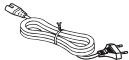 AC power lead x 1 AC power lead x 1 | 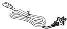 AC power lead x 1(for Taiwan only) AC power lead x 1(for Taiwan only) |
 AC/DC adaptor x 1(RADPAA061AWZZ) AC/DC adaptor x 1(RADPAA061AWZZ) |  Wall mount angle x 2 Wall mount angle x 2 |
Nut (Spike + Nut) x 4 (length: 30 mm) (Spike + Nut) x 4 (length: 30 mm) |  Pattern paper x 1 Pattern paper x 1 |
Note:
The AC/DC adaptor may be different from the one in the drawing.
Features
SRS WOW improves the dynamic audio performance of compressed and uncompressed audio by expanding the size of the audio image and creating a deep, rich bass response.
Contents
Page
■ General Information
Precautions 2
Controls and indicators 3 - 5
■ Preparation for Use
Speaker preparation 6 - 8
Placing the speaker....9
Falling prevention ....10
Speaker connections to TVs. 10 - 12
AC power connection 13
Remote control 14
■ Basic Operation
General control 15 - 17
■ References
Troubleshooting chart 18
Maintenance 19
Error indicators and warnings 19
Specifications 20
General
- Please ensure that the equipment is positioned in a well-ventilated area and ensure that there is at least 10 cm (4") of free space along the sides and top of the equipment.
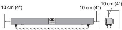
- Use the speaker on a firm, level surface free from vibration.
- Keep the speaker away from direct sunlight, strong magnetic fields, excessive dust, humidity and electronic/electrical equipment (home computers, facsimiles, etc.) which generate electrical noise.
- Do not place anything on top of the speaker.
- Do not expose the speaker to moisture, to temperatures higher than 60°C (140°F) or to extremely low temperatures.
- If your system does not work properly, disconnect the AC power lead from the Wall socket. Plug the AC power lead back in, and then turn on your system.
- In case of an electrical storm, unplug the speaker for safety.
- Hold the AC power plug by the head when removing it from the Wall socket, as pulling the lead can damage internal wires.
- The AC power plug is used as a disconnect device and shall always remain readily operable.
- Do not remove the outer cover, as this may result in electric shock. Refer internal service to your local SHARP service facility.
- This speaker should only be used within the range of 5°C - 35°C (41°F - 95°F).
Warning:
- The voltage used must be the same as that specified on this speaker. Using this product with a higher voltage other than that which is specified is dangerous and may result in a fire or other type of accident causing damage. SHARP will not be held responsible for any damage resulting from use of this speaker with a voltage other than that which is specified.
- The supplied AC/DC adaptor contains no user serviceable parts. Never remove covers unless qualified to do so. It contains dangerous voltages, always remove mains plug from the main outlet socket before any service operation or when not in use for a long period.
- The AC/DC adaptor supplied with the HT-SB300 must not be used with other equipment.
- Never use an AC/DC adaptor other than the one specified. Otherwise, problem or serious hazards may be created.
Volume control
The sound level at a given volume setting depends on speaker efficiency, location, and various other factors. It is advisable to avoid exposure to high volume levels, which occurs whilst turning the speaker on with the volume control setting up high, or whilst continually listening at high volumes.
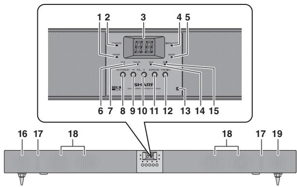
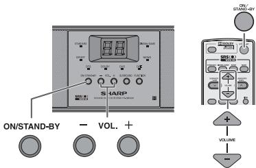
■ Front Panel
Reference page
- Sport Indicator 15
- Standard Indicator 15
- Information Display 15
- Cinema/Game Indicator 15
- News Indicator 15
- DTS Indicator 16
- Dolby Indicator.... 16
- On/Stand-by Button 15
- Volume Down Button 15
- Volume Up Button 15
Reference page
- Surround Button .....15
- Function Button....17
- Remote Sensor ....14
- Dolby Virtual Speaker Indicator .....16
- Dolby Prologic II Indicator .....16
- Left Front Speaker
- Bass Reflex Duct
- Subwoofers
- Right Front Speaker
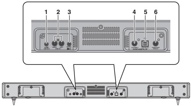
■ Rear Panel
Reference page
- Audio Line In 2 Socket .... 11
- Line In 1 Sockets ...... 11
- DC IN Socket 13
- Coaxial Digital Audio Input Socket 12
- Optical Digital Audio Input Socket 12
- Subwoofer Pre Output Socket 9
Controls and indicators (continued)
Note:
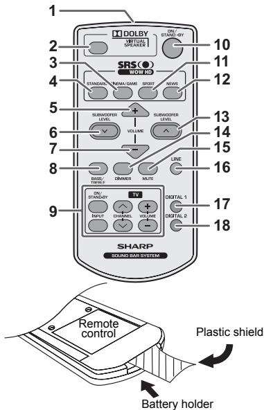
Before using remote control, please remove plastic shield at battery holder.
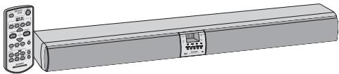
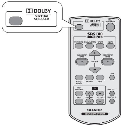
■ Remote Control
Reference page
- Remote Control Transmitter 14
- Dolby Virtual Speaker Button.... 16
- Cinema/Game Button 15
- Standard Button.... 15
- Volume Up Button 15
- Subwoofer Level Down Button.... 17
- Volume Down Button.... 15
- Bass/Treble Button 17
- TV Operation Buttons 5
- On/Stand-by Button.... 15
- Sport Button.... 15
- News Button.... 15
- Subwoofer Level Up Button 17
- Dimmer Button.... 15
- Mute Button 15
- Line Button.... 17
- Digital 1 Button 17
- Digital 2 Button 17
| TV Operation Buttons (Only SHARP TV): | |||
On/Stand-by Button | Sets the TV power to “ON” or “STAND-BY”. | Input Select Button (TV) | Press the button to switch the input source. |
| Volume Up and Down Buttons[0x8y1] | Turn up/down the TV volume. | Channel Up and Down Buttons[0x4y7] | Switch up/down the TV channels. |
Notes:
- Some models of SHARP TV may not be operable.
- SHARP TV remote control will not work with HT-SB300 system.
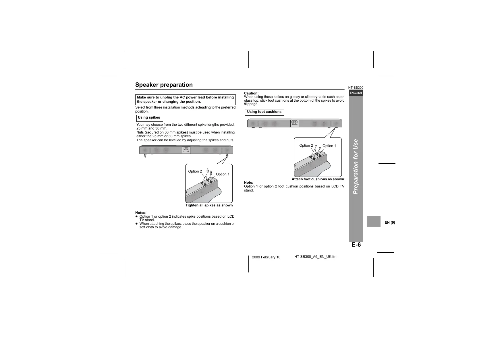
Make sure to unplug the AC power lead before installing the speaker or changing the position.
Select from three installation methods acleading to the preferred position.
Using spikes
You may choose from the two different spike lengths provided: 25 mm and 30 mm.
Nuts (secured on 30 mm spikes) must be used when installing either the 25 mm or 30 mm spikes.
The speaker can be levelled by adjusting the spikes and nuts.
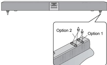
Tighten all spikes as shown
Notes:
- Option 1 or option 2 indicates spike positions based on LCD TV stand.
- When attaching the spikes, place the speaker on a cushion or soft cloth to avoid damage.
Caution:
When using these spikes on glossy or slippery table such as on glass top, stick foot cushions at the bottom of the spikes to avoid slippage.
Using foot cushions
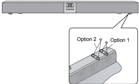
Attach foot cushions as shown
Note:
Option 1 or option 2 foot cushion positions based on LCD TV stand.
Speaker preparation (continued)
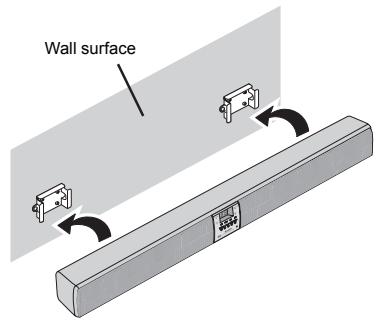
To mount the speaker on the wall
Caution:
- Be very careful to prevent the speaker [1.75 kg (3.86 lbs.)] from falling when mounting on the wall.
- Before mounting, check the wall strength. (Do not put on the veneer plaster or whitewashed wall. The speaker may fall.) If unsure, consult a qualified service technician.
- Mounting screws are not supplied. Use appropriate ones.
- Check all wall mount angle screws for looseness.
- Select a good location. If not, accidents may occur or the speaker may get damaged.
- SHARP is not responsible for accidents resulting from improper installation.
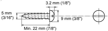
■ Driving screws
SHARP designed the speakers so you may hang them on the wall. Use proper screws (not supplied). See below for size and type.
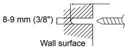
■ Wall mount angle fixed to the wall (Horizontal position)
1 Fix the pattern paper to the wall in horizontal position as below.

2 Make a hole on the wall following the screw point marks on the pattern paper by using a drill.
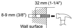
32 mm (1-1/4")
3 Fix a wall mount plug into the hole using a hammer, until it is flush with the wall surface.
(Continued to the next page)
4 Screw the wall mount angle to the wall as shown in the illustration. (Total screw is 8 pieces)
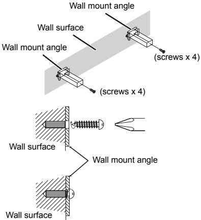
Note:
Make sure all screws are fully tighten. (screws are not supplied)
■ Installing the speaker
1 Align the wall mount slot at the speaker to the wall mount angle.
2 Slot the speaker into the wall mount angle.
3 Fix them securely.
Placing the speaker
Installation image:
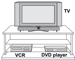
Place the speaker as shown.
Notes:
- As the sound from the speaker is omni-directional, you can place the speaker anywhere you like. However, it is recommended to place it as close to the TV as possible.
● The front panel of the speaker is not removable.
Caution:
- Do not change the installation direction when the speaker is turned on.
- Do not stand or sit on the speaker as you may be injured.
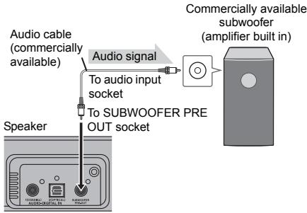
■ Using other subwoofer
You can connect a subwoofer with an amplifier to the SUBWOOFER PRE OUT socket.
flowchart
graph TD
    A["Speaker"] --> B["To SUBWOOFER PRE OUT SOCKET"]
    B --> C["To audio input socket"]
    C --> D["Audio signal"]
    D --> E["Commercially available subwoofer (amplifier built in)"]
    style A fill:#f9f,stroke:#333
    style E fill:#ccf,stroke:#333
Note:
No sound is heard from the subwoofer without a built-in amplifier.
Falling prevention
Safety wires (not supplied) are useful to prevent the speaker from falling off the table.
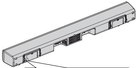
natural_image
Technical line drawing of a mechanical assembly with mounting holes and internal compartments (no text or symbols)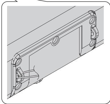
natural_image
Technical line drawing of a mechanical bracket assembly (no text or symbols)Loop the safety wires (not supplied) into each hole as shown and tie the safety wires to the LCD TV stand.
Speaker connections to TVs
Caution:
Turn off all other equipment before making any connections.
Tuner receiving for other audio system
- Placing the aerial near the speaker AC power lead may cause noise pick up. Place the aerial away from the speaker for better reception.
Notes:
- To connect to TV, use either LINE IN 1 sockets or AUDIO LINE IN 2 socket only.
- Refer the operation manual of the equipment to be connected.
- Fully insert the plugs to avoid fuzzy pictures or noises.
Speaker connections to TVs (continued)
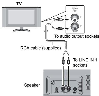
■ Connecting to a TV
If the TV/monitor has an audio output, connect it to the LINE IN 1 sockets on the rear of the speaker.
To select LINE IN 1 function:
- On speaker: Press FUNCTION button repeatedly until "L1" is displayed.
- On remote control: Press LINE button repeatedly until "L1" is displayed.
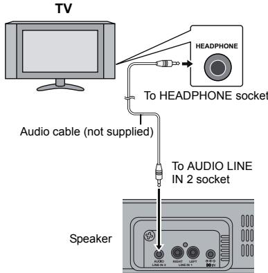
■ Connecting to a TV (with Headphone socket)
If the TV/monitor has headphone socket, connect it to the LINE IN 2 socket on the rear of the speaker.
To select LINE IN 2 function:
- On speaker: Press FUNCTION button repeatedly until "L2" is displayed.
- On remote control: Press LINE button repeatedly until "L2" is displayed.
Notes:
- If the TV volume is continuously in low level, the speaker will automatically power off. Increase the TV output volume to enjoy the sound from the speaker.
- If the speaker volume is continuously in very high level, the speaker will mute and recover after 3 seconds.
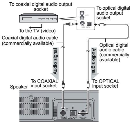
■ Connecting a digital tuner, etc.
Connect to the digital tuner, etc. using an optical digital audio cable or a coaxial digital audio cable.
To select DIGITAL 1 (coaxial input) or DIGITAL 2 (optical input) function:
- On speaker: Press FUNCTION button repeatedly until "d1" or "d2" is displayed.
- On remote control: Press DIGITAL 1 or DIGITAL 2 button and "d1" or "d2" is displayed.
flowchart
graph TD
    A["To coaxial digital audio output socket"] --> B["To the TV (video)"]
    A --> C["To optical digital audio output socket"]
    D["Coaxial digital audio cable (commercially available)"] --> E["Audio signal"]
    F["Speaker"] --> G["To COAXIAL input socket"]
    F --> H["To optical digital audio cable (commercially available)"]
    I["To optical digital audio output socket"] --> J["To optical input socket"]
    K["To COAXIAL input socket"] --> L["To optical digital audio cable (commercially available)"]
Note:
When connecting with an optical digital cable, set the digital output of the digital tuner to PCM. Refer to the operation manual of the digital tuner.
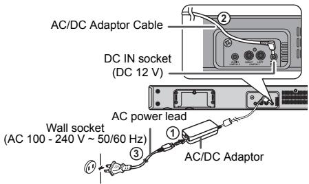
AC power connection
After checking all the connections have been made correctly, connect the AC power lead to the AC power input socket, then to the Wall socket.
■ Using with the AC/DC adaptor
1 Plug the AC power lead into the AC/DC adaptor.
2 Plug the AC/DC adaptor cable into the DC IN socket on the speaker.
3 Plug the AC power lead into an Wall socket. The STAND-BY indicator will turn RED when AC power is applied. The power indicator will turn GREEN when the system in "ON".
Notes:
- Unplug the AC/DC adaptor from the Wall socket if the speaker will not be used for a long period of time.
- Use only the supplied AC/DC adaptor. Using other AC/DC adaptor may cause an electric shock or fire.
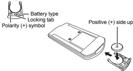
■ Battery installation
1 Insert pin into the hole as shown and pull to open the battery holder.
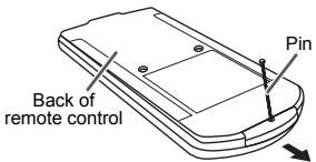
2 Remove the old battery from the battery holder, insert the new battery and then slide the battery holder back into the remote control.
Battery holder
Precautions for battery use:
- Remove the battery if the speaker will not be used for a long period of time. This will prevent potential damage due to battery leakage.
Caution:
- Do not use rechargeable battery (nickel-cadmium battery, etc.).
● Danger of explosion if battery is incorrectly replaced. - Replace only with the same or equivalent type.
- Batteries (battery pack or batteries installed) shall not be exposed to excessive heat such as sunshine, fire or the like.
- Installing the battery incorrectly may cause the speaker to malfunction.
Notes concerning use:
- Replace the battery if the operating distance is reduced or if the operation becomes erratic. Purchase “CR 2025”, coin lithium battery.
- Periodically clean the transmitter on the remote control and the sensor on the speaker with a soft cloth.
- Exposing the sensor on the speaker to strong light may interfere with operation. Change the lighting or the direction of the speaker if this occurs.
- Keep the remote control away from moisture, heat, shock, and vibrations.
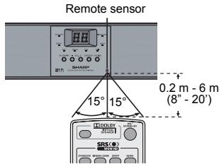
■ Test of the remote control
Point the remote control directly at the remote sensor on the speaker.
The remote control can be used within the range shown below:
Press the ON/STAND-BY button. Does the power turn on? Now, you can enjoy your system.
■ To turn the power on
Press the ON/STAND-BY button.
- The power indicator turns green. If the power does not turn on, check whether the power lead is plugged in properly.
To set the speaker to stand-by mode:
- Press the ON/STAND-BY button again. The STAND-BY indicator turns red.
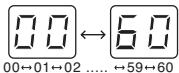
■ Display brightness control
Press the DIMMER button to adjust the brightness of the display and sound mode indicator.
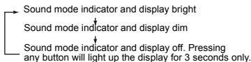
flowchart
graph TD
    A["Sound mode indicator and display bright"] --> B["Sound mode indicator and display dim"]
    B --> C["Sound mode indicator and display off. Pressing any button will light up the display for 3 seconds only."]
■ Volume auto fade-in
If you turn off and on the speaker with the volume set to 40 or higher, the volume starts at 20 and fades in to the last set level.
Volume control
Speaker operation:
Press volume up (VOL. +) to increase the volume and press volume down (VOL. -) to decrease the volume.
Remote control operation:
Press the VOLUME + button to increase the volume and the VOLUME – button to decrease the volume.
■ Muting
The volume is muted temporarily when pressing the MUTE button on the remote control. Press again to restore the volume.

■ Preset sound mode
Main unit operation:
When the SURROUND button is pressed, the current mode setting will light up. To change to a different mode, press the SURROUND button repeatedly until the desired sound mode lights up.
Remote control operation:
Press a desired sound mode on the remote control.
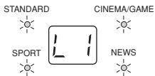
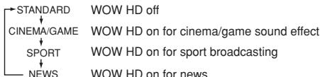
flowchart
graph TD
    A["STANDARD"] --> B["CINEMA/GAME"]
    B --> C["SPORT"]
    C --> D["NEWS"]
    style A fill:#f9f,stroke:#333
    style B fill:#ccf,stroke:#333
    style C fill:#cfc,stroke:#333
    style D fill:#fcc,stroke:#333
■ Dolby Virtual Speaker (DVS) sound mode
The Dolby Virtual Speaker (DVS) creates virtual surrounds comparable to the 5.1ch sound produced by the 2.1ch speaker. When setting DVS to "ON" for 2 channel stereo signals, Dolby Pro Logic II brings out virtual sound effects through the signals converted into 5.1ch.
Press the DVS button.
The Dolby Virtual Speaker indicator lights up.
Notes:
- Monaural signals do not generate surround effects.
- DVS sound effect may not be obtained depending on signal types (the Dolby Virtual Speaker indicator blinks). In this case, set the DVS mode to "OFF".
ON
The Dolby Virtual Speaker creates multichannel-like sound effects.
Compared with the cinema mode, the bass sound level is slightly reduced.
The Dolby Pro Logic II indicator also lights up if 2ch sound signals are detected.
● DVS can only be turned on using remote control.
- If you turn ON DVS, WOW HD will automatically turn OFF.
- The DVS can be turned OFF by pressing any of the preset sound mode buttons.
This product incorporates decoders supporting the Dolby Digital system and DTS system.
DTS (Dig Systems)
Theatre
One of the digital audio systems for theatrical use. As the sound quality is emphasised, you can enjoy the realistic sound effect in the home theatre system.
Lights up when detecting DTS signal.
Dolby Digital
One of the digital audio systems for theatrical use. You can also enjoy the stereophonic effect in the home theatre system.
Lights up when detecting Dolby Digital signal.
General control (continued)
Dolby Pro Logic II
System expanding 2ch stereo sound to more spacious sound. When setting Dolby Virtual speaker to "ON", Dolby Pro Logic II is activated to enjoy the stereo sound effect. Lights up when Dolby Pro Logic II is activated.
■ Subwoofer level control
The speaker level can be adjusted.
To increase the level, press the SUBWOOFER LEVEL + button.
To decrease the level, press the SUBWOOFER LEVEL – button.
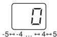
Note:
When sound from the speaker is distorted, decrease the subwoofer level.
■ Bass control
-
Press the BASS/TREBLE button to select "BASS".
-
Within 5 seconds, press the VOLUME (+ or −) button to adjust the bass.
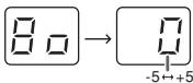
■ Treble control
-
Press the BASS/TREBLE button to select "TREBLE".
-
Within 5 seconds, press the VOLUME (+ or −) button to adjust the treble.
![Γ Γ → [ ] -5←+5](/content/2025/01/79028/images/ec3db43df52d062494d8fe13b75839f1ee559565188ae8ab804a17261a917df2.jpg)
Function
On speaker:
When the FUNCTION button is pressed, the input source will change. Press it repeatedly to select desired input source.
On remote control:
Press the LINE button repeatedly to select "L1" (LINE IN 1 input) or "L2" (LINE IN 2 input).
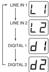
flowchart
graph TD
    A["LINE IN 1"] --> B["L1"]
    A --> C["LINE IN 2"]
    C --> D["L2"]
    C --> E["DIGITAL 1"]
    E --> F["d1"]
    E --> G["DIGITAL 2"]
    G --> H["d2"]
Note:
The backup function will protect the memorised function mode for a few hours should there be a power failure or the AC power lead becomes disconnected.
Auto power on function:
When you press the LINE / DIGITAL 1 / DIGITAL 2 button on the remote control, the speaker will turn on at the selected function.
Auto power off and auto detect signal:
- If no analogue signal is detected within 1 minute or if "d1"/"d2" display is blinking for 30 seconds during power on, the speaker will automatically go to stand-by mode. The STAND-BY indicator turns orange.
- The speaker will automatically power ON if it detects audio signal from connected equipment.
Troubleshooting chart
Many potential problems can be resolved by the owner without calling a service technician.
If something is wrong with this product, check the following before calling your authorised SHARP dealer or service centre.
General
| Symptom | Possible cause |
| No sound is heard. | ● Is the input signal (selection) set properly? ● Is the volume level set to “0”? ● Is muting activated? |
| Noise is heard during playback. | ● Move the speaker away from any computers or mobile phones. |
| When a button is pressed, the speaker does not respond. | ● Set this speaker to the stand-by mode and then turn it back on. |
| The power is not turned on. | ● Is the speaker unplugged? (Refer to page 17) ● The protection circuit may be activated. Unplug and plug in the power lead again after 5 minutes or more. |
| The information is not displayed even if the unit is turned on. | ● Is the unit set to “Dimmer display off” mode? |
■ Remote control
| Symptom | Possible cause |
| The remote control does not operate properly. | Is the battery polarity correct?Is the battery dead?Is the distance or angle incorrect?Are there any obstructions in front of the speaker?Is there a strong light shining on the remote sensor?Is the remote control for another equipment used simultaneously? |
| Symptom | Possible cause |
| The speaker cannot be turned on with the remote control. | Is the AC power lead of the speaker plugged in?Is the battery inserted? |
| TV cannot be operated with the remote control. | Depending on the model, some or all functions may not be operable using the remote control of this speaker. In this case, use the remote control supplied with the TV. |
■ Condensation
Sudden temperature changes, storage or operation in an extremely humid environment may cause condensation inside the cabinet or on the transmitter on the remote control.
Condensation can cause the speaker to malfunction. If this happens, leave the power on until normal operation is possible (about 1 hour). Wipe off any condensation on the transmitter with a soft cloth before operating the speaker.
■ If problem occurs
When this product is subjected to strong external interference (mechanical shock, excessive static electricity, abnormal supply voltage due to lightning, etc.) or if it is operated incorrectly, it may malfunction.
If such a problem occurs, do the following:
- Set the speaker to the stand-by mode and turn the power on again.
- If the speaker is not restored in the previous operation, unplug and plug in the speaker, and then turn the power on.
Maintenance
■ Cleaning the cabinet
Periodically wipe the cabinet with a soft cloth.
Caution:
- Do not use chemicals for cleaning (petrol, paint thinner, etc.). It may damage the cabinet finish.
- Do not apply oil to the inside of each component. It may cause malfunctions.
natural_image
Illustration of a hand pressing down on a device with sparkles above (no text or symbols)Error indicators and warnings
When you fail to perform operations properly, the following messages are displayed on the speaker.
| Display | Meaning |
[8wc8]or or or | Malfunction of the surround circuit. Place the speaker away from noise source and plug the AC power lead into another AC outlet. (*) |
 or or (Display blinks continuously) (Display blinks continuously) | When there is no input signal. Play back the connected equipment.Nonstandard signal. Cannot be recognized. Signals other than DOLBY DIGITAL, DTS, Linear PCM cannot be recognized.Poor connection of the digital audio input terminal.Turn off the unit and check if the cable is connected properly. |
| Power indicator (blinks red) | When the protection circuit is activated. |
(*): Should the same message appear even if the speaker is unplugged and plugged in or is set to the stand-by mode and on again, contact your local dealer where you purchased the speaker.
Specifications
As part of our policy of continuous improvement, SHARP reserves the right to make design and specification changes for product improvement without prior notice. The performance specification figures indicated are nominal values of production speaker. There may be some deviations from these values in individual speaker.
■ General
| Power source | DC IN 12V === 4A: AC/DC adaptor (AC 100 - 240 V ~ 50/60 Hz) |
| Power consumption | Power on: 11 WPower stand-by: 0.6 W (*) |
| Output power | Front speaker:RMS: 12 W (6 W + 6 W) (10% T.H.D.)RMS: 9.6 W (4.8 W + 4.8 W) (0.9% T.H.D.)Subwoofer:RMS: 20 W (10% T.H.D.)RMS: 13 W (0.9% T.H.D.) |
| Speaker | 2.1-way Speaker SystemFront speakers: 38 mm (1-1/2") Full RangeImpedance: 12 ohms / ChannelSubwoofer: 57 mm (2-1/4") Woofer (x4)Impedance: 3 ohms(12 ohms x 4 parallel connections) |
| Audio output terminals | Subwoofer Pre Out: 10 kohms |
| Input terminals | Analogue input (LINE 1):RCA type x 1pair (L/R)500 mV / 47 kohmsAnalogue input (LINE 2):Stereo mini socket ∅ 3.5 mm100 mV / 47 kohmsCoaxial digital input (DIGITAL 1):RCA type x 1Optical digital input (DIGITAL 2):Square type x 1 |
| Dimensions | Width: 800 mm (31-1/2")Height: 96 mm (3-3/4")Depth: 70 mm (2-3/4") |
| Weight | 1.85 kg (4.10 lbs.) |
(*) This power consumption value is obtained when in the power stand-by mode.