LIC30H-A - Uncategorized Black Box - Free user manual and instructions
Find the device manual for free LIC30H-A Black Box in PDF.


User questions about LIC30H-A Black Box
0 question about this device. Answer the ones you know or ask your own.
Ask a new question about this device
Download the instructions for your Uncategorized in PDF format for free! Find your manual LIC30H-A - Black Box and take your electronic device back in hand. On this page are published all the documents necessary for the use of your device. LIC30H-A by Black Box.
USER MANUAL LIC30H-A Black Box
natural_image
Illustration of a two-wheeled cart with a door and wheels (no text or symbols)
BLACK BOX
TABLE OF CONTENTS
SAFETY INFORMATION/ELECTRICAL PRECAUTIONS 3
Important Safety Information....3
Electrical Precautions....3
1. SPECIFICATIONS......4
1.1 Standard Intelligent Charging Carts General Specifications....4
1.2 Standard Intelligent Charging Carts Specifications for Hinged Door 5
2. OVERVIEW....6
2.1 Introduction....6
2.2 What's Included 6
3. CONFIGURATION AND SETUP....7
3.1 Unpacking 7
3.2 Routing the Cables....7
3.3 Using the Intelligent Charging System....10
3.3.1 Display Tour 10
3.3.2 To Begin Charging....11
3.3.3 Basic Functions....11
3.4 Plugging In the Cart 12
3.5 Turning On the Cart 12
3.6 Moving the Cart 13
APPENDIX A. REGULATORY INFORMATION....14
A.1 FCC Statement....14
A.2 NOM Statement (Electrical Safety)....14
APPENDIX B. ADDITIONAL DIMENSIONS....16
TRADEMARKS USED IN THIS MANUAL....17
SAFETY INFORMATION/ELECTRICAL PRECAUTIONS
IMPORTANT SAFETY INFORMATION
WARNING! Death or serious injury may occur when children climb on the Cart. The cart can tip over onto the child.
WARNING! Avoid uneven loading of equipment onto the cart. Uneven weight distribution could cause the cart to tip when the cart is moving. Ensure devices are distributed evenly within the cart. Excess weight on sides of cart could cause the cart to tip while in motion.
- Only adults should move the cart.
- Do not leave the cart unattended in areas where children have access.
- Do not block the air vent openings.
- The Cart can be very heavy when fully loaded with laptops and should be moved about by persons physically able to do so.
- The Cart should only be used for the storage and transport of tablets, laptops, and other similar devices.
- Misuse, incorrect operation, or inadequate repair of the Cart will void the warranty.
ELECTRICAL PRECAUTIONS
DANGER! Failure to observe the following electrical safety precautions can result in fire or death by electric shock.
- The power switch must be in the "OFF" position before plugging the Cart into a wall receptacle.
- The Cart must ONLY be connected to a 110–120-volt AC, 15-amp power supply.
- The Cart must only be used by adults or with adult supervision.
- Never pull the Cart by the power cord.
Do not plug the Cart in if the switch, receptacle(s), or power cord has been damaged. All electrical components on this product must be repaired by a qualified electrician.
- Do not use an extension cord in conjunction with the Cart.
- Do not use liquids in or around the Cart environment.
- Inadequate repair or modifications can create significant hazards to users and are not covered by warranty.
For your safety, we recommend that a qualified electrician test the circuit you will be plugging the Cart into. The circuit should be checked for ground integrity and appropriate branch circuit protection.
The Cart ground prong must be present for safe operation. If the plug is damaged or if the ground prong has been removed, it should be replaced by a qualified electrician.
The use of the Cart, including plugging or unplugging laptops, plugging or unplugging the Cart, operating the control switch, and engaging or releasing the directional and locked casters, must be done with adult supervision.
All electrical outlets provided are for the sole purpose of charging electronic devices. Any use of these electrical outlets, other than for the intended purpose, is not advised and must be approved by a qualified electrician.
Do not exceed the maximum specified wattage of the cart. The load current shall not exceed 12 amps under any operating conditions.
1.1 STANDARD INTELLIGENT CHARGING CARTS GENERAL SPECIFICATIONS
TABLE 1-1. GENERAL SPECIFICATIONS
| SPECIFICATION DESCRIPTION | |
| General | |
| Approvals UL | * 60950 Approved; UL 1678 - Tip Test Compliant, CE, RoHS2 |
| Use Indoor office and mobile use only | |
| Assembled Yes | |
| Material 18 ga (1.2 mm) minimum thick steel | |
| Construction Fully welded box frame, riveted and bolted panels | |
| Finish Powder Coat | |
| Color | Gray |
| Electrical | |
| Input Power 120 VAC, 15 A, 50-60 Hz, 1 Ph | |
| Input Power Cord | NEMA5-15P plug, min. 6-ft. (1.8-m) cord |
| Power Cord Access | (2) 1.3" (3.3 cm) DIA holes (Left and Right rear bottom corner) |
| On/Off Switch | (1) illuminated switch on charging unit |
| Device Charging Type | Intelligent Power Charger: Charged Mode or Managed Mode |
| Cart Max. Current Rating | 12 amps |
| Auxiliary Power | (1) NEMA5-15R on intelligent charging unit (for units w/o external power); (3) NEMA5-15R and (2) USB 2.0 Type A Outlets (external power option only) |
| Dimensions | |
| Unit Height 44.1" (112.0 cm) | |
| Unit Width | 20.2" (51.3 cm) w/o handle, 23.7" (60.2 cm) w/ handle |
| Unit Depth | 21.3" (54.1 cm) |
| Unit Weight | 125 lb. (56.8 kg) |
| Shipping Height | 50" (127 cm) |
| Shipping Width | 35" (88.9 cm) |
| Shipping Depth | 32" (81.3 cm) |
| Shipping Weight | 150 lb. (68.2 kg) |
| Top Weight Capacity | 150 lb. (68.2 kg) |
| Frame | |
| Ventilation | Min. 75% high flow steel mesh, (2) places per shelf |
| Top | 2.00-mm thick steel top |
| Casters | |
| Type | (2) Fixed, (2) Swiveling and Locking |
| Diameter | 5" (12.7 cm) |
| Wheel | Polyurethane tread |
| Frame | Nickel Plated Steel |
| Warranty | |
| Cart | Lifetime |
| Electronics | 3 Years |
1.2 STANDARD INTELLIGENT CHARGING CARTS SPECIFICATIONS FOR HINGED DOOR
TABLE 1-2. STANDARD INTELLIGENT CHARGING CARTS SPECIFICATIONS FOR HINGED DOOR
| PART NUMBER TYPICAL | DEVICE QUANTITY | EXTERNAL POWER | FRONT CABLE MANAGEMENT | LOCK TYPE | MAX. DEVICE SIZE (INCHES) MAX. WALLMOUNT POWER SUPPLY SIZE (INCHES) | MAX. POWER BRICK SIZE (INCHES) | ||||||||
| HEIGHT | WIDTH | DEPTH | HEIGHT | WIDTH | DEPTH | HEIGHT | WIDTH | DEPTH | ||||||
| LIC30H-A | Tablet or 15" Chromebook | 30 | No | No | Key lock | 10.5 | 1.59 | 14.5 | 2.4 | 1.1 | *SEE BELOW | 5.1 | 1.77 | 5.7 |
| LIC30H-A-HASP | Tablet or 15" Chromebook | 30 | No | No | Padlock | 10.5 | 1.59 | 14.5 | 2.4 | 1.1 | *SEE BELOW | 5.1 | 1.77 | 5.7 |
| LIC30H-AP | Tablet or 15" Chromebook | 30 | Yes | No | Key lock | 10.5 | 1.59 | 14.5 | 2.4 | 1.1 | *SEE BELOW | 5.1 | 1.77 | 5.7 |
| LIC30H-AP-HASP | Tablet or 15" Chromebook | 30 | Yes | No | Padlock | 10.5 | 1.59 | 14.5 | 2.4 | 1.1 | *SEE BELOW | 5.1 | 1.77 | 5.7 |
| LIC36H-A | Tablet or 15" Chromebook | 36 | No | No | Key lock | 10.5 | 1.3 | 14.5 | 2.4 | 1.1 | *SEE BELOW | 5.1 | 1.47 | 5.7 |
| LIC36H-A-HASP | Tablet or 15" Chromebook | 36 | No | No | Padlock | 10.5 | 1.3 | 14.5 | 2.4 | 1.1 | *SEE BELOW | 5.1 | 1.47 | 5.7 |
| LIC36H-AP | Tablet or 15" Chromebook | 36 | Yes | No | Key lock | 10.5 | 1.3 | 14.5 | 2.4 | 1.1 | *SEE BELOW | 5.1 | 1.47 | 5.7 |
| LIC36H-AP-HASP | Tablet or 15" Chromebook | 36 | Yes | No | Padlock | 10.5 | 1.3 | 14.5 | 2.4 | 1.1 | *SEE BELOW | 5.1 | 1.47 | 5.7 |
| LIC30H-AC | Tablet or 15" Chromebook | 30 | No | Yes | Key lock | 10.5 | 1.59 | 14.5 | 2.4 | 1.1 | *SEE BELOW | 5.1 | 1.77 | 5.7 |
| LIC30H-AC-HASP | Tablet or 15" Chromebook | 30 | No | Yes | Padlock | 10.5 | 1.59 | 14.5 | 2.4 | 1.1 | *SEE BELOW | 5.1 | 1.77 | 5.7 |
| LIC30H-ACP | Tablet or 15" Chromebook | 30 | Yes | Yes | Key lock | 10.5 | 1.59 | 14.5 | 2.4 | 1.1 | *SEE BELOW | 5.1 | 1.77 | 5.7 |
| LIC30H-ACP-HASP | Tablet or 15" Chromebook | 30 | Yes | Yes | Padlock | 10.5 | 1.59 | 14.5 | 2.4 | 1.1 | *SEE BELOW | 5.1 | 1.77 | 5.7 |
| LIC36H-AC | Tablet or 15" Chromebook | 36 | No | Yes | Key lock | 10.5 | 1.3 | 14.5 | 2.4 | 1.1 | *SEE BELOW | 5.1 | 1.47 | 5.7 |
| LIC36H-AC-HASP | Tablet or 15" Chromebook | 36 | No | Yes | Padlock | 10.5 | 1.3 | 14.5 | 2.4 | 1.1 | *SEE BELOW | 5.1 | 1.47 | 5.7 |
| LIC36H-ACP | Tablet or 15" Chromebook | 36 | Yes | Yes | Key lock | 10.5 | 1.3 | 14.5 | 2.4 | 1.1 | *SEE BELOW | 5.1 | 1.47 | 5.7 |
| LIC36H-ACP-HASP | Tablet or 15" Chromebook | 36 | Yes | Yes | Padlock | 10.5 | 1.3 | 14.5 | 2.4 | 1.1 | *SEE BELOW | 5.1 | 1.47 | 5.7 |
*Towards Shelf: 1.38*
Towards Rear Door: 3.86*
NOTES:
◆ Height: vertical dimensions, runs top to bottom of cart
- Width: horizontal dimensions, runs left side panel to right side panel of cart
♦ Depth: horizontal dimension, runs front door to rear door of cart
NOTES:
For maximum wallmount power supply dimensional diagrams and maximum power brick dimensional diagrams, see Appendix B.
2.1 INTRODUCTION
The Standard Intelligent Charging Cart is designed to store, charge and transport tablets, e-readers, laptops, netbooks, Chromebooks and other similar devices. Each cart plugs into a typical 120-V, 15-A outlet. The units come equipped with an Intelligent Charging System that efficiently charges devices in either Charged Mode or Managed Mode while ensuring the cart won't overload the electrical circuit.
The Standard Intelligent Charging Cart can be equipped in various configurations according to the following standard options.
• 30 or 36 stored devices
- Split hinged steel front door
- Keyed front and back lock or padlock front and back lock
- External power outlets
• Intelligent Charging System
- Front cable management
All Standard Intelligent Charging Carts feature a heavy-duty, fully welded steel frame, 2.0-thick steel top, and heavy-duty, 5" casters.
Please know and understand the configuration of your cart and read these operating instructions carefully. The manual contains important information concerning the use and safety of your cart and the operators. This cart must be used for its intended purpose only and in accordance with these operating instructions.
2.2 WHAT'S INCLUDED
Your package should contain the following items. If anything is missing or damaged, contact Black Box Technical Support at 877-877-2269 or info@blackbox.com.
(1) Cart
(2) sets of keys
CHAPTER 3: CONFIGURATION AND SETUP
NEED HELP? LE AVE THE TECH TO US
LIVE 24/7 TECHNICAL SUPPORT
1.8 7 7.87 7.2269
3.1 UNPACKING
Remove and discard all packaging materials and lock the lockable casters.
Open and inspect the cart to verify all doors, locks, and casters are working properly.
Do not plug the cart into a wall outlet until all configurations and setup are complete.
3.2 ROUTING THE CABLES
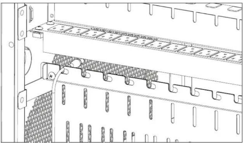
- At the back of the cart, loosen the two screws on the cable manager, slide the top section of the cable manager, and place the device side of the charging cable into one of the slots. See Figure 3-1.
natural_image
Technical line drawing of an internal server rack with connector racks and mounting brackets (no text or symbols)FIGURE 3-1. CABLE ROUTING DIAGRAM #1
- Slide back the top section of the cable manager and tighten the screws.
- Route the device side of the charging cable to the front of the cart.
CHAPTER 3: CONFIGURATION AND SETUP
NEED HELP? LE AVE THE TECH TO US
LIVE 24/7 TECHNICAL SUPPORT
1.8 7 7.87 7.2269
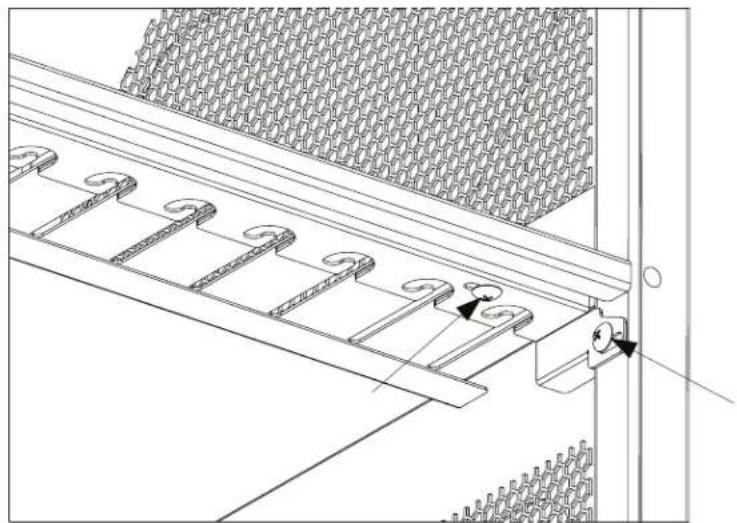
- At the front of the cart, loosen the screws on the side and front of the cable manager.
natural_image
Technical line drawing of a mechanical assembly with spring-like components and a door handle (no text or symbols)FIGURE 3-2. CABLE ROUTING DIAGRAM #2
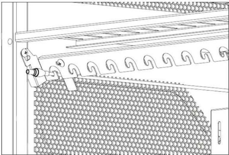
- Push back and down on the front cable manager to drop it down and make it accessible. Slide the top section and place the charging cable into the slots.
natural_image
Technical line drawing of a mechanical assembly with hexagonal grid pattern and tool (no text or symbols)FIGURE 3-3. CABLE ROUTING DIAGRAM #3
CHAPTER 3: CONFIGURATION AND SETUP
NEED HELP? LE AVE THE TECH TO US
LIVE 24/7 TECHNICAL SUPPORT
1.8 7 7.87 7.2269
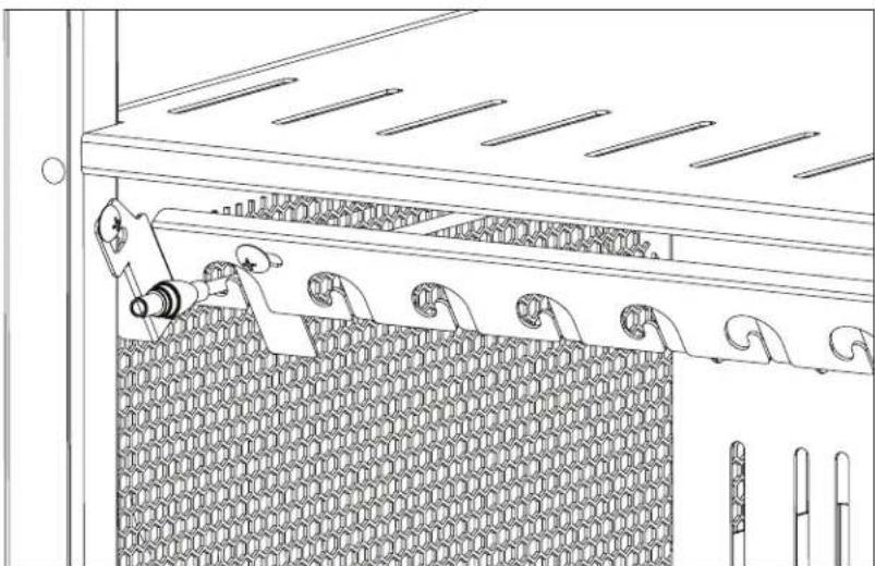
- Slide back the top section and tighten the front screws.
natural_image
Technical line drawing of a mechanical assembly with clamps and a meshed wall (no text or symbols)FIGURE 3-4. CABLE ROUTING DIAGRAM #4
- Push up and pull back on the cable manager to secure it.
- Wrap any excess cable around the cable wrap on the back of the shelf.
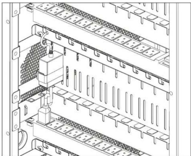
- Attach the power brick to the back of the shelf using the hook and loop strap.
- Plug the charger power plug into the power strip located below the shelf.
natural_image
Technical line drawing of an electrical enclosure with internal panel layout and mounting hardware (no text or symbols)FIGURE 3-5. CABLE ROUTING DIAGRAM #5
CHAPTER 3: CONFIGURATION AND SETUP
NEED HELP? LE AVE THE TECH TO US
LIVE 24/7 TECHNICAL SUPPORT
1.8 7 7.87 7.2269
3.3 USING THE INTELLIGENT CHARGING SYSTEM
The Intelligent Charging System Module arrives installed in your cart.
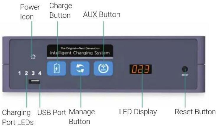
3.3.1 DISPLAY TOUR
text_image
Power Icon Charge Button AUX Button The Original—Next Generation Intelligent Charging System 1 2 3 4 Charging Port LEDs USB Port Manage Button LED Display Reset ButtonFIGURE 3-6. FRONT OF THE INTELLIGENT CHARGING SYSTEM UNIT
text_image
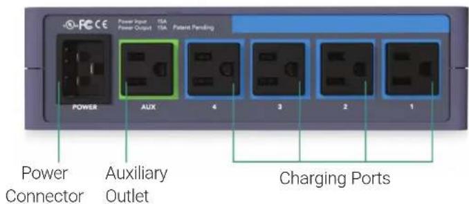
Power Connector Auxiliary Outlet Charging PortsFIGURE 3-7. BACK OF THE INTELLIGENT CHARGING SYSTEM UNIT
CHAPTER 3: CONFIGURATION AND SETUP
NEED HELP? LE AVE THE TECH TO US
LIVE 24/7 TECHNICAL SUPPORT
1.8 7 7.87 7.2269
3.3.2 TO BEGIN CHARGING
- Connect to Power
- Select Charging Mode (Choose from Charge Mode or Manage Mode.)
CHARGE MODE: Best used if all devices are powered off and connected at the same time. Power is discontinued when batteries reach full charge to conserve energy.

MANAGE MODE: Best used if all or some devices are left on or are returned at different times. Charging continues until it is manually stopped.
NOTE: THE CHARGING SYSTEM SHOULD ALWAYS BE IN MANAGE MODE IN ORDER TO CHARGE IPADS AND DEVICES THAT REMAIN IN SLEEP MODE.
3.3.3 BASIC FUNCTIONS

CHARGE BUTTON
Pressing the CHARGE button will start charge mode. This is best used when all devices are powered down and returned to the cart at the same time. Charging will automatically stop when all batteries are 100% charged. You can also stop charging at any time by pressing the CHARGE button a second time.

MANAGE BUTTON
Pressing the MANAGE button will start manage mode and turn on the auxiliary power. This mode will continuously monitor and distribute power until manually stopped. This mode is best used if some of the devices may be left on when connected or if devices are connected at different times. Press the button again to stop manage mode.
CHAPTER 3: CONFIGURATION AND SETUP
NEED HELP?
LE AVE THE TECH TO US
LIVE 24/7
TECHNICAL
SUPPORT
1.8 7 7.87 7.2269

AUXILIARY POWER BUTTON
Pressing the AUXILIARY POWER button controls power to any peripherals that are plugged into the AUX power strip in the back of the cart. If the AUX devices must be operational during charging then the system must be in manage mode. Be aware that this may lengthen charging time.
1 2 3 4
CHARGING PORT LEDS
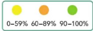
Indicates which sections of the cart are active. The charging unit controls this automatically, ensuring that all devices inside are charged in the fastest, most efficient way possible. When all four quadrant LEDs are solid green, charging is complete.

POWER ICON
Indicates when the cart is connected to power and ready.

RESET
RESET BUTTON
The Intelligent Charging System is protected with its own circuit breaker. If it encounters misuse such as plugging in unsupported devices or if there is a power surge, the circuit will trip and the reset button will pop out. To reset the cart simply press it back in. Please first ensure that everything is plugged in properly and that only supported devices are connected before resetting.
3.4 PLUGGING IN THE CART
After the devices have been loaded into the Cart, plug the power cord of the Cart into a suitable receptacle.
3.5 TURNING ON THE CART
Locate the internal power switches on the power strips of the Cart and push the switches to the ON position. Press the power button on the intelligent charging unit on the outside of the cart. Power strips and charging unit will illuminate if powered. Use as directed.
CHAPTER 3: CONFIGURATION AND SETUP
NEED HELP?
LE AVE THE TECH TO US
LIVE 24/7
TECHNICAL
SUPPORT
1.8 7 7.87 7.2269
3.6 MOVING THE CART
- Remove the Cart plug from the wall receptacle and wrap the cord around the cord wrap or handle.
◆ Close and lock the hinged or sliding doors.
◆ Unlock the locking and swiveling casters before moving the cart to a new location. - When you reach your destination, lock the casters to prevent the cart from moving and plug the cart into a wall receptacle.
A.1 FCC STATEMENT
This equipment generates, uses, and can radiate radio-frequency energy, and if not installed and used properly, that is, in strict accordance with the manufacturer's instructions, may cause interference to radio communication. It has been tested and found to comply with the limits for a Class A computing device in accordance with the specifications in Subpart B of Part 15 of FCC rules, which are designed to provide reasonable protection against such interference when the equipment is operated in a commercial environment. Operation of this equipment in a residential area is likely to cause interference, in which case the user at his own expense will be required to take whatever measures may be necessary to correct the interference.
Changes or modifications not expressly approved by the party responsible for compliance could void the user's authority to operate the equipment.
This digital apparatus does not exceed the Class A limits for radio noise emission from digital apparatus set out in the Radio Interference Regulation of Industry Canada.
APPENDIX B: ADDITIONAL DIMENSIONS
NEED HELP?
LE AVE THE TECH TO US
LIVE 24/7
TECHNICAL
SUPPORT
1.8 7 7.87 7.2269
MAXIMUM WALLMOUNT POWER SUPPLY DIMENSIONS
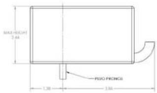
text_image
MILK-VELE(H) 2.44 PUO PRONGI 1.30 1.50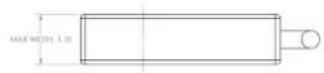
MAXIMUM POWER BRICK DIMENSIONS FOR 10-SLOT PER SHELF CONFIGURATION
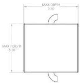
text_image
MAX DEPTH 5.10 MAX HEIGHT 5.10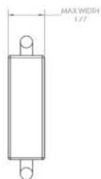
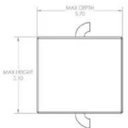
MAXIMUM POWER BRICK DIMENSIONS FOR 12-SLOT PER SHELF CONFIGURATION
text_image
MAX DEPTH 5.70 MAX HEIGHT 5.10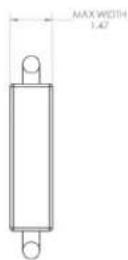
TRADEMARKS USED IN THIS MANUAL
NEED HELP?
LE AVE THE TECH TO US
LIVE 24/7
TECHNICAL
SUPPORT
1.8 7 7.87 7.2269
Black Box and the Double Diamond logo are registered trademarks of BB Technologies, Inc.
UL is a registered trademark of Underwriters' Laboratories.
Any other trademarks mentioned in this manual are acknowledged to be the property of the trademark owners.
NOTES
NEED HELP?
LE AVE THE TECH TO US
LIVE 24/7
TECHNICAL
SUPPORT
1.8 7 7.87 7.2269
NOTES
NEED HELP?
LE AVE THE TECH TO US
LIVE 24/7
TECHNICAL
SUPPORT
1.8 7 7.87 7.2269
NEED HELP?
LEAVE THE TECH TO US
LIVE 24/7
TECHNICAL
SUPPORT
1.87 7.8 7 7.2 269