
AVSC-0401H - Video switch Black Box - Free user manual and instructions
Find the device manual for free AVSC-0401H Black Box in PDF.


| Product Type | 4x1 HDMI Switcher |
| Input Ports | 4 x HDMI (Type A female) |
| Output Ports | 1 x HDMI (Type A female) |
| Supported Resolutions | 480p, 720p, 1080p, 4K@30Hz |
| Video Bandwidth | 10.2 Gbps |
| HDCP Support | HDCP 1.4 |
| Audio Support | LPCM 7.1, Dolby TrueHD, DTS-HD Master Audio |
| Switching Control | Manual push-button, IR remote |
| Dimensions (W x D x H) | 4.5 x 2.5 x 1.0 inches (114 x 64 x 25 mm) |
| Weight | 0.5 lb (227 g) |
| Power Supply | 5V DC, 1A (micro-USB) |
| Power Consumption | 2.5 W (max) |
| Operating Temperature | 32°F to 104°F (0°C to 40°C) |
| Storage Temperature | -4°F to 140°F (-20°C to 60°C) |
| Color | Black |
| Mounting Options | Desktop, optional rack mount bracket |
| Regulatory Approvals | CE, FCC |
| Warranty | Limited 3-year warranty |
| Accessories Included | Power adapter, IR remote, user manual |
Frequently Asked Questions - AVSC-0401H Black Box
User questions about AVSC-0401H Black Box
0 question about this device. Answer the ones you know or ask your own.
Ask a new question about this device
Download the instructions for your Video switch in PDF format for free! Find your manual AVSC-0401H - Black Box and take your electronic device back in hand. On this page are published all the documents necessary for the use of your device. AVSC-0401H by Black Box.
USER MANUAL AVSC-0401H Black Box
Presentation Switcher - HDBaseT, 4 x 1
User Manual
Trademarks Used in this Manual
Black Box and the Double Diamond logo are registered trademarks of BB Technologies, Inc.
Any other trademarks mentioned in this manual are acknowledged to be the property of the trademark owners.
Disclaimer
Black Box Network Services shall not be liable for damages of any kind, including, but not limited to, punitive, consequential or cost of cover damages, resulting from any errors in the product information or specifications set forth in this document and Black Box Network Services may revise this document at any time without notice.
FEDERAL COMMUNICATIONS COMMISSION AND INDUSTRY CANADA RADIO FREQUENCY INTERFERENCE STATEMENTS
This equipment generates, uses, and can radiate radio-frequency energy, and if not installed and used properly, that is, in strict accordance with the manufacturer's instructions, may cause interference to radio communication. It has been tested and found to comply with the limits for a Class A computing device in accordance with the specifications in Subpart B of Part 15 of FCC rules, which are designed to provide reasonable protection against such interference when the equipment is operated in a commercial environment. Operation of this equipment in a residential area is likely to cause interference, in which case the user at his own expense will be required to take whatever measures may be necessary to correct the interference.
Changes or modifications not expressly approved by the party responsible for compliance could void the user's authority to operate the equipment.
This digital apparatus does not exceed the Class A limits for radio noise emission from digital apparatus set out in the Radio Interference Regulation of Industry Canada.
- Do not expose this apparatus to rain, moisture, dripping or splashing water and do not place objects filled with liquids, such as vases, on the apparatus.
- Do not install or place this unit in a bookcase, built-in cabinet or in another confined space. Make sure the unit is well ventilated.
- To prevent risk of electric shock or fire hazard caused by overheating, do not obstruct the unit's ventilation openings with newspapers, tablecloths, curtains, and similar items.
- Do not install near any heat sources such as radiators, heat registers, stoves, or other apparatus (including amplifiers) that produce heat.
- Do not place sources of flames, such as lighted candles, on the unit.
- Clean this apparatus only with a dry cloth.
- Unplug this apparatus during lightning storms or when unused for long periods of time.
- Protect the power cord from being walked on or pinched particularly at plugs.
- Only use attachments/accessories specified by the manufacturer.
- Refer all servicing to qualified service personnel.
Table of Contents
- Specifications 8
- Overview....10
2.1 Introduction....10
2.2 Features 10
2.3 What's Included....11
2.4 Hardware Description 12
2.5 Typical Application....14
- RS-232 Connection 15
3.1 API Commands....15
3.2 Auto Mode....18
- Set and Scaler 19
4.1 Set 19
4.2 Scaler 20
- Specifications
| Video | |
| Input Connectors (2) HDMI | (1) DisplayPort,(1) VGA IN,(1) Stereo audio (embedded with VGA inputs) |
| Input Signal Type HDMI | 1.4 |
| Input Resolution Support | VESA:640 x 480 @ 60 Hz, 800 x 600 @ 60 Hz,1024 x 768 @ 60 Hz, 1280 x 768 @ 60Hz,1280 x 800 @ 60Hz, 1280 x 960 @ 60Hz,1280 x 1024 @ 60 Hz, 1360 x 768 @ 60 Hz,1366 x 768 @ 60 Hz, 1440 x 900 @ 60 Hz,1600 x 900 @ 60 Hz, 1600 x 1200 @ 60 Hz,1680 x 1050 @ 60 Hz, 1920 x 1200 @ 60 Hz,1920 x 1200 @ 60 Hz;SMPTE:720 x 480 @ 60 Hz, 720 x 576 @ 50 Hz,1280 x 720 @ 50/60 Hz,1920 x 1080 @ 50/60 Hz,3840 x 2160 @ 30 Hz;NOTE: Supports HDMI/DP input up to 4K @ 30 Hz;VGA input up to 1920 x 1200 @ 60 Hz. |
| Input Video Level 0.5-1.2 V p-p | |
| Output Signal Type HDMI 1.4, HDBaseT | |
| Output Resolution Support | VESA:640 x 480 @ 60 Hz, 800 x 600 @ 60 Hz,1024 x 768 @ 60 Hz, 1280 x 768 @ 60Hz,1280 x 800 @ 60Hz, 1280 x 960 @ 60Hz,1260 x 1024 @ 60 Hz, 1360 x 768 @ 60 Hz,1366 x 768 @ 60 Hz, 1440 x 900 @ 60 Hz,1600 x 900 @ 60 Hz, 1600 x 1200 @ 60 Hz,1680 x 1200 @ 60 Hz,1920 x 1200 @ 60 Hz,1920 x 1200 @ 60 Hz;SMPTE:720 x 480 @ 60 Hz, 720 x 576 @ 50 Hz,1280 x 720 @ 50/60 Hz,1920 x 1080 @ 50/6O Hz,3840 x 2160 @ 30 Hz |
| Video (continued) | |
| Video Impedance 100 ohms | |
| Deep Color 1080p: 48-bit, 4K: 24-bit | |
| Audio | |
| Input Stereo audio (embedded with VGA inputs) | |
| Output (1) balanced stereo audio output: 5-pin Phoenix connector | |
| Format HDMI OUT: PCM 2.0 and Dolby 5.1; HDBaseT OUT: Multichannel digital audio supporting up to 7.1 DTS Master HD and Dolby True HD; AUDIO OUT: PCM2.0 | |
| Control | |
| Control Method RS-232, front-panel Buttons, contact closures | |
| Electrical/Power | |
| ESD Protection Human-body Model: ±8 kV (Air-gap discharge)/±4 kV (Contact discharge) | |
| Surge Protection Voltage: ±1 kV (Ten times respectively for the positive and negative voltage) | |
| Electrical Fast Transient/Burst | Data communication cord: 1 kV; Power cord : 2 kV |
| Power Supply 12 VDC, 3A | |
| Power Consumption (Maximum) | 22 W |
| Environmental | |
| Operating Temperature | 32 to 113°F (0 to 45°C) |
| Storage Temperature -4°F | to +158°F (-20 to +70°C) |
| Humidity | 10% to 90%, non-condensing |
| Mechanical | |
| Dimensions 0.83"H x 8.66"W x 6.46"D (2.1 x 16.42 x 22 cm) | |
| Weight | 1.8 lb. (0.82 kg) |
| Rack Space Required 1/2 | U height |
| Approvals | CE, FCC |
2. Overview
2.1 Introduction
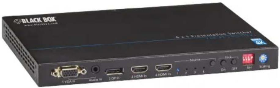
The Presentation Switcher - HDBaseT, 4 x 1 is an advanced four-input, multi-format converter, switcher, scaler, and extender with built-in 4K scaling, in a compact 1U half-rack enclosure. It offers two HDMI inputs, one DP input, one VGA input with stereo audio, an HDMI with HDBaseT mirrored output to allow signal extension over CATx cable to reach a remote display, or an additional HDBaseT signal management system. One balanced stereo audio breaks out from HDMI output.
NOTE: Scaling is only supported on HDMI output. For scaling on HDBaseT output, please use with VX-1003-TX scaling receiver.
The Switcher supports auto switching and has a built-in 4K @ 30 Hz scaler in HDMI output, with rotary switch scaler adjustment, and allows seamless switching to enhance presentations. Its built-in CEC controller automatically turns the display on/standby by auto-detecting the input signal status. You can also control the Switcher via pushbuttons on the front panel, contact closures, and RS-232 API.
The Switcher simplifies classroom and small office system integration, for installation beneath conference tables and in lecterns, to provide localized presentation switching support.
2.2 Features
- Has (1) VGA + Stereo, (1) DP, and (2) HDMI inputs, and (1) HDMI and (1) HDBaseT mirrored outputs.
- Supports HDMI and DP input up to 4K @ 30 Hz and HDCP 1.4, and VGA input up to 1920 x 1200 @ 60 Hz.
- Provides HDMI out with a 4K @ 30 Hz scaler built-in and de-embedded balanced stereo audio out.
- Mirrors out HDBaseT, and supports PoH with PSE module to power the remote HDBaseT receiver.
- HDMI out supports seamless and fast switching within 2–3 seconds, and the last frame is frozen.
-
Switches automatically to the latest input when it detects that any input is connected or disconnected.
-
A CEC controller is built-in to turn the display on/off by auto-detecting inputs status, with delay adjustment.
- Pushbuttons and contact closures enable you to switch sources or turn the display on/standby manually.
- DIP switch provided to adjust automatic or manual operation mode.
- Rotary switch provided to adjust auto-scaler or fixed resolutions out.
- Control the device via RS-232 and front panel buttons.
- Includes complete API commands for the third-party control system for integration.
- A 12-VDC, 3-A universal power supply powers the switcher.
- 1/2 rack unit high.
2.3 What's Included
Your package should contain the following items. If anything is missing or damaged, contact Black Box Technical Support at 724-746-5500 or info@blackbox.com.
- Presentation Switcher - HDBaseT, 4 x 1 (AVSC-0401H)
• (1) 12-DC, 3-A power adapter.
• (3) Phoenix male connector (3.5 mm, 3 pins)
• (3) Phoenix Male Connector (3.5 mm, 5 pins)
• (1) pair of mounting brackets - This user manual
2.4 Hardware Description
Figures 2-1 and 2-2 show the front and back panels of the switcher. Tables 2-1 and 2-2 describe their components.

Figure 2-1. Front panel.
Table 2-1. Front-panel components.
| Number in Figure 2-1 | Name Description | |
| 1 VGA IN Connects to VGA source device. | ||
| 2 Audio IN Stereo audio (embedded with VGA inputs). | ||
| 3 DisplayPort IN Connects to DisplayPort source device. | ||
| 4 HDMI IN Connects to HDMI source device. | ||
| 5 Source Selection LEDs | LED: Lights on if the corresponding source is selected. | |
| 6 Source Selection Button | Selection button: press the button to select source 1 to 4 as input in turn. | |
| 7 Sink Selection Button | On: Turn on the TV by CEC.Off: Turn off the TV by CEC.NOTE: Used for TV that supports CEC | |
| 8 | 4-Pin DIP switch | Pin 1: Audio De-embedded;Pin 2: Source Switch;Pin 3: CEC Control Mode;Pin 4: Control Mode |
| 9 Scaler Toggles the switch to manage the output scaler. | ||

Figure 2-2. Back panel.
Table 2-2. Back panel components.
| Number in Figure 2-2 | Component Description | |
| 1 Ethernet port | Used for Ethernet | passthrough to an HDBaseT receiver. |
| 2 RS-232 | passthrough | Connects to an RS-232 controller or RS-232 controllable device to pass through an RS-232 command. |
| 3 HDBaseT OUT port | Connects to an HDBaseT receiver. | |
| 4 HDMI OUT | port Connects to an | HDMI display device. |
| 5 AUDIO OUT | Ports Connects to an | an audio output device such as an amplifier, a speaker ,or an earphone for HDMI audio de-embedding output. |
| 6 Contact IN ports | Connects to a keypad for input source switching. | |
| 7 Tally OUT ports | Connects to LEDs on the keypad to indicate the selected source. | |
| 8 Sink ports | Connects to keypad to control the display device power ON/OFF. | |
| 9 | RS-232 control | Connects to a PC or a third-party control system to control this device via API commands. |
| 10 | Power input | Connect to a 12 VDC, 3-A power supply. |
2.5 Typical Application
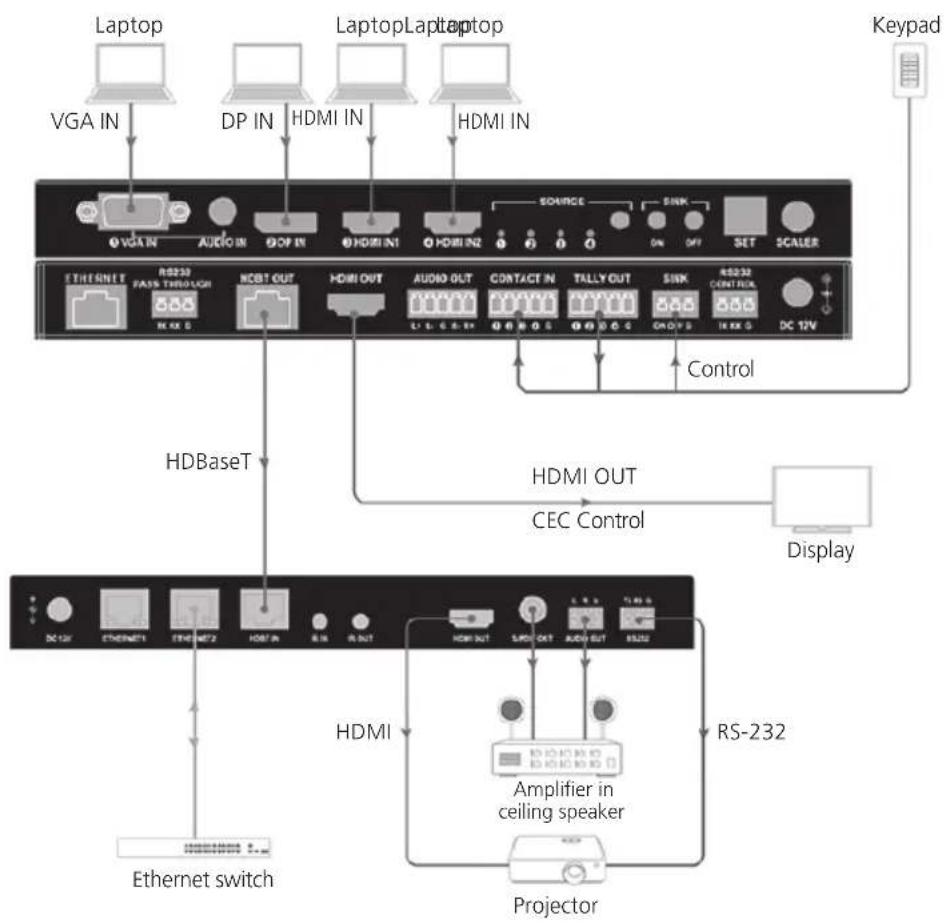
flowchart
graph TD
    A["Laptop"] --> B["VGA IN"]
    C["HPDA"] --> D["DP IN"]
    E["LaptopLap"] --> F["HDMI IN"]
    G["Keypad"] --> H["DC 12V"]
    I["HDBaseT"] --> J["HDBIN"]
    K["HDMI OUT"] --> L["CONTACT IN"]
    M["TCALL OUT"] --> N["SINK"]
    O["RS232"] --> P["Amplifier in ceiling speaker"]
    Q["Display"] --> R["Projector"]
    S["HDMI OUT"] --> T["CEC Control"]
    U["Ethernet switch"] --> V["PCB"]
    W["Source"] --> X["ON"]
    Y["SINK"] --> Z["OFF"]
    AA["SET"] --> AB["SCALER"]
    AC["Control"] --> AD["Data Bus"]
Figure 2-3. System Diagram.
3. RS-232 Connection
- Connect the matrix to a PC via a UART-to-USB cable.
- Run the UART tool on the PC, and configure the serial port as described in the following table.
Table 3-1. Serial port settings.
| Serial Parameter Setting | |
| Baud rate 57600 bps | |
| Data bits 8 bits | |
| Parity bits None | |
| Stop bits 1 bit | |
| Flow Control None | |
NOTE: The data format is ASCII.
3.1 API Commands
| IDX | Function | Command | Response | Parameters Desription | Example |
| 1 Set | API command ON/OFF | SET API_ONOFF prm[CR/LF] | API Mode: prm[CR/LF] | prm = {on,off} Command: SET API_ONOFF on [CR/LF]Response: API Mode: on [CR/LF] | |
| 2 Get | API Status GET API_STATUS[CR/LF] | STATUS[CR/LF] | API Mode: prm[CR/LF] | prm = {on,off} Command: GET API_STATUS[CR/LF]Response: API Mode: on [CR/LF] | |
| 3 Set | Auto Switch on/off | SET AUTOSW_ONOFF prm [CR/LF] | Auto Switch: prm [CR/LF] | prm = {on,off} Command: SET AUTOSW_ONOFF on [CR/LF]Response: Auto Switch: on [CR/LF] | |
| 4 Set | Auto Switch Mode | SET AUTOSW_MODE prm [CR/LF] | Auto Switch: prm [CR/LF] | prm = {on,off} Command: SET AUTOSW_ONOFF on [CR/LF]Response: Auto Switch: on [CR/LF] | |
| 5 Switch | to Next Source | SET SW_NEXT[CR/LF] | Source Select: prm[CR/LF] | prm = {vga,dp,hdmi1,hdmi2} | Command: SET SW_NEXT[CR/LF]Return: Source Select: DP[CR/LF] |
| 6 Switch | Input for Output | SET SW prm[CR/LF] | Source Select: prm[CR/LF] | SW is short for Swtichprm= {vga,dp,hdmi1,hdmi2} | Command: SET SW dp[CR/LF]Response: Source Select: dp[CR/LF] |
| 7 Get | Channel Switch State | GET SW_STATUS[CR/LF] | Source Select: prm1[CR/LF]Switch Mode: prm2[CR/LF] | prm1 = {vga,dp,hdmi1,hdmi2}prm2={Manual Mode,Automatic(Last Connected)Mode, Automatic(priority) Mode} | Command: GET SW_STATUS[CR/LF]Response: Source Select: dp[CR/LF]Switch Mode: Manual Mode[CR/LF]Description: prm1 = {vga,dp,hdmi1,hdmi2}prm2={Manual Mode,Automatic(Last Connected) Mode,Automatic(priority) Mode} |
| 8 Set | CEC functio SET | CECCMD_ONOFF prm[CR/LF] | CEC: prm[CR/LF] | prm = {on, off} | Command: SET CECCMD_ONOFF on[CR/LF]Response: CEC: on[CR/LF] |
| 9 Set | CEC AUTO POWER ON/OFF | SET CECAUTO_ONOFF prm[CR/LF] | Auto CEC: prm[CR/LF] | prm = {on, off} Command: SET CECAUTO_ONOFF on[CR/LF]Response: Auto CEC: on[CR/LF] | AUTO_ONOFF on[CR/LF]Response: Auto CEC: on[CR/LF] |
| 10 Set | CEC POWER Delay Time | SET CECAUTO_DELAY prm[CR/LF] | Auto CEC Delay Value: prm Min[CR/LF] | CECAUTO_DELAY is short for CEC auto Power Delay Timingprm = {0,1,2,3...}// according to the actual time counter, 1 means 1 minute, 2 means 2 minutesDefault wait time is 2 minutes off means when no active signal, the unit will not auto power off.0 means when no active signal, the unit auto power off immediately. | Command: SET CECAUTO_DELAY 3[CR/LF]Response: CECAUTO_DELAY 3 Min[CR/LF] |
| 11 Set | CEC POWER ON/OFF | SET CECPWR_ONOFF prm[CR/LF] | Send CEC cmd:HDMI TV prm[CR/LF]Send CEC cmd:HDBaseT TVprm[CR/LF] | CECPWR_ONOFF will control sink power on or offprm = {on, off} | Command: SET CECPWR_ONOFF on[CR/LF]Response: Send CEC cmd: HDMI TV OFF[CR/LF]Send CEC cmd: HDBaseT TV OFF[CR/LF] |
| 12 Get | CEC Status GET CEC_STATUS[CR/LF] | CEC: prm1[CR/LF]Auto CEC: prm1[CR/LF]Auto CEC DelayValue: prm2 Min[CR/LF] | prm1 = {on, off}prm2= {0-100} | Command: GET CEC_STATUS[CR/LF]Response: CEC: ON[CR/LF]Auto CEC: ON[CR/LF]Auto CEC Delay Value: 2 Min [CR/LF] | |
| 13 Set | Input HDCP Support ON/OFF | SET HDCPSUPPORT_ONOFF in prm1[CR/LF] | in: HDCP Supported[CR/LF] | in = {hdmi1, hdmi2, dp}prm1 = {on, off} | Command: SET HDCPSUPPORT_ONOFF hdmi1 on[CR/LF]Response: HDMI1:HDCP Supported[CR/LF] |
| 14 Get | Status Whether HDMI1/HDMI2 Input Support HDCP Info. | GET HDCP_STATUS[CR/LF] | in:prm1[CR/LF]in:prm1[CR/LF]HDMI OUT HDCPStatus: prm2[CR/LF] | in={hdmi1, hdmi2}prm1 = {HDCP Supported, HDCP Not supported}prm2={Non Encryption, Encryption} | Command: GET HDCP_STATUS[CR/LF]Response: HDMI1:HDCP Supported[CR/LF]HDMI2:HDCP Supported[CR/LF]HDMI OUT HDCP Status: Non Encryption[CR/LF] |
| 15 Set | Input EDID SET EDID in prm[CR/LF] | in EDID: prm[CR/LF] in = {vga,dp,hdmi1,hdmi2}; VGA:prm={fix0, fix1, fix2, fix3, fix4}fix0: 1280x800@60Hzfix1: 1920x1200@60Hzfix2: 1920x1080@60Hzfix3: 1280x720@60Hzfix4: 1024x768@60HzDP/HDMI1/HDMI2:prm={fix0, fix1, fix2, fix3, fix4, fix5, fix6, fix7}fix0: copyfix1: 4K@30Hz 2CHfix2: 1920x108060Hzfix3: 1280x720@60Hzfix4: 1920x1200@60Hzfix5: 1280x800@60Hzfix6: 1920x1080@60Hz Dolby 5.1 | Command: SET EDID hdmi1 fix1[CR/LF]Response: hdmi1 EDID: fix1[CR/LF] | ||
| 16 Get | Input EDID Status | GET EDID_STATUS[CR/LF] | VGA EDID:prm[CR/LF]DP EDID:prm[CR/LF]HDMI1 EDID:prm[CR/LF]HDMI2 EDID:prm[CR/LF] | VGA:prm={fix0, fix1, fix2, fix3, fix4}fix0: 1280x800@60Hzfix1: 1920x1200@60Hzfix2: 1920x1080@60Hzfix3: 1280x720@60Hzfix4: 1024x768@60HzDP/HDMI1/HDMI2:prm={fix0, fix1, fix2, fix3, fix4, fix5, fix6, fix7}fix0: copyfix1: 4K@30Hz 2CHfix2: 1920x108060Hzfix3: 1280x720@60Hzfix4: 1920x1200@60Hzfix5: 1280x800@60Hzfix6: 1920x1080@60Hz Dolby 5.1 | Command: GET EDID_STATUS[CR/LF]Response:VGA EDID: fix0[CR/LF]DP EDID: fix2[CR/LF]HDMI1 EDID: fix2[CR/LF]HDMI2 EDID: fix2[CR/LF] |
| 17 Volume Gain Adjust | SET VOLGAIN_DATA aout prm[CR/LF] | VOLGAIN_DATA aout prm[CR/LF] | VOLGAIN is volgainaout = {audiout};prm = {0~100 | Command: SET VOLGAIN_DATA audioout 50[CR/LF]Response: VOLGAIN_DATA audioout 50[CR/LF] | |
| 18 Audio Mute cmd SET MUTE aoutprm[CR/LF] | MUTE aout prm[CR/LF] | aout = {audiout};prm = {on, off}// on means mute;off means not audio mute | Command: SET MUTE audioout on [CR/LF]Response: MUTE audioout on [CR/LF] | ||
| 19 Set | Output Resolution | SET RESOLUTION out prm[CR/LF] | RESOLUTION out prm[CR/LF] | prm = {3840x2160@30, 1920x1200@60, 1920x1080@60, 1600x1200@60, 1366x768@60, 1280x1024@60, 1280x720@60, 1280x800@60, 1024x768@60, auto}out = {hdmout}; | Command: SET RESOLUTION hdmout auto[CR/LF]Response: RESOLUTION hdmout auto[CR/LF] |
| 20 Set | Standby on/off | SET STANDBY_ONOFF prm[CR/LF] | STANDBY_ONOFFprmCR/LF] | prm = {on, off} Command: SET STANDBY_ONOFF on[CR/LF]Response: STANDBY_ONOFF on [CR/LF] | |
| 21 Get | Scaler Mode Status | GET SCALER_STATUS[CR/LF] | Scaler Info:STANDBY_statusprm1[CR/LF]RESOLUTIONhdmout prm2[CR/LF]HDCP hdmoutprm1[CR/LF]MUTE audiooutprm1[CR/LF]VOLGAIN_DATAaudioout prm3[CR/LF] | prm1 = {on, off}prm2={3840x2160@30, 1920x1200@60, 1920x1080@60, 1600x1200@60, 1366x768@60, 1280x1024@60, 1280x720@60, 128Ox800@60, 1024x768@60, auto}prm3={0-100} | Command: GET SCALER_STATUS[CR/LF]Response: Scaler Info:STANDBY_status off[CR/LF]RESOLUTION hdmout auto[CR/LF]HDCP hdmout on[CR/LF]MUTE audioout off[CR/LF]VOLGAIN_DATA audioout 35[CR/LF] |
| 22 | Factory Reset | RESET[CR/LF] | / | / | Command: RESET[CR/LF] |
| 23 | System Reboot | REBOOT[CR/LF] | / | / | Command: REBOOT[CR/LF |
| 24 Get | System Status | GET SYS_STATUS[CR/LF] | Response all system status information | / Command: GET SYS_STATUS[CR/LF] | Response:...Response all system status information |
| 25 | Upgrade Module | UPG[CR/LF] | Enter ICP Mode...[CR/LF] | / Command: UPG CR/LF] | Response: Enter ICP Mode.....[CR/LF] |
3.2 Auto Mode
Auto Mode 1 (priority mode): VGA->DP->HDMI1->HDMI2
- When you power on the switcher, it defaults to the VGA channel if no source is active or connected. If some sources are already connected and then you power on the switcher, it will detect their priority and auto switch to the active source with the highest priority.
- When you connect a new source after power on, the switcher might automatically switch, depending on the priority. It will auto-switch to the new source if that source has higher priority than currently selected source, otherwise, it will not auto-switch.
- When the currently selected source is removed, the switcher might auto-switch, depending on the status of other sources connected and their priority. It will auto switch to the source active with highest priority, or remain on the current input channel if no source is active.
- Manual switching is also valid in Priority Mode. Press the button on the front panel to switch among active sources. You can manually switch via contact closures or API commands, depending on the source status. The unit will switch if the source manually selected is active, otherwise, an LED indicator will flash twice to indicate that a source is not active and does not switch the source.
Auto Mode 2 (Last Connected):
- When you power on the switcher, the VGA channel remains the default if no source is active or connected. If some sources are already connected and then you power on the switcher, it will detect their priority and auto switch to the active source with the highest priority.
- When you connect a new source after power on, the switcher will detect and auto-switch to this source.
- When you remove a currently selected source, the switcher might automatically connect to a source, depending on the status of other sources connected and their priority. It will auto switch to the source active with highest priority, or remain connected to the current input channel if no source is active.
- Manual switching is also valid in Priority Mode. Press the front-panel button on the front panel to switch among active sources. You can manually switch between sources via contact closures or API commands depending on the source status. It will switch if the source manually selected is active, otherwise, the LED indicator will flash twice to indicate the source is not active and does not switch.
4. Set and Scaler
4.1 Set

Figure 4-1. 4-Pin DIP switch.
Table 4-1. DIP switch settings.
| DIP Switch Position | Function Settings | |
| Pin 1 Audio de-embedded | UP: Audio out de-embedded from HDMI output (Default). DOWN: Reserved. | |
| Pin 2 Source | Switch Mode | UP: Enable Auto-Switch and Manual Switch (Default)DOWN: Manual Switch only. |
| Pin 3 CEC Control UP: Enable Auto-CEC Control and Manual CEC Control (Default)DOWN: Manual CEC Control only | ||
| Pin 4 | Control Mode | UP: Enable API control and manual control (Default).DOWN: Manual Control only. |
4.2 Scaler
HDMI output supports scaler output.

Figure 4-2. Rotary switch.
Table 4-2. Rotar y switch settings.
| Position Function |
| 0 Auto Scaler |
| 1 Select 1024 x 768 @ 60 Hz as native video. |
| 2 Select 1280 x 720 @ 60 Hz as native video. |
| 3 Select 1280 x 800 @ 60 Hz as native video. |
| 4 Select 1366 x 768 @ 60 Hz as native video. |
| 5 Select 1600 x 1200 @ 60 Hz as native video. |
| 6 Select 1920 x 1080 @ 60 Hz as native video. |
| 7 Select 1920 x 1200 @ 60 Hz as native video. |
| 8 Select 3840 x 2160 @ 30 Hz as native video. |
| 9 API Control |
Black Box Tech Support: FREE! Live. 24/7.
Tech support the way it should be.

natural_image
Close-up portrait of a smiling man holding a headset (no text or symbols visible)Great tech support is just 60 seconds away at 724-746-5500 or blackbox.com.

BLACK BOX®
About Black Box
Black Box provides an extensive range of networking and infrastructure products. You'll find everything from cabinets and racks and power and surge protection products to media converters and Ethernet switches all supported by free, live 24/7 Tech support available in 60 seconds or less.
© Copyright 2016. Black Box Corporation. All rights reserved. Black Box® and the Double Diamond logo are registered trademarks of BB Technologies, Inc. Any third-party trademarks appearing in this manual are acknowledged to be the property of their respective owners.
avsc-0401h_user_rev1
- Disclaimer
- FEDERAL COMMUNICATIONS COMMISSION AND INDUSTRY CANADA RADIO FREQUENCY INTERFERENCE STATEMENTS
- Table of Contents
- Overview
- Introduction
- Features
- What's Included
- Hardware Description
- Typical Application
- RS-232 Connection
- API Commands
- Auto Mode
- Auto Mode 2 (Last Connected):
- Set and Scaler
- Set
- Scaler
- BLACK BOX®
- About Black Box
Brand : Black Box
Model : AVSC-0401H
Category : Video switch