
QD-84 - Screen AG Neovo - Free user manual and instructions
Find the device manual for free QD-84 AG Neovo in PDF.


User questions about QD-84 AG Neovo
0 question about this device. Answer the ones you know or ask your own.
Ask a new question about this device
Download the instructions for your Screen in PDF format for free! Find your manual QD-84 - AG Neovo and take your electronic device back in hand. On this page are published all the documents necessary for the use of your device. QD-84 by AG Neovo.
USER MANUAL QD-84 AG Neovo
SAFETY INFORMATION ....1
REGULATORY INFORMATION......4
POLISH CENTER FOR TESTING AND CERTIFICATION NOTICE....5
CHAPTER 1: UNPACKING AND INSTALLATION....10
1.1. Unpacking.... 10
1.2. Package Contents ...... 10
1.3. Installation Notes 10
1.4. Mounting on a Wall 11
1.4.1. VESA Grid.... 12
1.5. Using of remote sensor and power indicator 12
CHAPTER 2: PARTS AND FUNCTIONS ...... 13
2.1. Control Panel 13
2.2. Input/Output Terminals.... 14
2.3. Remote Control....15
2.3.1 General functions 15
2.3.2 Inserting the batteries in the remote control 16
2.3.3 Handling the remote control 16
2.3.4 Operating range of the remote control.... 16
CHAPTER 3: CONNECTING EXTERNAL EQUIPMENT ...... 17
3.1 Connecting External Equipment (DVD/VCR/VCD) 17
3.1.1 Using COMPONENT video input.... 17
3.1.2 Using Video Source input 17
3.1.3. Using HDMI video input.... 17
3.2 Connecting a PC....18
3.2.1. Using VGA input 18
3.2.2. Using DVI input.... 18
3.2.3. Using HDMI input....18
3.2.4. Using DisplayPort input 19
3.3. Connecting Audio Equipment 19
3.3.1. Connecting external speakers....19
3.3.2. Connecting an external audio device 19
3.4. Connecting Multiple Displays in a Daisy-chain Configuration....20
3.4.1. Display control connection....20
3.4.2. Digital video connection....20
3.5. IR connection....21
3.6. IR Pass-through Connection....21
3.7. Wire-connecting to Network....21
CHAPTER 4: OPERATION....22
4.1. Watch the connected video source....22
4.2. Play multimedia files from USB device 22
TABLE OF CONTENTS
4.3. Play options 23
4.3.1. Playing music files 23
4.3.2. Playing movie files....23
4.3.3. Playing photo files 23
CHAPTER 5: OSD MENU....24
5.1. Navigating the OSD Menu 24
5.1.1. Navigating the OSD menu using the remote control 24
5.1.2. Navigating the OSD menu using the display's control buttons....25
5.2. OSD Menu Overview 25
5.2.1. Picture menu....25
5.2.2. Screen menu 26
5.2.3. Audio menu 28
5.2.4. PIP menu 29
5.2.5. Configuration1 menu 30
5.2.6. Configuration2 menu 33
5.2.7. Advanced option menu 34
5.2.8. Input menu....39
CHAPTER 6: USB DEVICE COMPATIBILITY....41
CHAPTER 7: INPUT MODE 44
CHAPTER 8: PIXEL DEFECT POLOGY....46
8.1. Pixels and Sub-Pixels 46
8.2. Types of Pixel Defects + Dot Definition....46
8.3. Bright Dot Defects....46
8.4. Dark Dot Defects 47
8.5. Proximity of Pixel Defects 47
8.6. Pixel Defect Tolerances 47
8.7. MURA 48
CHAPTER 9: CLEANING AND TROUBLESHOOTING....49
9.1. Cleaning....49
9.2. Troubleshooting 50
CHAPTER 10: TECHNICAL SPECIFICATIONS ....51
10.1. QD-84 & QD-98 51
Safety precautions and maintenance

WARNING: Use of controls, adjustments or procedures other than those specified in this documentation may result in exposure to shock, electrical hazards and/or mechanical hazards.
Read and follow these instructions when connecting and using your display:
Operation:
- Keep the display out of direct sunlight and away from stoves or any other heat sources.
- Remove any object that could fall into ventilation holes or prevent proper cooling of the display's electronics.
- Do not block the ventilation holes on the cabinet.
- When positioning the display, make sure the power plug and outlet are easily accessible.
- When turning off the display by detaching the power cord, wait 6 seconds before re-attaching the power cord for normal operation.
- Ensure the use of an approved power cord at all times. If your power cord is missing, please contact your local service center.
- Do not subject the display to severe vibration or high impact conditions during operation.
- Do not knock or drop the display during operation or transportation.
- The eye bolt is for usage in short-time maintenance and installation. We suggest not to use the eye bolt for more than 1 hour. Prolong usage is prohibited. Please keep a clear safety area under the display while using the eye bolt.
Maintenance:
- To protect your display from possible damage, do not put excessive pressure on the LCD panel. When moving your display, grasp the frame to lift; do not lift the display by placing your hand or fingers on the LCD panel.
- Unplug the display if you are not going to use it for an extensive period of time.
- Unplug the display if you need to clean it with a slightly damp cloth. The screen may be wiped with a dry cloth when the power is off. However, never use organic solvent, such as, alcohol, or ammonia-based liquids to clean your display.
- To avoid the risk of shock or permanent damage to the set, do not expose the display to dust, rain, water or an excessively moist environment.
- If your display becomes wet, wipe it with dry cloth as soon as possible.
- If a foreign substance or water gets in your display, turn the power off immediately and disconnect the power cord. Then remove the foreign substance or water, and send the unit to the maintenance center.
- Do not store or use the display in locations exposed to heat, direct sunlight or extreme cold.
- In order to maintain the best performance of your display and ensure a longer lifetime, we strongly recommend using the display in a location that falls within the following temperature and humidity ranges.
- Temperature: 0-40°C 32-104°F
- Humidity: 20-80% RH
IMPORTANT: Always activate a moving screen saver program when you leave your display unattended. Always activate a periodic screen refresh application if the unit will display unchanging static content. Uninterrupted display of still or static images over an extended period may cause "burn in", also known as "after-imaging" or "ghost imaging", on your screen. This is a well-known phenomenon in LCD panel technology. In most cases, the "burned in" or "after-imaging" or "ghost imaging" will disappear gradually over a period of time after the power has been switched off.
WARNING: Severe "burn-in" or "after-image" or "ghost image" symptoms will not disappear and cannot be repaired. This is also not covered under the terms of your warranty.
Service:
- The casing cover should be opened only by qualified service personnel.
- If there is any need for repair or integration, please contact your local service center.
- Do not leave your display under direct sunlight.

If your display does not operate normally, having followed the instructions set out in this document, please contact a technician or your local service center.
Read and follow these instructions when connecting and using your display:

- Unplug the display if you are not going to use it for an extensive period of time.
- Unplug the display if you need to clean it with a slightly damp cloth. The screen many be wiped with a dry cloth when the power is off. However, never use alcohol, solvents or ammonia-based liquids.
- Consult a service technician if the display does not operate normally when you have followed the instructions in this manual.
- The casing cover should be opened only by qualified service personnel.
- Keep the display out of direct sunlight and away from stoves or any other heat sources.
- Remove any object that could fall into the vents or prevent proper cooling of the display's electronics.
- Do not block the ventilation holes on the cabinet.
- Keep the display dry. To avoid electric shock, do not expose it to rain or excessive moisture.
- When turning off the display by detaching the power cable or DC power cord, wait for 6 seconds before re-attaching the power cable or DC power cord for normal operation..
- To avoid the risk of shock or permanent damage to the set do not expose the display to rain or excessive moisture.
- When positioning the display, make sure the power plug and outlet are easily accessible.
- IMPORTANT: Always activate a screen saver program during your application. If a still image in high contrast remains on the screen for an extended period of time, it may leave an ‘after-image’ or ‘ghost image’ on the front of the screen. This is a well-known phenomenon that is caused by the shortcomings inherent in LCD technology. In most cases the afterimage will disappear gradually over a period of time after the power has been switched off. Be aware that the after-image symptom cannot be repaired and is not covered under warranty.
EC Declaration of Conformity
We declare under our responsibility that the product is in conformity with the following standards:
- EN60950-1:2006+A11:2009+A1:2010+A12:2011+A2:2013 (Safety requirement of Information Technology Equipment).
- EN55022:2010 (Radio Disturbance requirement of Information Technology Equipment). This is Class A product. In a domestic environment this product may cause radio interference in which case the user may be required to take adequate measures. (Until 04 March, 2017)
• EN55024:2010 (Immunity requirement of Information Technology Equipment).
• EN61000-3-2:2006 +A1:2009+A2:2009 (Limits for Harmonic Current Emission).
• EN61000-3-3:2013 (Limitation of Voltage Fluctuation and Flicker) - EN 50581:2012 (Technical documentation for the assessment of electrical and electronic products with respect to the restriction of hazardous substances)
- EN 50564:2011 (Electrical and electronic household and office equipment — Measurement of low power consumption) following provisions of directives applicable.
• 2006/95/EC (Low Voltage Directive).
• 2004/108/EC (EMC Directive).
• 2009/125/EC (ErP, Energy-related Product Directive, EC No. 1275/2008 and 642/2009 Implementing) - 2011/65/EU (RoHS Directive) and is produced by a manufacturing organization on ISO9000 level.
- This equipment is compliant with Class A of EN55032/CISPR 32. In a residential environment this equipment may cause radio interference. (From 05 March, 2017)
Polish Center for Testing and Certification Notice
The equipment should draw power from a socket with an attached protection circuit (a three-prong socket). All equipment that works together (computer, display, printer, and so on) should have the same power supply source.
The phasing conductor of the room's electrical installation should have a reserve short-circuit protection device in the form of a fuse with a nominal value no larger than 16 amperes (A).
To completely switch off the equipment, the power supply cable must be removed from the power supply socket, which should be located near the equipment and easily accessible.
A protection mark "B" confirms that the equipment is in compliance with the protection usage requirements of standards PN-93/T-42107 and PN-89/E-06251.
Electric, Magnetic and Electromagnetic Fields ("EMF")
- We manufacture and sell many products targeted at consumers, which, like any electronic apparatus, in general have the ability to emit and receive electromagnetic signals.
- One of our leading Business Principles is to take all necessary health and safety measures for our products, to comply with all applicable legal requirements and to stay well within the EMF standards applicable at the time of producing the products.
- We are committed to develop, produce and market products that cause no adverse health effects.
- We confirm that if its products are handled properly for their intended use, they are safe to use according to scientific evidence available today.
- We play an active role in the development of international EMF and safety standards, enabling us to anticipate further developments in standardization for early integration in its products.
Information for U.K. only
text_image
(B) (A)WARNING - THIS APPLIANCE MUST BE EARTHED.
Important:
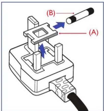
This apparatus is supplied with an approved moulded 13A plug. To change a fuse in this type of plug proceed as follows:
- Remove fuse cover and fuse.
- Fit new fuse which should be a BS 1362 5A,A.S.T.A. or BSI approved type.
- Refit the fuse cover.
If the fitted plug is not suitable for your socket outlets, it should be cut off and an appropriate 3-pin plug fitted in its place.
If the mains plug contains a fuse, this should have a value of 5A. If a plug without a fuse is used, the fuse at the distribution board should not be greater than 5A.
▲ NOTES: The severed plug must be destroyed to avoid a possible shock hazard should it be inserted into a 13A socket elsewhere.
natural_image
Diagram of a car electrical plug with colored wires (green, blue, red) showing internal components and connections (no text or labels)How to connect a plug
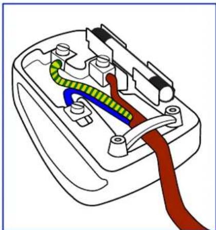
The wires in the mains lead are coloured in accordance with the following code:
BLUE - "NEUTRAL" ("N")
BROWN - "LIVE" ("L")
GREEN & YELLOW - "EARTH" ("E")
- The GREEN & YELLOW wire must be connected to the terminal in the plug which is marked with the letter "E" or by the Earth symbol or coloured GREEN or GREEN & YELLOW.
- The BLUE wire must be connected to the terminal which is marked with the letter "N" or coloured BLACK.
- The BROWN wire must be connected to the terminal which marked with the letter "L" or coloured RED.
Before replacing the plug cover, make certain that the cord grip is clamped over the sheath of the lead - not simply over the three wires.
SAFETY INSTRUCTIONS
North Europe (Nordic Countries) Information
Placering/Ventilation
VARNING: FÖRSÄKRA DIG OM ATT HUVUDBRYTARE OCH UTTAG ÄR LÄTÄTKOMLIGA, NÄR DU STÄLLER DIN UTRUSTNING PÅPLATS.
Placering/Ventilation
ADVARSEL: S∅RG VED PLACERINGEN FOR, AT NETLEDNINGENS STIK OG STIKKONTAKT ER NEMT TILGÆNGELIGE.
Paikka/Ilmankierto
VAROITUS: SIJOITA LAITE SITEN, ETTÄ VERKKOJOHTO VOIDAAAN TARVITTAESSA HELPOSTI IRROTTAA PISTORASIASTA.
End-of-Life Disposal
Your new Public Information Display contains materials that can be recycled and reused.
Specialized companies can recycle your product to increase the amount of reusable materials and to minimize the amount to be disposed of.
Please find out about the local regulations on how to dispose of your old display from your local dealer.
(For customers in Canada and U.S.A.)
This product may contain lead and/or mercury. Dispose of in accordance to local-state and federal regulations. For additional information on recycling contact www.eia.org (Consumer Education Initiative)
Waste Electrical and Electronie Equipment-WEEE
Attention users in European Union private households
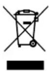
This marking on the product or on its packaging illustrates that, under European Directive 2012/19/EU governing used electrical and electronic appliances, this product may not be disposed of with normal household waste. You are responsible for disposal of this equipment through a designated waste electrical and electronic equipment collection. To determine the locations for dropping off such waste electrical and electronic, contact your local government office, the waste disposal organization that serves your household or the store at which you purchased the product.
Attention users in United States:
Please dispose of according to all Local, State and Federal Laws. For the disposal or recycling information, contact: www.mygreenelectronics.com or www.eiae.org.
End of Life Directives-Recycling

Your new Public Information Display contains several materials that can be recycled for new users.
Please dispose of according to all Local, State, and Federal laws.
Restriction on Hazardous Substances statement (India)
This product complies with the “India E-waste Rule 2016” and prohibits use of lead, mercury, hexavalent chromium, polybrominated biphenyls or polybrominated diphenyl ethers in concentrations exceeding 0.1 weight % and 0.01 weight % for cadmium, except for the exemptions set in Schedule 2 of the Rule.
E-Waste Declaration for India
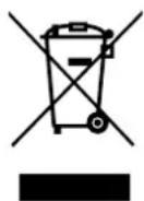
This symbol on the product or on its packaging indicates that this product must not be disposed of with your other household waste. Instead it is your responsibility to dispose of your waste equipment by handing it over to a designated collection point for the recycling of waste electrical and electronic equipment. The separate collection and recycling of your waste equipment at the time of disposal will help to conserve natural resources and ensure that it is recycled in a manner that protects human health and the environment.
Batteries
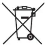
For EU: The crossed-out wheeled bin implies that used batteries should not be put to the general household waste! There is a separate collection system for used batteries, to allow proper treatment and recycling in accordance with legislation.
Please contact your local authority for details on the collection and recycling schemes.
For Switzerland: The used battery is to be returned to the selling point.
For other non-EU countries: Please contact your local authority for correct method of disposal of the used battery.
According to EU directive 2006/66/EC, the battery can't be disposed improperly. The battery shall be separated to collect by local service.
CHAPTER 1: UNPACKING AND INSTALLATION
1.1. Unpacking
- This product is packed in a carton, together with the standard accessories.
- Any other optional accessories will be packed separately.
- Due to the size and weight of this display it is recommended for two people to move it.
• After opening the carton, ensure that the contents are complete and in good condition.
1.2. Package Contents
Please verify that you received the following items with your package content:
- LCD display
- User manual
- Remote control with AAA batteries
• Power cord (1.8 m) - VGA cable (1.8 m)
• RS232 cable (3 m)
• Daisy Chain cable (3 m)
natural_image
Plain light blue gradient background with no text, symbols, or discernible objects* The supplied power cord varies depending on destination.
User Manual
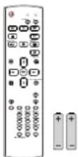
Remote Control and AAA Batteries
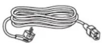
Power Cord
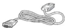
Video Signal Cable (D-SUB to D-SUB Cable)
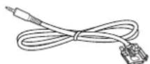
RS232 Cable
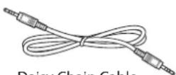
Daisy Chain Cable
NOTES:
- For all other regions, apply a power cord that conforms to the AC voltage of the power socket and has been approved by and complies with the safety regulations of the particular country.
- You might like to save the package box and packing material for shipping the display.
1.3. Installation Notes
- Due to the high power consumption, always use the plug exclusively designed for this product. If an extended line is required, please consult your service agent.
- The product should be installed on a flat surface to avoid tipping. The distance between the back of the product and the wall should be maintained for proper ventilation. Avoid installing the product in the kitchen, bathroom or any other places with high humidity so as not to shorten the service life of the electronic components.
- The product can normally operate only under 5000m in altitude. In installations at altitudes above 5000m, some abnormalities may be experienced.
1.4. Mounting on a Wall
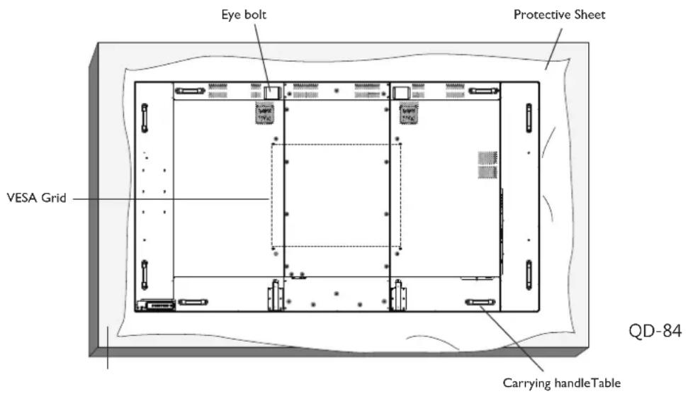
To mount this display to a wall, you will have to obtain a standard wall-mounting kit (commercially available). We recommend using a mounting interface that complies with TUV-GS and/or UL1678 standard in North America.
text_image
Eye bolt Protective Sheet VESA Grid QD-84 Carrying handleTable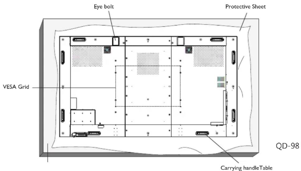
text_image
Eye bolt Protective Sheet VESA Grid QD-98 Carrying handleTable- Lay a protective sheet on a table, which was wrapped around the display when it was packaged, beneath the screen surface so it will not scratch the screen face.
- Ensure you have all the accessories for mounting this display (wall mount, ceiling mount, table stand, etc).
- Follow the instructions that come with the base mounting kit. Failure to follow correct mounting procedures could result in damage to the equipment or injury to the user or installer. Product warranty does not cover damage caused by improper installation.
- For the wall-mounting kit, use M8 mounting screws (having a length 15 mm longer than the thickness of the mounting bracket) and tighten them securely.
- The eye bolt is using for short-time maintenance and installation. We suggest not to use the eye bolt for more than 1 hour. Prolong the usage is prohibited. Please keep a clear safety area under the display while using the eye bolt.
- Mount the display on the wall when installing or maintaining the display only. It is not recommended to mount the display on the wall over one hour. It might cause damage on the display when mounting the display for a long time. When mounting the display, clear all other items under the display.
UNPACKING AND INSTALLATION
1.4.1. VESA Grid
| Model Name Vesa Grid | |
| QD-84 | 600(H) x 500(V) mm |
| QD-98 | 800(H) x 500(V) mm |
Caution:
To prevent the display from falling:
- For wall or ceiling installation, we recommend installing the display with metal brackets which are commercially available. For detailed installation instructions, refer to the guide received with the respective bracket.
- To lessen the probability of injury and damage of the display from earthquake or other natural disaster, be sure to consult the bracket manufacturer for installation location.
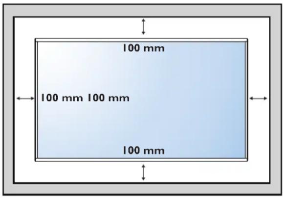
Ventilation Requirements for enclosure locating
To allow heat to disperse, leave space between surrounding objects as shown in the diagram below.
text_image
100 mm 100 mm 100 mm 100 mm1.5. Using of remote sensor and power indicator
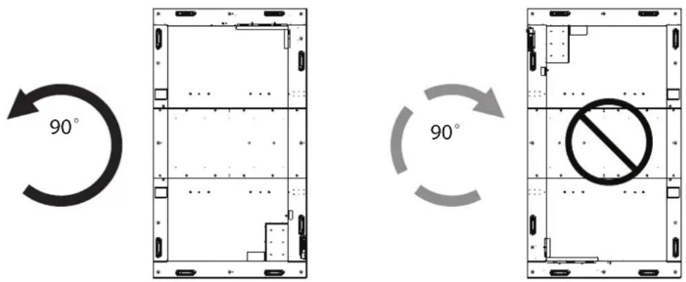
This display can be installed in portrait position.
When facing the display at the back, rotate 90 degrees anticlockwise, the input/output terminals should at the top and right side.
text_image
90° 90°▲ NOTES: When installing the display on a wall, please consult a professional technician for proper installation. We accept no liability for installations not performed by a professional technician.
CHAPTER 2: PARTS AND FUNCTIONS
2.1. Control Panel
text_image
Technical diagram of a server rack with labeled ports and control buttons, including MUTEINPUT and MENU indicators.① [button
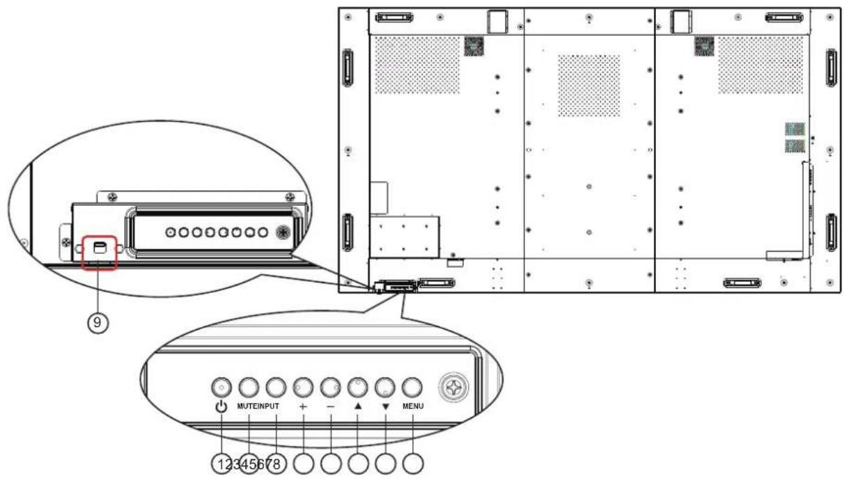
Use this button to turn the display on or put the display to standby.
② [MUTE] button
Switch the audio mute ON/OFF.
③ [INPUT] button
Use this button to select the input source.
④ [+] button
Increase the adjustment while OSD menu is on, or increase the audio output level while OSD menu is off.
• Used as [OK] button in the On-Screen-Display menu.
⑤ [+]button
Decrease the adjustment while OSD menu is on, or decrease the audio output level while OSD menu is off.
⑥ [▲button
Move the highlight bar up to adjust the selected item while OSD menu is on.
⑦ [▼button
Move the highlight bar down to adjust the selected item while OSD menu is on.
⑧ [MENU] button
Return to previous menu while OSD menu is on, or to activate the OSD menu when OSD menu is off.
⑨ Remote control sensor and power status indicator
- Receives command signals from the remote control.
-
Indicates the operating status of the display:
-
Lights green when the display is turned on.
- Lights red when the display is in standby mode.
- Lights amber when the display enters power save mode or deep sleep mode.
- When {SCHEDULE} is enabled, the light blinks green and red.
- If the light blinks red, it indicates that a failure has been detected.
- Lights off when the main power of the display is turned off.
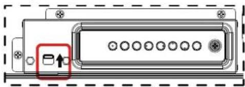
- Push up to hide the remote control sensor and power stauts indicator:
natural_image
Diagram of an electronic device rear panel with ports and a highlighted button (no text or symbols)2.2. Input/Output Terminals
text_image
Technical diagram of a server rack with labeled ports and internal components, including zoomed-in insets for details.① AC IN
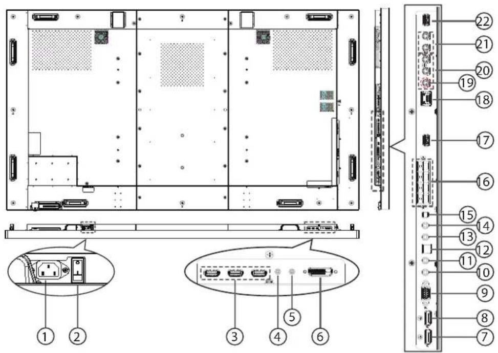
AC power input from the wall outlet.
② MAIN POWER SWITCH
Switch the main power on/off.
③ HDMI1 IN / HDMI2 IN / HDMI3 IN
HDMI video/audio input.
④ RS232C IN / ⑤ RS232C OUT
RS232C network input / output for the loop-through function.
⑥ DVI IN
DVI-D video input.
⑦ DisplayPort IN / ⑧ DisplayPort OUT
DisplayPort video input / output.
⑨ VGA IN (D-Sub)
VGA video input.
⑩ IR IN / ⑪ IR OUT
IR signal input / output for the loop-through function.
NOTE:
- This display's remote control sensor will stop working if the jack [IR IN] is connected.
- To remotely control your A/V device via this display, refer to page for IR Pass Through connection.
⑫ SPDIF OUT
Digital audio output
⑬ AUDIO IN
Audio input for VGA source (3.5mm stereo phone).
⑭ AUDIO OUT
Audio output to external AV device.
⑮ SPEAKER SWITCH
Internal speaker on/off switch.
⑯ SPEAKERS OUT
Audio output to external speakers.
⑰ USB SERVICE PORT
Connect to USB storage for main board Firmware update.
NOTE: It's for updating firmware only.
⑱ RJ-45
LAN control function for the use of remote control signal from control center.
⑲ Y/CVBS
Video source input.
⑳ COMPONENT IN
Component YPbPr video source input.
②1 AUDIO IN
Audio input from external AV device (RCA).
22 USB PORT
Connect your USB storage device
PARTS AND FUNCTIONS
2.3. Remote Control
2.3.1 General functions
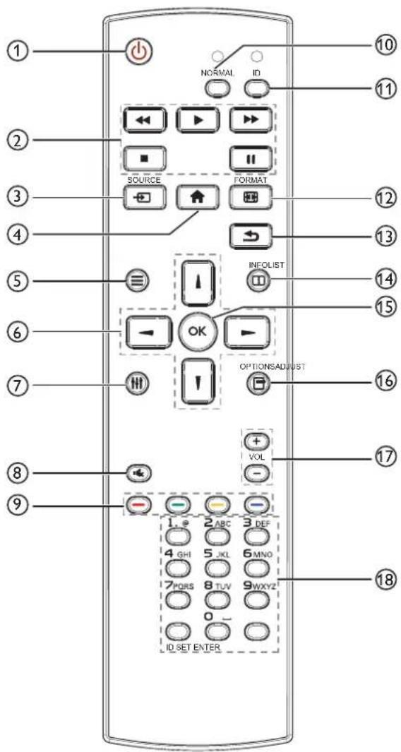
text_image
1 2 3 4 5 6 7 8 9 NORMAL ID SOURCE FORMAT INFOLIST OK OPTIONSADJUST VOL 1. 2 ABC 3 DEF 4 GHI 5 JKL 6 MNO 7 PORS 8 TUV 9WXYZ 0 ID SET ENTER 10 11 12 13 14 15 16 17 18① [POWER button]
Turn the display on or put the display to standby.
② [PLAY] buttons
Control playback of media files.
③ [→SOURCE button]
Choose input source. Press [1] or [1] button to choose from DisplayPort, DVI-D, VGA. HDMI 1, HDMI 2, HDMI 3, Component, Video, USB or Card OPS. Press [1] button to confirm and exit.
④ [HOME button
Access the OSD menu.
⑤ LIST button
No function.
⑥ [1] [1] [+][ ]-NAVIGATION buttons
Navigate through menus and choose items.
⑦ [↑]↑ADJUST button
To auto adjust for VGA input only.
⑧ [×] MUTE button
Press to turn the mute function on/off.
⑨ [—] [—] [—] [—] COLOR buttons
Choose tasks or options.
⑩ [NORMAL] buttons
Switch to normal mode.
⑪ [ID] buttons
Switch to ID mode.
⑫ [FORMAT button]
Change zoom mode.
⑬ [BACK button]
Return to the previous menu page or exit from the previous function.
⑭ [i] INFO button
Display information about current activity.
⑮ [OK] button
Confirm an entry or selection.
⑯ [OPTIONS button
Access currently available options, picture and sound menus.
⑰ [−] [+] VOLUME button
Adjust volume.
⑱ [NUMERIC] buttons
Enter text for network setting, and set up ID for ID mode.
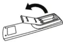
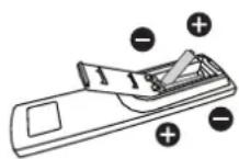
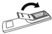
2.3.2 Inserting the batteries in the remote control
The remote control is powered by two 1.5V AAA batteries.
To install or replace batteries:
- Press and then slide the cover to open it.
- Align the batteries according to the (+) and (−) indications inside the battery compartment.
- Replace the cover.
Caution:
The incorrect use of batteries can result in leaks or bursting. Be sure to follow these instructions:
- Place “AAA” batteries matching the (+) and (−) signs on each battery to the (+) and (−) signs of the battery compartment.
- Do not mix battery types.
- Do not combine new batteries with used ones. It causes shorter life or leakage of batteries.
- Remove the dead batteries immediately to prevent them from liquid leaking in the battery compartment. Don't touch exposed battery acid, as it can damage your skin.
NOTE: If you do not intend to use the remote control for a long period, remove the batteries.
2.3.3 Handling the remote control
- Do not subject to strong shock.
- Do not allow water or other liquid to splash the remote control. If the remote control gets wet, wipe it dry immediately.
- Avoid exposure to heat and steam.
- Other than to install the batteries, do not open the remote control.
2.3.4 Operating range of the remote control
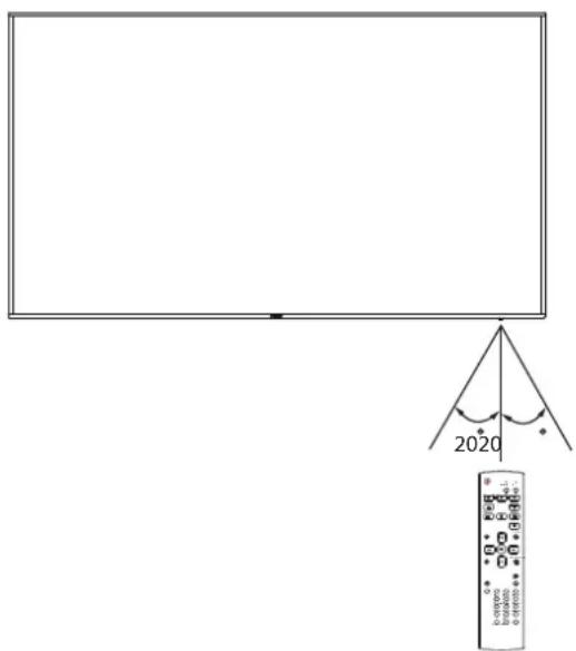
Point the front of the remote control toward this display's remote control sensor when pressing a button.
Use the remote control within a distance of less than 5m/16ft from this display's sensor, and a horizontal and vertical angle of less than 30 degrees.
▲ NOTE: The remote control may not function properly when the remote control sensor on this display is under direct sunlight or strong illumination, or when there is an obstacle in the path of signal transmission.
text_image
2020 k-00000 0.00000 0.00000CHAPTER 3: CONNECTING EXTERNAL EQUIPMENT
3.1 Connecting External Equipment (DVD/VCR/VCD)
3.1.1 Using COMPONENT video input

text_image
[AUDIO IN] [R] [L] [COMPONENT IN] (YPbPr) COMPONENT Out (YPbPr) Audio Out DVD / VCR / VCD3.1.2 Using Video Source input
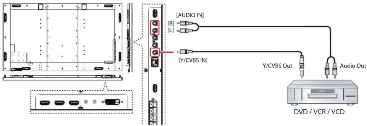
text_image
[AUDIO IN] [R] [L] [Y/CVBS IN] Y/CVBS Out Audio Out DVD / VCR / VCD3.1.3 Using HDMI video input
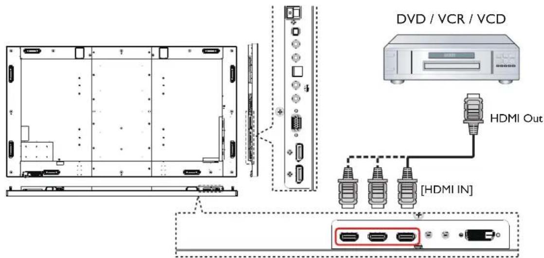
text_image
DVD / VCR / VCD HDMI Out [HDMI IN]3.2 Connecting a PC
3.2.1 Using VGA input

text_image
PC Audio Out [VGA AUDIO IN] VGA OUT D-Sub 15 pin [VGA IN]3.2.2 Using DVI input
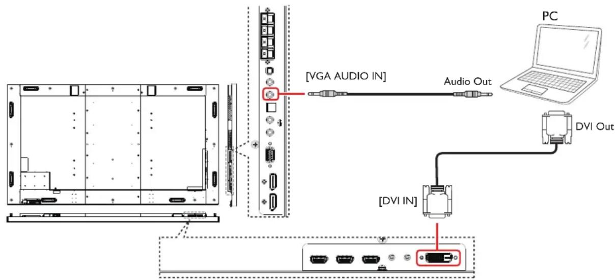
text_image
[VGA AUDIO IN] Audio Out PC DVI Out [DVI IN]3.2.3 Using HDMI input
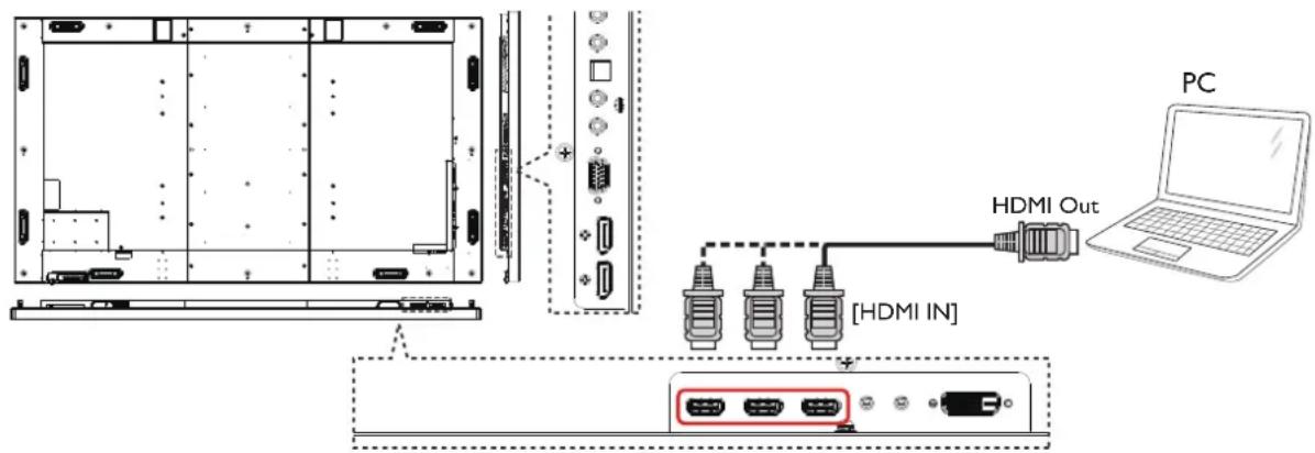
text_image
PC HDMI Out [HDMI IN]CONNECTING EXTERNAL EQUIPMENT
3.2.4 Using DisplayPort input
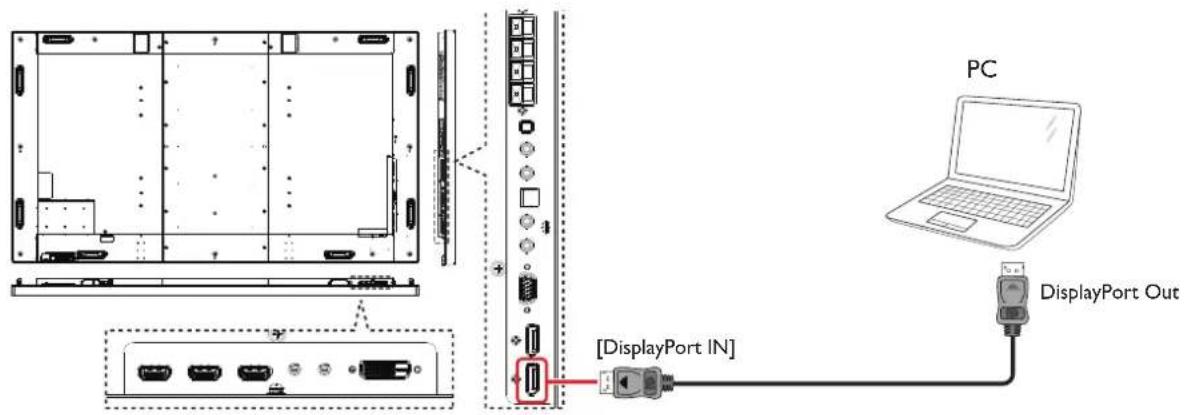
text_image
PC DisplayPort Out [DisplayPort IN]3.3 Connecting Audio Equipment
3.3.1 Connecting external speakers
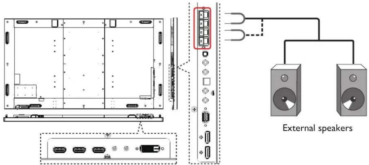
text_image
External speakers3.3.2 Connecting an external audio device
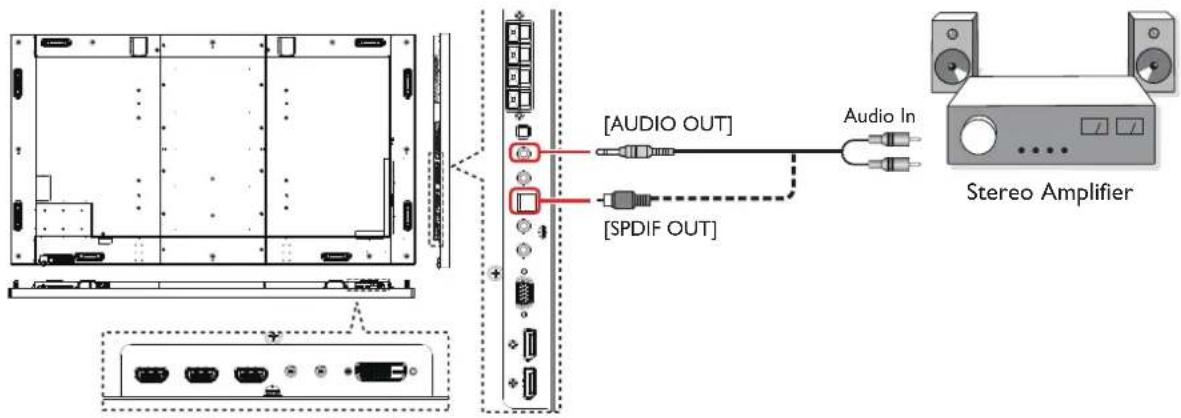
text_image
[AUDIO OUT] [SPDIF OUT] Audio In Stereo Amplifier3.4 Connecting Multiple Displays in a Daisy-chain Configuration
You can connect multiple displays to create a daisy-chain configuration for applications such as a video wall.
▲ NOTES: Maximum 25 displays (5x5) can be used in a daisy-chain configuration.
3.4.1 Display control connection
Connect the [RS232C OUT] connector of DISPLAY 1 to the [RS232C IN] connector of DISPLAY 2.
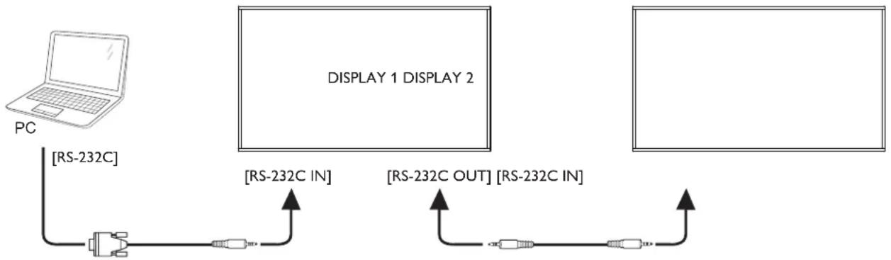
flowchart
graph LR
    PC["PC"] -->|[RS-232C]| A["Switch"]
    A --> B["Display 1 DISPLAY 2"]
    B --> C["Display 2"]
    C --> D["Output"]
    style PC fill:#f9f,stroke:#333
    style Display1 fill:#ccf,stroke:#333
    style Display2 fill:#ccf,stroke:#333
3.4.2 Digital video connection
Connect the [DP OUT] connector of DISPLAY 1 to the [DP IN] connector of DISPLAY 2.
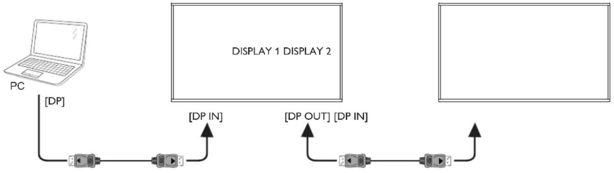
flowchart
graph TD
    PC["PC"] -->|[DP]| A["Device 1"]
    A -->|[DP IN]| B["Display 2"]
    B -->|[DP OUT] | C["Device 2"]
    C -->|[DP IN]| A
CONNECTING EXTERNAL EQUIPMENT
3.5 IR connection
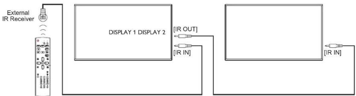
flowchart
graph LR
    A["External IR Receiver"] --> B["Display 1 DISPLAY 2"]
    B --> C["IR OUT"]
    B --> D["IR IN"]
    B --> E["IR IN"]
▲ NOTES: This display's remote control sensor will stop working if the [IR IN] is connected.
3.6 IR Pass-through Connection
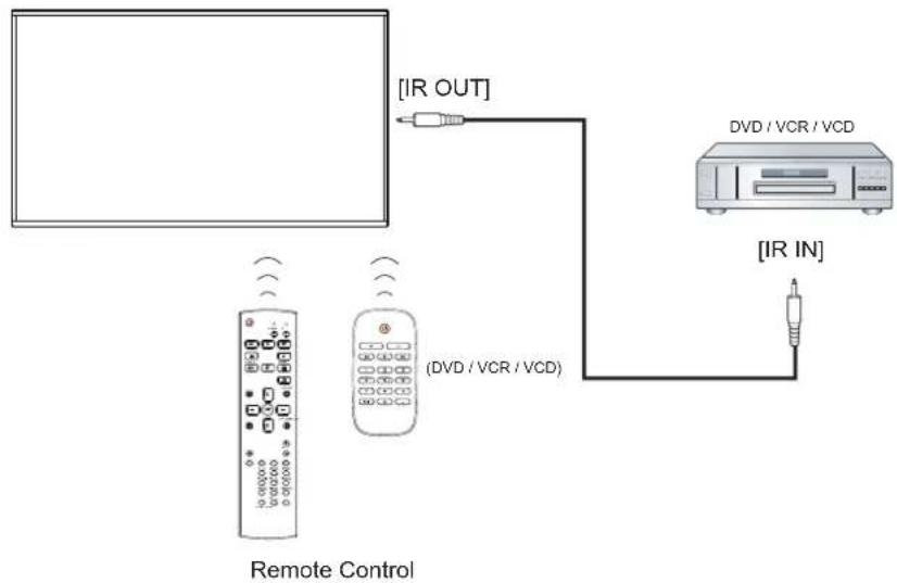
flowchart
graph TD
    A["Remote Control"] -->|IR OUT| B["DVD / VCR / VCD"]
    A -->|IR IN| C["IR IN"]
    B --> D["Computer"]
3.7 Wire-connecting to Network
If you connect this display to a home network, you can play photos, music and videos from your computer. See Play multimedia files via Local Area Network for more detail.
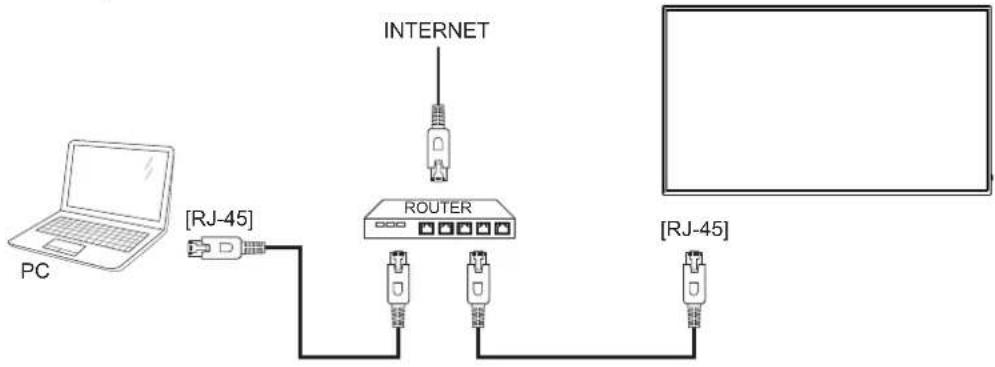
flowchart
graph TD
    PC["PC"] --> RJ45["RJ-45"]
    RJ45 --> ROUTER["ROUTER"]
    ROUTER --> INTERNET["INTERNET"]
    INTERNET --> ROUTER
    ROUTER --> RJ45["RJ-45"]
NOTE: The control button described in this section is mainly on the remote control unless specified otherwise.
4.1 Watch the connected video source
- Press [→SOURCE button.
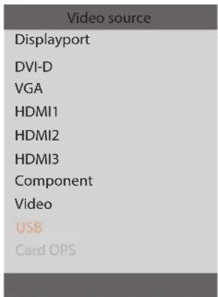
text_image
Video source Displayport DVI-D VGA HDMI1 HDMI2 HDMI3 Component Video USB Card OPS- Press [1] or [7] button to choose a device, then press [OK] button.
4.2 Play multimedia files from USB device
- Connect your USB device to the USB port on the display.
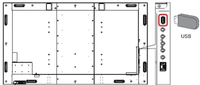
text_image
USB- Press [→] SOURCE button, choose USB, and press [OK] button.
- The connected USB device is detected automatically for all its playable files, which will be automatically sorted into 3 types: 🎨 Music, 📄 Movie, and 🌐 Photo.
- Press [→] BACK button to go up to the top layer in the screen. Press [→] or [→] button to choose the file type. Press [OK] button to enter its play list.
- Choose the file you want. Press [OK] button to start playing.
- Follow the on-screen instruction to control the play option.
- Press [PLAY] buttons (■ □ ◀◀ ▶ ▶▶) to control playing.
4.3 Play options
4.3.1 Playing music files
- Choose 🎶 Music in the top bar.

-
Choose one music track, and press [OK] button.
-
To play all the tracks in a folder, choose one music file. Then, press [—] to Play All.
- To skip to the next or previous track, press [1] or [7] button.
- To pause the track, press [OK] button. Press [OK] button again to resume playback.
- To skip backward or forward 10 seconds, press [→] or [→] button.
- To search backward or forward, press [◀◀] or [▶▶] button, press repeatedly to toggle between different speeds.
- To stop the music, press [■] button.
4.3.2 Playing movie files
- Choose □ Movie in the top bar.

-
Choose a video, and press [OK] button.
-
To play all the videos in a folder, choose one video file. Then, press [—] to Play All.
- To pause the video, press [OK] button. Press [OK] button again to resume playback.
- To skip backward or forward 10 seconds, press [→] or [→] button.
- To search backward or forward, press [◀◀] or [▶▶] button, press repeatedly to toggle between different speeds.
- To stop the video, press [■] button.
4.3.3 Playing photo files
- Choose 📄 Photo in the top bar.

- Choose a photo thumbnail, then press OK] button.
Start a slideshow
If there are multiple photos in a folder, choose a photo. Then, press
[—] to Play All.
- To skip to the previous or next photo, press [→] or [→] button, and then press [OK] button.
- To stop the slideshow, press [■] button.
An overall view of the On-Screen Display (OSD) structure is shown below. You can use it as a reference for further adjusting your display.
5.1 Navigating the OSD Menu
5.1.1 Navigating the OSD menu using the remote control
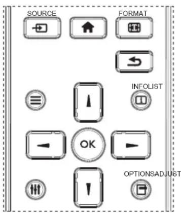
text_image
SOURCE FORMAT INFOLIST OK OPTIONSADJUST- Press [button on the remote control to display the OSD menu.
- Press [1] or [7] button to choose the item you want to adjust.
- Press [OK] or [▶] button to enter the submenu.
- In the submenu, press [1] or [1] button to toggle among items, press [—] or [—] button to adjust settings. If there is a submenu, press [OK] or [+button to enter the submenu.
- Press [→] button to return to the previous menu, or press [→] button to exit the OSD menu.
5.1.2 Navigating the OSD menu using the display's control buttons
- Press [MENU] button to display the OSD menu.
- Press [+] or [+] button to choose the item you want to adjust.
- Press [+] button to enter the submenu.
- In the submenu, press [▲] or [▼button to toggle among items, press [ ] or [ ] button to adjust settings. If there is a submenu, press [−button to enter the submenu.
- Press [MENU] button to return to the previous menu, or press [MENU] button several times to exit the OSD menu.
5.2 OSD Menu Overview
5.2.1 Picture menu
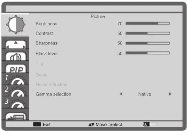
text_image
Picture Brightness 70 Contrast 50 Sharpness 50 Black level 50 Tint Color Noise reduction Gamma selection ← Native ► :Exit ▲:Move :Select SET/ENDBrightness
Adjust the overall image brightness by changing the intensity of the LCD panel's backlight.
Contrast
Adjust to sharpen the picture quality. The black portions of the picture become richer in darkness and the white become brighter.
Sharpness
Adjust to improve the image detail.
Black level
Video black level is defined as the level of brightness at the darkest (black) part of a visual image. Adjust to change the image brightness.
Tint
Adjust to change the color tint of the image.
Use the [→] or [→] button to adjust. Press the [→] button and the flesh tone color turns slightly green. Press the [→] button and the flesh tone color turns slightly purple.
NOTE: This item functional for Video mode(YUV color space) only.
Color
Adjust to increase or decrease the intensity of colors in the image.
NOTE: This item functional for Video mode(YUV color space) only.
Noise reduction
Adjust to remove the noise in the image. You can select a suitable noise reduction level.
Choose from: {Off} / {Low} / {Medium} / {High}.
▲ NOTES: This item functional for Video mode(YUV color space) only.
Gamma selection
Gamma is what controls the overall brightness of an image. Images which are not corrected properly can appear too white or too dark, so controlling the gamma properly can have a huge influence on the overall picture quality of your display.
The options are: {Native} / {2.2} / {2.4} / {S gamma}
Choose from: {3000K} / {4000K} / {5000K} / {6500K} / {7500K} / {9300K} / {10000K} / {Native} / {User}.
Color control
You can adjust the color tones of the image precisely by changing the User-R (Red), User-G (Green) and User-B (Blue) settings independently when the following condition:
{Picture} - {Color temperature} - {User}
Smart picture
The following smart picture modes are available for:
- PC mode: {Standard} / {Highbright} / {sRGB}.
• Video mode: {Standard} / {Highbright} / {Cinema}.
Light sensor
Light sensor function is to adjust brightness automatically when ambient light changed
Scan mode
Change the display area of the image.
- {Over scan} - Display about 95% of the original size of the image. The rest of the areas surrounding the image will be cut off.
- {Under scan} - Display the image in its original size.
Picture reset
Reset all settings in the Picture menu.
5.2.2 Screen menu
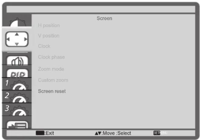
text_image
Screen H position V position Clock Clock phase Zoom mode Custom zoom Screen reset Exit Move:Select SET:NU.H position
Press the [▶] button to move the image to the right, or [◀] to move the image to the left.
NOTES:
- H position adjustment is functional for VGA input only.
- H position cannot be adjusted when Anti-Burn-in^TM is activated.
V position
Press the [ ] button to move the image up, or [ ] to move the image down.
NOTES:
• V position adjustment is functional for VGA input only.
- V position cannot be adjusted when Anti-Burn-in^TM is activated.
Clock
Adjust the width of the image.
▲ NOTES: This item is functional for VGA input only.
Clock phase
Adjust to improve the focus, clarity and stability of the image.
▲ NOTES: This item is functional for VGA input only.
Zoom mode
The pictures you receive may be transmitted in 16:9 format (wide screen) or 4:3 format (conventional screen). The 16:9 pictures sometimes have a black band at the top and bottom of the screen (letterbox format). Zoom Mode will be deactivated when {Anti-Burn-in™} is activated or turned on, and when {Tiling} is enabled.
Choose from: {Full} / {Normal} / {Real} / {21:9} / {Custom}.
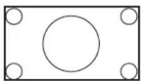 | FullThis mode restores the correct proportions of pictures transmitted in 16:9 using the full screen display. |
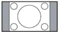 | NormalThe picture is reproduced in 4:3 format and a black band is displayed on either side of the picture. |
| RealThis mode displays the image pixel-by-pixel on screen without scaling the original image size. | |
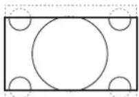 | 21:9The picture is enlarged to 21:9 format. This mode is recommended when displaying pictures that have black bands at the top and bottom (letterbox format). |
| CustomChoose to apply the custom zoom settings in the Custom Zoom submenu. |
Custom zoom
You can use this function to further customize the zoom settings to suit the image you want to display.
▲ NOTES: This item is functional only when the {Zoom mode} is set to {Custom}.
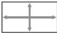
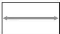
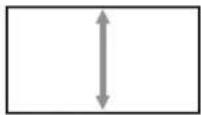
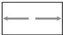
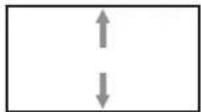
Zoom
Expands the horizontal and vertical sizes of the image simultaneously.
H zoom
Expands the horizontal size of the image only.
V zoom
Expands the vertical size of the image only.
H position
Moves the horizontal position of the image left or right.
V position
Moves the vertical position of the image up or down.
Screen reset
Reset all settings in the Screen menu to factory preset values.
5.2.3 Audio menu
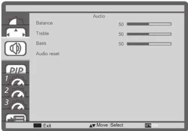
text_image
Audio Balance 50 Treble 50 Bass 50 Audio reset Exit Move Select SET/ENIBalance
Adjust to emphasize left or right audio output balance.
Treble
Adjust to increase or decrease higher-pitched sounds.
Bass
Adjust to increase or decrease lower-pitched sounds.
Audio reset
Reset all settings in the Audio menu to factory preset values.
5.2.4 PIP menu
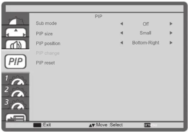
text_image
PIP Sub mode Off PIP size Small PIP position Bottom-Right PIP change PIP reset Exit Move :Select SET:NUSub mode
Select the PIP (Picture-in-Picture) mode.
Choose from: {Off} / {PIP} / {POP} / {Quick swap} / {PBP 2Win} / {PBP 3Win} / {PBP 4Win}.
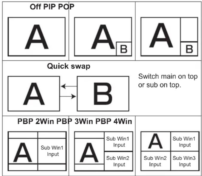
flowchart
graph TD
    A["Off PIP POP"] --> B["A"]
    B --> C["A_B"]
    C --> D["A"]
    D --> E["B"]
    F["Quick swap"] --> G["A ↔ B"]
    G --> H["B"]
    H --> I["Switch main on top or sub on top."]
    J["PBP 2Win PBP"] --> K["A Sub Win1 Input"]
    K --> L["A Sub Win1 Input"]
    L --> M["Sub Win2 Input"]
    N["3Win PBP 4Win"] --> O["A Sub Win1 Input"]
    O --> P["Sub Win2 Input"]
    P --> Q["A Sub Win1 Input"]
    R["Sub Win3 Input"] --> S["Sub Win2 Input"]
    S --> T["Sub Win3 Input"]
PIP size
Select the size of the sub picture in the PIP (Picture-in-Picture) mode.
Choose from: {Small} / {Medium} / {Large}.
PIP position
Select the position of the sub picture in the PIP (Picture-in-Picture) mode.
Choose from: {Bottom-Right} / {Bottom -Left} / {Top-Right} / {Top-Left}.
PIP change
Exchange input signal of Main and Sub for PIP / POP / Quick swap mode.
PIP reset
Reset all settings in the PIP menu to factory preset values.
NOTES:
- The PIP function is available only for the following condition: {Advanced option} - {Tiling} - {Enable} setting to [No].
- The PIP function is available only for certain signal source combinations as shown in the table below.
- The availability of the PIP function will also depend on the resolution of the input signal being used.
5.2.5 Configuration1 menu
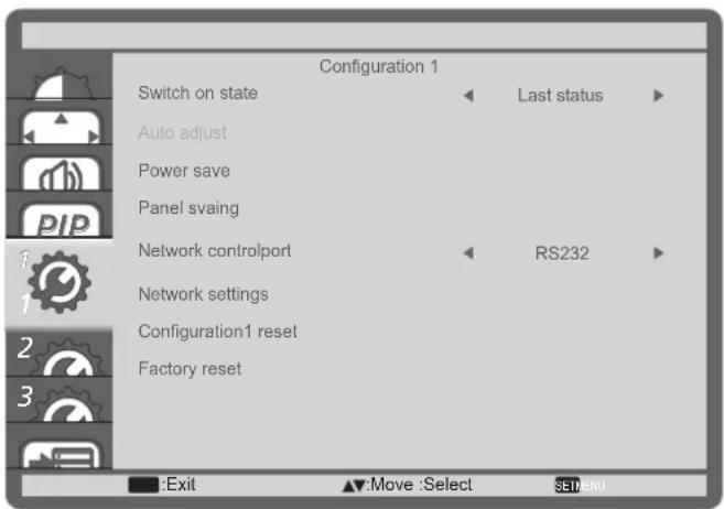
text_image
Configuration 1 Switch on state Auto adjust Power save Panel svaing Network controlport RS232 Network settings Configuration1 reset Factory reset Exit Move :Select SET/MENUSwitch on state
Select the display status used for the next time you connect the power cord.
- {Power off} - The display will remain off when the power cord is connected to a wall outlet.
- {Forced on} - The display will turn on when the power cord is connected to a wall outlet.
- {Last status} - The display will return to the previous power status (on/off/standby) when removing and replacing the power cord.
Auto adjust
Use this function to automatically optimize the display of VGA input image.
▲ NOTES: This item is functional for VGA input only.
Power save
Use this setting to reduce the power automatically.
- {RGB} - Select {On} to let the display enter power saving mode when no signal is detected from the PC mode (RGB color space) inputs after 10 seconds.
- {Video} - Select {On} to enter power saving mode when no signal is detected from the VIDEO mode (YUV color space) inputs after 10 seconds.
Panel saving
Choose to enable the panel saving functions and thus reduce the risk of "image persistence" or "ghost-imaging".
- {Cooling Fan} - Choose to adjust the cooling fan's speed of rotation. Select {Auto} to turn on/off the cooling fan according to the display's temperature.
Choose from: {Auto} / {Off} / {Low} / {Medium} / {High}.
NOTES:
- The default {Auto} option will start running the cooling fan if the temperature of 45^ (113°F) is reached, and stop running the cooling fan if the temperature of 43^ (109°F).
- A temperature-warning message will be shown on the screen if the temperature reaches 58^ (136°F). All key functions except [+] key will then be disabled.
- Once the temperature reaches 60°C (140°F), the display power will be shut down automatically.
- {Brightness} - Select {On} and the image brightness will be reduced to an appropriate level. The Brightness setting in the Picture menu will be unavailable when selected.
- {Anti-Burn-in ^TM } - Select the time interval ({Auto} / {10 \~ 900} Seconds / {Off}) for the display to slightly expand the image size and shift the position of pixels in four directions (up, down, left, or right). Activating Anti-Burn-in ^TM will disable H Position, V Position and Zoom Mode in the Screen Menu.
Network control port
Select the network control port.
Choose from: {RS232} / {Card OPS RS232} / {LAN ->RS232}.
▲ NOTES: After connected to your OPS device, the option {Card OPS RS232} is functional.
Network settings
Assign {IP address}, {Subnet Mask}, and {Default gateway} for the display.
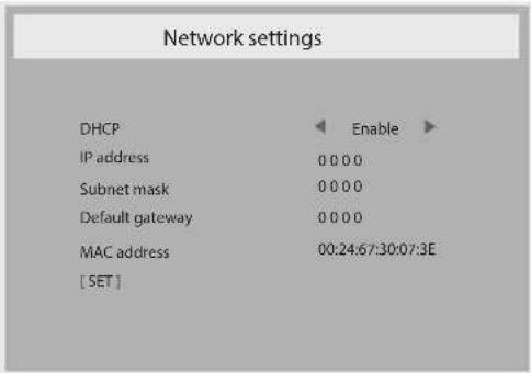
text_image
Network settings DHCP Enable IP address 0 0 0 0 Subnet mask 0 0 0 0 Default gateway 0 0 0 0 MAC address 00:24:67:30:07:3E [ SET ]- DHCP - Choose to enable or disable the DHCP function. If enabled, the display will be assigned IP address, Subnet mask and Default gateway automatically. If disabled, you will be prompted to enter the following values manually. Press select to [set] and [OK] button to store and save the chosen values.
- IP address
- Subnet mask
- Default gateway
- MAC address
Configuration1 reset
Reset all settings in Configuration1 menu to the factory preset values.
Factory reset
Reset all settings in the OSD menus of {Picture}, {Screen}, {Audio}, {PIP}, {Configuration1}, {Configuration2}, and {Advanced option} to the factory preset values.
Press [◀] or [▶] button to select {Reset}, and press [OK] button to do the reset.
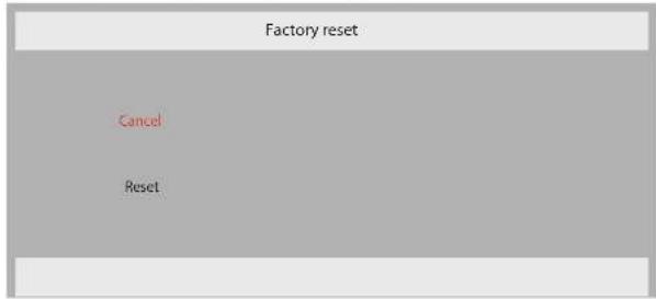
text_image
Factory reset Cancel Reset5.2.6 Configuration2 menu

text_image
Configuration 2 OSD turn off 45 OSD H-position 50 OSD V-position 50 Information OSD 10 Sec. Monitor ID 3 Heat status Monitor information DP version DP 1.1 :Exit ▲:Move :Select SET/ENDOSD turn off
Set the period of time the OSD (on-screen display) menu stays on the screen.
The options are: 0 120 seconds.
OSD H-position
Adjust the horizontal position of the OSD menu.
OSD V-position
Adjust the vertical position of the OSD menu.
Information OSD
Set the period of time the information OSD is displayed on the upper right corner of the screen. The information OSD will display when input signal is changed.
The information OSD will remain on the screen with {Off} selection.
The options are: {Off, 1 \~ 60} seconds.
Monitor ID
Set the ID number for controlling the display via the RS232C connection. Each display must have a unique ID number when multiple sets of this display are connected. Monitor ID number range is between 1 to 255.
Heat status
This function allows you to check the thermal status of the display at any time.
Monitor information
Shows information about your display, including model number and serial number.
| Monitor information | |
| Model Name: | QD-84 / QD-98 |
| Serial NO: | |
DP Version
The option are: {DP 1.1} / {DP 1.2}. The default is {DP 1.1}.
Human sensor
Set the display to turn on backlight if it does sensor human and turn off backlight after an amount of time specified
The options are: {Off, 10 \~ 60} minutes.
HDMI edid
The option are: {HDMI 1.4} / {HDMI 2.0}. The default is {HDMI 1.4}.
▲ NOTES: HDMI 2.0 option is to support HDMI 2.0 equipment use.
Configuration2 reset
Reset all settings in Configuration2 menu to the factory preset values.
5.2.7 Advanced option menu
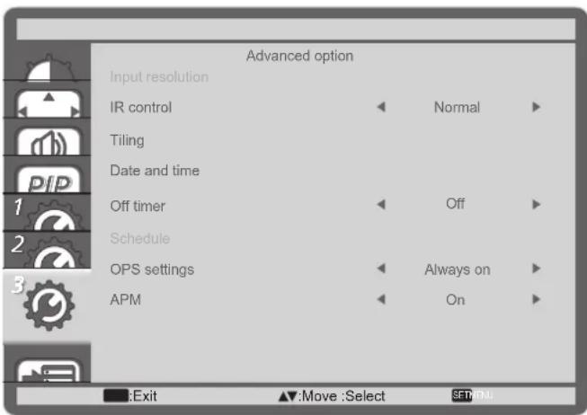
text_image
Advanced option Input resolution IR control Normal Tiling Date and time Off timer Off Schedule OPS settings Always on APM On Exit Move :Select SET/MenuInput resolution
Set the resolution of the VGA input. This is only required when the display is unable to detect the VGA input resolution correctly.
▲ NOTES: This item is functional for VGA input only.
The options are:
• {1024x768 / 1280x768 / 1360x768 / 1366x768}
• {1400x1050 / 1680x1050}
• {1600x1200 / 1920x1200}
• {Auto}: Determines the resolution automatically.
The selected settings will become effective after turning off the power and turning it on again.
IR control
Select the operation mode of the remote control when multiple displays are connected via an RS232C connection.
- {Normal} - All displays can be operated normally by the remote control unit.
- {Lock All} / - Lock the remote control function of this display. To unlock, press and hold the [i] INFO button on the remote control for 5 (five) seconds.
Tiling
With this function you can create a single large-screen matrix (video wall) that consists of up to 150 sets of this display (up to 10-sets on the vertical and 15-sets on the horizontal sides). This function requires a daisy-chain connection.
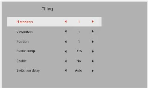
text_image
Tiling H monitors ← 1 ► V monitors ← 1 ► Position ← 1 ► Frame comp. ← Yes ► Enable ← No ► Switch on delay ← Auto ►Example: 2 x 2 screen matrix (4 displays)
H monitors = 2 displays
V monitors = 2 displays
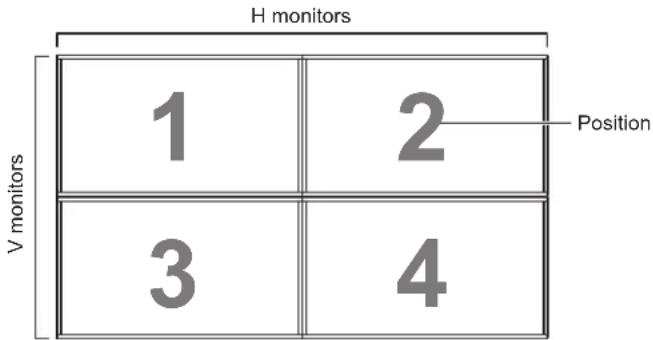
text_image
H monitors 1 2 Position V monitors 3 4Example: 5 x 5 screen matrix (25 displays)
H monitors = 5 displays
V monitors = 5 displays
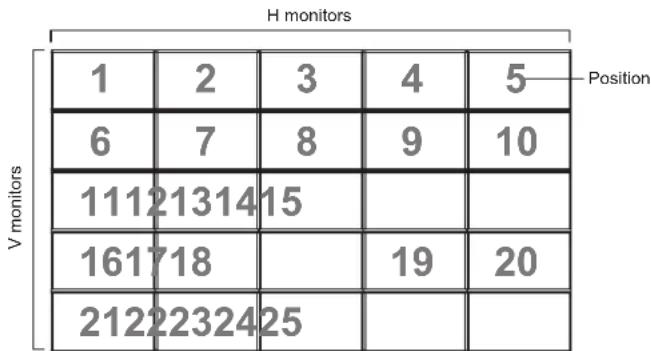
- {H monitors} - Select the number of displays on the horizontal side.
- {V monitors} - Select the number of displays on the vertical side.
- {Position} - Select the position of this display in the screen matrix.
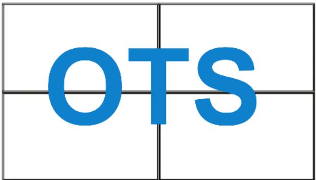
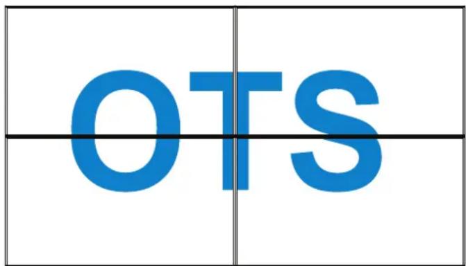
- {Frame comp.} - Choose to turn the frame compensation function on or off. If selected {Yes}, the display will adjust the image to compensate for the width of the display bezels in order to accurately display the image.
Frame comp. - Yes
text_image
OTSFrame comp. - No
text_image
OTS- {Enable} - Choose to enable or disable the Tiling function. If enabled, the display will apply the settings in {H monitors}, {V monitors}, {Position}, and {Frame comp.}.
- {Switch on delay} - Set the power-on delaying time (in seconds). The default option {Auto} allows a sequential powering-on for each display by their ID number when multiple displays are connected. The options are: {Off / Auto / 2 \~ 255}
▲ NOTES: The Tiling function will be disabled during using PIP function.
Date and time
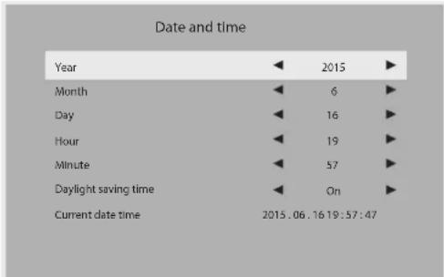
Adjust the current date and time for the display's internal clock.
text_image
Date and time Year 2015 Month 6 Day 16 Hour 19 Minute 57 Daylight saving time On Current date time 2015.06.16 19:57:47- Press [OK] button to enter the submenu.
- Press [1] or [7] button to toggle between {Year}, {Month}, {Day}, {Hour}, {Minute}, and {Daylight saving time}.
- Press [→] or [→] button to adjust all settings
Off Timer
Set the display to turn itself off to standby mode within an amount of time specified.
The options are: {Off, 1 \~ 24} hours from current time.
▲ NOTES: When the "Off timer" is activated, the "Schedule" settings will be disabled.
Schedule
This function allows you to program up to 7 (seven) different scheduled time intervals for the display to activate.
You can select:
- The time for the display to turn on and turn off.
- The days in a week for the display to activate.
- Which input source the display will use for each scheduled activation period.
▲ NOTES: We recommend you to set up current date and time in the {Date and time} menu before using this function.
- Press [OK] or [▶] button to enter the submenu.

text_image
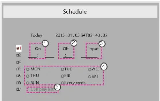
Schedule Today 2015.01.03 SAT02:43:32 On Off Input : : _ ☐2 ☐3 ☐4 ○ MON ○ TUE ○WED ☐5 ○ THU ○FRI ○SAT ☐6 ○ SUN ○Every week ☐7 USB play list- Press [] or [] button to select a schedule item (item number 1 \~ 7), and then press [OK] button to mark it the item number.
flowchart
graph TD
    A["1: On"] --> B["2: Off"]
    B --> C["3: Input"]
    D["4: MON"] --> E["5: USB play list"]
    F["5: THU"] --> E
    G["6: SUN"] --> E
    H["7: USB play list"] --> E
    I["Mon"] --> J["TUE"]
    K["FRI"] --> L["WED"]
    M["Every week"] --> N["SAT"]
- Press [→] or [→] button to select the schedule:
① Power-on schedule: Press [] or [] button to set the hour and minute for the display to turn on.
②Power-offschedule:Press [1] or [1] button to set the hour and minute for the display to turn off.
Select or leave an empty “____” for both the hour and minute slot if you do not want to use this power-on or power-off schedule.
③ Input-source selection: Press [1] or [7] button to select an input source. If no input source is selected, the input source will remain the same as last selected.
OSD MENU
④ Date schedule: Press [→] button to select which day in a week this schedule item will be take effect, and then press the [OK] button.
⑤ When Input-source select to USB, enable to access USB play list setting:
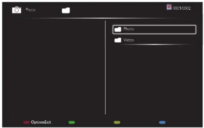
text_image
Photo 0001:0002 Photo Video OptionsExit- Press [1] [2] buttons to choose files.
- Press [+]▶ buttons to switch Playlist and File Manager.
- Press [OK] button to set or clear the playlist.
- To save the playlist, press [—] and choose Save list.
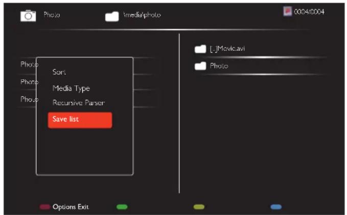
text_image
Photo xmedia\photo 0004/004 Phone Sort Media Type Recursive Parser Save list [L]Movie.avi Photo Options Exit- For additional schedule settings, press [←], then repeat the steps above. A check mark in the box next to the number of the schedule item indicates that the selected schedule is in effect.
NOTES:
- If the schedules overlap, the scheduled power-on time takes priority over scheduled power-off time.
- If there are two schedule items programmed for the same time, the highest numbered schedule takes priority. For example, if schedule items #1 and #2 both set the display to power on at 7:00 AM and off at 5:00 PM, then only schedule item #1 will take effect.
• Each Playlist supports up to 30 files. - Playlist will not be cleared after {Factory reset}. You have to manually remove the files or delete usb_schedulinglist.txt in the USB.
OPS settings
Set the OPS configuration under each power condition.
- {Auto} - After selecting {Card OPS} for video source input, the OPS will be set to off when the display power is set to off, or set to on when the display power is set to on. When set to other video source inputs, the OPS will always be set to on.
- {Always off} - The OPS will always be set to off.
- {Always on} - The OPS will always be set to on.
APM
Power save setting.
- {Off} - No signal, direct shutdown. (Default).
- {On} - No signal, enter into Power Save mode..
Language
Select the language used in the OSD menu.
The options are: {English} / {Deutsch} / {简体中文} / {Français} / {Italiano} / {Español} / {繁體中文} / {日本語}.
Advanced option reset
Reset all settings except {Date and Time} in the Advanced option menu to factory preset values.
- Press [OK] or [▶] button to enter the submenu.
- Press [→] or [→] button to select {Reset} and press the [OK] button to restore settings to factory preset values.
- Press the [←] button or select {Cancel} and press the [OK] button to cancel and then return to the previous menu.
5.2.8 Input menu
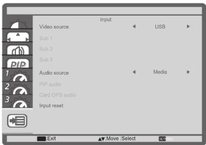
text_image
Input Video source Sub 1 Sub 2 Sub 3 Audio source PIP audio Card OPS audio Input reset USB Media Exit Move :Select SETMENUVideo source
Select a video input source.
Choose from: {Displayport} / {DVI-D} / {VGA} / {HDMI1} / {HDMI2} / {HDMI3} / {Component} / {Video} / {USB} / {Card OPS}.
OSD MENU
Sub 1
Select the input signal for the sub Win1 picture.
Choose from: {Displayport} / {DVI-D} / {VGA} / {HDMI1} / {HDMI2} / {HDMI3} / {Component} / {Video} / {USB} / {Card OPS}.
Sub 2
Select the input signal for the sub Win2 picture.
Choose from: {Displayport} / {DVI-D} / {VGA} / {HDMI1} / {HDMI2} / {HDMI3} / {Component} / {Video} / {USB} / {Card OPS}.
Sub 3
Select the input signal for the sub Win3 picture.
Choose from: {Displayport} / {DVI-D} / {VGA} / {HDMI1} / {HDMI2} / {HDMI3} / {Component} / {Video} / {USB} / {Card OPS}.
Audio source
Select the audio input source according to the audio signal source connected to the audio input and HDMI sockets on the display.
Choose from: {Analog} / {Displayport} / {Audio1} / {Audio2} / {Media}.
PIP audio
Select the audio source the PIP (Picture-in-Picture) mode.
- {Main} - Select audio from the main picture
- {Sub 1} - Select audio from the sub1 picture.
- {Sub 2} - Select audio from the sub2 picture.
- {Sub 3} - Select audio from the sub3 picture.
Card OPS audio
Select the analog or digital audio mode for card OPS.
Input reset
Reset all settings in the Input menu to factory preset values.
6.1 USB device compatibility
USB Video Subtitle Formats (for language subtitles, etc.)
| File Extensions | Container | Video codec | Maximum resolution | Max.Frame Rate (fps) | Max.Bit Rate (Mbps) | Audio codec |
| .mpgmpeg.vob | PS | MPEG-1 | 1920x1080 25p,30p,50i | 60i 30 | MPEG-1(L1&L2),MPEG-1,2,2.5L3, AAC/HE-AAC(v1&v2),DVD-PCM,AC3 | |
| MPEG-2 | 1920x1080 25p,30p,50i | 60i 30 | ||||
| MPEG-4ASP | 1920x1080 25p,30p,50i,60i 30 | |||||
| H.264 1920x1080 p,30p,50p,60p,60i 30 | ||||||
| .ts TS | MPEG-2 | 1920x1080 25p,30p,50i | 60i 30 | MPEG-1(L1&L2),MPEG-1,2,2.5L3,AAC/HE-AAC(v1&v2),AC3,E-AC3,Dolby Pulse | ||
| MPEG-4ASP | 1920x1080 25p,30p,50i,60i 30 | |||||
| H.264 1920x1080 | 25p,30p,50p,60p,60i | 30 | ||||
| MVC | 1920x1080i@field rate=50, 60Hz1920x1080p@frame rate=24, 25,30Hz1280x720p@frame rate=50, 60Hz | -30 | ||||
| .ts.m2ts.mts.mt2 | MaTSTTS | MPEG-2 | 1920x1080 25p,30p,50i | 60i 30 | MPEG-1(L1&L2),MPEG-1,2,2.5L3,AAC/HE-AAC(v1&v2),AC3,E-AC3,Dolby Pulse | |
| MPEG-4ASP | 1920x108O 25p,30p,50i,60i 30 | |||||
| H.264 1920x1080 | 25p,30p,50p,60p,60i | 30 | ||||
| MVC | 1920x1080i @ field rate=50, 60Hz1920x1080p @ frame rate=24, 25,30Hz1280x720p @ frame rate=50, 60Hz | -30 | ||||
| .ts.m2ts.mts | AVCHD | MPEG-2 | 1920x1080 25p,30p,50i | 60i 30 MPEG- | 1(L1&L2),MPEG-1,2,2.5L3, AAC/HE-AAC(v1&v2),AC3,E-AC3,Dolby Pulse | |
| MPEG-4ASP | 1920x1080 25p,30p,50i,60i 30 | |||||
| H.264 1920x1080 | 25p,30p,50p,60p.60i | 30 | ||||
| .ts.m2ts.mts | AVCHD MVC | 1920x1080i@field rate=50, 60Hz1920x1080p@frame rate=24, 25,30Hz1280x720p @ frame rate=50, 60Hz | -30 | MPEG-1(L1&L2),MPEG-1,2,2.5L3, AAC/HE-AAC(v1&v2),AC3,E-AC3,Dolby Pulse | ||
| .m4v M4V | H.264 1920x1080 | 25p,30p,50p,60p,60i | 30 AAC | |||
USB DEVICE COMPATIBILITY
| File Extensions | Container | Video codec | Maximum resolution | Max.Frame Rate (fps) | Max. Bit Rate (Mbps) | Audio codec |
| .ism/ Manifest .mpd | frag MP4 | H.264 1920x1080 25p,30p,50p,60p,60i 30 | AAC/HE-AAC(v1&v2), AC3,E-AC3,WMA, WMA-PRO | |||
| MVC | 1920x1080i@field rate=50, 60Hz1920x1080p@frame rate=24, 25,30Hz1280x720p @ frame rate=50, 60Hz | -30 | ||||
| .mp4 MP4 | MPEG-4 ASP | 1920x1080 25p,30p,50i,60i 30 | AAC/HE-AAC(v1&v2), AC3,E-AC3,WMA, WMA-PRO | |||
| H.264 1920x1080 30 | ||||||
| MVC | 1920x1080i@field rate=50, 60Hz1920x1080p@frame rate=24, 25,30Hz1280x720p @ frame rate=50, 60Hz | -30 | ||||
| WMV9/ VC1 | 1920x1080 30p,60i 30 | |||||
| .mkv .mk3d | MKV | MPEG-4 ASP | 1920x1080 25p,30p,50i,60i 30 | MPEG-1(L1&L2), MPEG-1,2,2.5 L3, AAC/HE-AAC (v1&v2), AC3,E-AC3, WMA, WMA-PRO | ||
| H.264 1920x1080 30 | ||||||
USB Multimedia Formats
| File Extensions | Container | Video codec | Maximum resolution | Frequency (kHz) | Max.Bit Rate (Mbps) | Audio codec |
| .mp3 MP3 | - - 48 384 MP | EG-1,2,2.5 | L3 | |||
| .wma.asf | WMA(V2 up to V9.2) | - - 48 | 192 WMA | |||
| .wma WMA | Pro - - 96 7 | 68 WMA,W | MA Pro | |||
| .wav(PC) LPCM | - - 192 768 LPCM | |||||
| .aif(mac).aiff(mac) | LPCM - - | 192 768 LPCM | ||||
| .aac.mp4.m4a | AAC - - 48 1024 | AAC,HE-AAC(v1&v2) | ||||
| .pls.m3u | Playlists - - - | - | ||||
| .m4a M4A | - - 48 1024 | AAC,HE-AAC(v1&v2) |
USB Photo file format type: JPEG, BMP, PNG, GIF
NOTE:
- Sound or video may not work if the contents have a standard bit rate/frame rate above the compatible Frame/sec listed in the table above.
- Video content with a Bit rate or Frame rate larger than the rate specified in the table above can cause choppy video during playback.
CHAPTER 7: INPUT MODE
FHD Preset Mode (VGA/DVI timing support):
| Item | Resolution H.Freq. (KHz) V.Freq. (Hz) BW(MHz) | |||
| 1 64 | 0x350 31.469 | 70.086 25.175 | ||
| 2 64 | 0x480 31.469 | 59.94 25.175 | ||
| 3 64 | 0x480 35 66.6 | 7 30.240 | ||
| 4 64 | 0x480 37.861 | 72.809 31.500 | ||
| 5 64 | 0x480 | 37.5 | 75 31.500 | |
| 6 72 | 0x400 31.469 | 70.087 28.322 | ||
| 7 80 | 0x600 | 35.156 56.25 36.000 | ||
| 8 80 | 0x600 37.879 | 60.317 | 40.000 | |
| 9 80 | 0x600 48.077 | 72.188 50.000 | ||
| 10 | 800x600 46 | 8.875 75.000 49.500 | ||
| 11 | 832x624 | 49.726 | 74.551 | 57.284 |
| 12 | 848x480 | 31 | 60.000 | 33.750 |
| 13 | 960x720 | 56.4 | 75.000 | 72.420 |
| 14 | 960x720 | 44.74 | 59.973 | 57.580 |
| 15 | 1024x768 | 48.363 | 60.004 | 65.000 |
| 16 | 1024x768 | 56.476 | 70.069 | 75.000 |
| 17 | 1024x768 | 60.023 | 75.029 | 78.750 |
| 18 | 1024x768 6 | 1.08 75.781 | 86.000 | |
| 19 | 1024x768 | 35.5 | 43.000 | 44.900 |
| 20 | 1152x864 | 53.986 | 59.985 | 79.900 |
| 21 | 1152x864 | 53.783 | 59.959 | 81.750 |
| 22 | 1152x864 | 63.851 | 70.012 | 94.499 |
| 23 | 1152x864 | 67.5 | 75.000 | 108.000 |
| 24 | 1152x870 6 | 8.681 75.062 | 100.000 | |
| 25 | 1152x900 6 | 1.846 66.004 | 94.500 | |
| 26 | 1152x900 | 71.809 | 76.149 | 108.000 |
| 27 | 1280x720 | 44.772 | 60.000 | 74.500 |
| 28 | 1280x720 | 52.5 | 70.000 | 89.040 |
| 29 | 1280 x768 | 47.776 | 59.870 | 79.500 |
| 30 | 1280 x768 | 60.289 | 74.893 | 102.250 |
| 31 | 1280x800 | 49.7 | 59.810 | 83.500 |
| 32 | 1280x800 | 62.8 | 74.930 | 106.500 |
| 33 | 1280x960 | 60 | 60.000 | 108.000 |
| 34 | 1280x960 | 75.171 | 75.021 | 129.895 |
| 35 | 1280x1024 | 63.981 | 60.020 | 108.000 |
| 36 | 1280x1024 | 71.691 | 67.189 | 117.000 |
| 37 | 1280x1024 7 | 76.02 71.448 130.223 | ||
| 38 | 1280x1024 | 79.976 | 75.025 | 135.000 |
| 39 | 1280x1024 | 81.13 | 76.110 | 135.000 |
| 40 | 1360x768 | 47.712 | 60.015 | 85.500 |
| 41 | 1366x768 | 47.712 | 59.790 | 85.500 |
| 42 | 1440x900 5 | 56.469 59.901 | 88.750 | |
| 43 | 1440x900 5 | 56.935 59.887 | 106.500 | |
| 44 | 1440x900 7 | 70.635 74.984 | 136.750 | |
| Item R | Resolution H.Freq. (KHz) V.Freq. (Hz) BW(MHz) | |||
| 45 | 1400x1050 | 64.744 | 59.948 | 101 |
| 46 | 1440x1050 65.3 | 60.000 | 121.750 | |
| 47 | 1400x1050 | 82.278 | 74.867 | 156 |
| 48 | 1600x900 55 | 54 60.000 | 97.750 | |
| 49 | 1600x1200 | 75 | 60 | 162 |
| 50 | 1680x1050 65.29 | 59.954 | 146.250 | |
| 51 | 1680x1050 | 64.674 | 59.883 | 119.000 |
| 52 | 1920x1080 | 66.587 | 59.934 | 138.500 |
| 53 | 1920x1080 67.5 | 60.000 | 148.500 | |
| 54 | 1920x1080 | 67.1584 59.963 | 173.000 | |
| 55 | 1920x1080 67.08 | 60 | 172.798 | |
| 56 | 1920x1200 | 74.038 | 59.950 | 154.000 |
UHD Preset Mode (DP/HDMI timing support):
| Item | Resolution H.Freq. (KHz) V.Freq. (Hz) BW(MHz) | ||||
| 1 38 | 40x2160 53.946 | 23.900 296.703 | for HDMI | ||
| 2 38 | 40x2160 54 24.000 | 297.000 for HDMI | |||
| 3 38 | 40x2160 56.25 25.000 | 297.000 for HDMI | |||
| 4 38 | 40x2160 67.432 | 29.900 296.703 | for HDMI | ||
| 5 38 | 40x2160 67.5 30.000 | 297.000 for HDMI | |||
| 6 40 | 96x2160 54 24.000 | 297.000 for HDMI | |||
| 7 38 | 40x2160 | 135 | 60.000 594.000 | for HDMI | |
| 8 | 3840x2160 | 133.312 | 59.997 | 533.25 | for DP |
| 9 38 | 40x2160 65.688 | 29.981 | 262.75 For | DP/HDMI | |
Video timing support (HDMI/DVD HD/DVI):
480i, 480p, 576i, 576p, 720p, 1080i, 1080p, 4Kx2K (except DVI).
NOTE:
- The PC text quality is optimum in HD 1080 mode (1920 x 1080, 60Hz).
- Your PC display screen might appear different depending on the manufacturer (and your particular version of Windows).
- Check your PC instruction book for information about connecting your PC to a display.
- If a vertical and horizontal frequency-select mode exists, select 60Hz (vertical) and 31.5KHz (horizontal). In some cases, abnormal signals (such as stripes) might appear on the screen when the PC power is turned off (or if the PC is disconnected). If so, press the [INPUT] button to enter the video mode. Also, make sure that the PC is connected.
- When horizontal synchronous signals seem irregular in RGB mode, check PC power saving mode or cable connections.
- The display settings table complies to the IBM/VESA standards, and based on the analog input.
- The DVI support mode is regarded as same to the PC support mode.
- The best timing for the vertical frequency to each mode is 60Hz.
- When the input source is Component or Video, the Information OSD will be displayed slowly than other input sources.
- No matter the resolution of Component source or Video source input, the result of Zoom mode setting is the same as 1080P resolution.
CHAPTER 8: PIXEL DEFECT POLOCY
We strive to deliver the highest quality products and use some of the industry's most advanced manufacturing processes whilst practicing stringent quality control. However, pixel or sub-pixel defects on the PDP / TFT panels used in Plasma- & LCD- displays are sometimes unavoidable. No manufacturer can guarantee that all panels will be free from pixel defects, but we guarantee that any Plasma- & LCD- displays with an unacceptable number of defects will be repaired during the warranty period in line with your local guarantee conditions.
This notice explains the different types of pixel defects and defines the acceptable defect level for the LCD screen. In order to qualify for repair under warranty, the number of pixel defects must exceed a certain level as shown in the reference table. If the LCD screen is within specification a warranty exchange / claim back will be refused. Additionally, because some types or combinations of pixel defects are more noticeable than others, We set even higher quality standards for those.
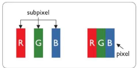
8.1 Pixels and Sub-Pixels
flowchart
graph TD
    A["subpixel"] --> B["R"]
    A --> C["G"]
    A --> D["B"]
    E["pixel"] --> F["R"]
    E --> G["G"]
    E --> H["B"]
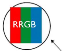
A pixel, or picture element, is composed of three sub-pixels in the primary colors of red, green and blue. Many pixels together form an image. When all sub-pixels of a pixel are lit, the three colored sub-pixels together appear as a single white pixel. When all are dark, the three colored sub-pixels together appear as a single black pixel. Other combinations of lit and dark sub-pixels appear as single pixels of other colors.
8.2 Types of Pixel Defects + Dot Definition
Pixel and sub-pixel defects appear on the screen in different ways. There are three categories of pixel defects and several types of sub-pixel defects within each category.
Dot definition = What is a defective "Dot"? :
One or more defective, adjacent sub-pixel are defined as one "dot". The no. of defective sub-pixels are not relevant to define a defective dot. This means that a defective dot can consist of one, two or three defective sub-pixels which can be dark or lit.
text_image
RRGBOne dot = One Pixel; consists of three sub-pixels of Red, Green, and Blue.
8.3 Bright Dot Defects
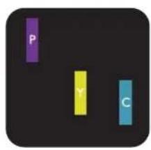
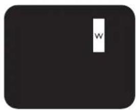
Bright dot defects appear as pixels or sub-pixels that are always lit or "on". These are the examples of bright dot defects:

text_image
G R BOne lit red, green or blue sub pixel
text_image
P Y CTwo adjacent lit sub pixels:
Red + Blue = Purple
Red + Green = Yellow
Green + Blue = Cyan (Light Blue)
text_image
WThree adjacent lit sub pixels (one white pixel)
8.4 Dark Dot Defects
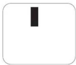
Black dot defects appear as pixels or sub-pixels that are always dark or "off". These are the examples of black dot defects:
natural_image
Simple black vertical rectangle inside a rounded rectangle (no text or symbols)One dark dot Two adja
natural_image
Simple black rectangle centered within a rounded square border (no text or symbols)cent dark dots = 1 pair of dark dots

flowchart
graph TD
    A[" "] --> B[" "]
Two dark dots, specifications defines the minimum distance between dark dots
8.5 Proximity of Pixel Defects
Because pixel and sub-pixels defects of the same type that are nearby one another may be more noticeable, We also specify tolerances for the proximity of pixel defects. In the table below you can find specifications about:
- Allowed amount of adjacent dark dots = (adjacent dark dots = 1 pair of dark dots)
• Minimum distance between dark dots
• Total no. of all defective dots
8.6 Pixel Defect Tolerances
In order to qualify for repair due to pixel defects during the warranty period, a PDP / TFT panel in a Plasma / LCD- display must have pixel or sub-pixel defects exceeding the tolerances listed in the following table.
| BRIGHT DOT EFFECT ACCEPTABLE LEVEL | |
| 1 lit sub pixel 2 | |
| BLACK DOT EFFECT ACCEPTABLE LEVEL | |
| 1 dark sub pixel 10 | |
| TOTAL DOT DEFECTS OF ALL TYPES 12 |
NOTE: * 1 or 2 adjacent sub pixel defects = 1 dot defect
8.7 MURA
Dark spots or patches may occasionally appear on some liquid crystal display (LCD) panels. This is known within the industry as Mura, which is a Japanese term for “unevenness.” It is used to describe an irregular pattern or area in which uneven screen uniformity appears under certain conditions. Mura is a result of the deterioration of the liquid crystal alignment layer and is most commonly caused by long-term operation under high ambient temperatures. It is an industry-wide phenomenon and Mura is not repairable. It is also not covered by our warranty terms.
Mura has been around since the introduction of LCD technology and with screens getting bigger and in operation 24/7, many displays are running in low light conditions. This all adds to the possibility of Mura affecting displays.
HOW TO SPOT MURA
There are many symptoms of Mura and also multiple causes. Several of these are listed below:
- Impurities or foreign particles in the crystal matrix
- Uneven distribution of LCD matrix during manufacturing
• Non-uniform luminance distribution of the backlight - Panel assembly induced stress
- Flaws within the LCD cells
• Thermal induced stress - high temperature operation over long periods of time
HOW TO AVOID MURA
Although we can not guarantee the complete eradication of Mura every time, in general the appearance of Mura can be minimized by these methods:
- Lower the backlight brightness
- Use a screen saver
- Reduce the ambient temperature around the unit
CHAPTER 9: CLEANING AND TROUBLESHOOTING
9.1 Cleaning
Caution When Using the Display
- Do not bring your hands, face or objects close to the ventilation holes of the display. The top of the display is usually very hot due to the high temperature of exhaust air being released through the ventilation holes. Burns or personal injuries may occur if any body parts are brought too close. Placing any object near the top of the display could also result in heat related damage to the object as well as the display itself.
- Be sure to disconnect all cables before moving the display. Moving the display with its cables attached may damage the cables and thus cause fire or electric shock.
- Disconnect the power plug from the wall outlet as a safety precaution before carrying out any type of cleaning or maintenance procedure.
Front Panel Cleaning Instructions
- The front of the display has been specially treated. Wipe the surface gently using only a cleaning cloth or a soft, lint-free cloth.
- If the surface becomes dirty, soak a soft, lint-free cloth in a mild detergent solution. Wring the cloth to remove excess liquid. Wipe the surface of the display to remove dirt. Then use a dry cloth of the same type to dry.
- Do not scratch or hit the surface of the panel with fingers or hard objects of any kind.
- Do not use volatile substances such as insert sprays, solvents and thinners.
Cabinet Cleaning Instructions
- If the cabinet becomes dirty, wipe the cabinet with a soft, dry cloth.
- If the cabinet is extremely dirty, soak a lint-free cloth in a mild detergent solution. Wring the cloth to remove as much moisture as possible. Wipe the cabinet. Use another dry cloth to wipe over until the surface is dry.
- Do not allow any water or detergent to come into contact with the surface of the display. If water or moisture gets inside the unit, operating problems, electrical and shock hazards may result.
- Do not scratch or hit the cabinet with fingers or hard objects of any kind.
- Do not use volatile substances such as insert sprays, solvents and thinners on the cabinet.
- Do not place anything made from rubber or PVC near the cabinet for any extended periods of time.
9.2 Troubleshooting
| Symptom Possible Cause Remedy | ||
| No picture is displayed 1. The power cord is disconnected.2. The main power switch on the back of the display is not switched on.3. The selected input has no connection.4. The display is in standby mode. | Plug in the power cord.Make sure the power switch is switched on.Connect a signal connection to the display. | |
| Interference displayed on the display or audible noise is heard | Caused by surrounding electrical appliances or fluorescent lights. | Move the display to another location to see is the interference is reduced. |
| Color is abnormal The signal cable is not connected properly. | Make sure that the signal cable is attached firmly to the back of the display. | |
| Picture is distorted with abnormal patterns | The signal cable is not connected properly.The input signal is beyond the capabilities of the display. | Make sure that the signal cable is attached firmly.Check the video signal source to see if it is beyond the range of the display. Please verify its specifications with this display's specification section. |
| Display image doesn't fill up the full size of the screen | The zoom mode is not set correctly.Scan Mode may be set incorrectly to underscan.If the image exceeds the screen size, Scan Mode may need to be set to Underscan. | Use the Zoom mode or Custom zoom function in the Screen menu to fine tune display geometry and time frequency parameter. |
| Can hear sound, but no picture Improperly connected source signal cable. | Make sure that both video inputs and sound inputs are correctly connected. | |
| Can see picture but no sound is heard | Improperly connected source signal cable.Volume is turned all the way down.{Mute} is turned on.No external speaker connected. | Make sure that both video inputs and sound inputs are correctly connected.Press [+] or [+button to hear sound.Switch MUTE off by using the [×] button.Connect external speakers and adjust the volume to a suitable level. |
| Some picture elements do not light up | Some pixels of the display may not turn on. | This display is manufactured using an extremely high level of precision technology: however, sometimes some pixels of the display may not display. This is not a malfunction. |
| After-Images can still be seen on the display after the display is powered off. (Examples of still pictures include logos, video games, computer images, and images displayed in 4:3 normal mode) | A still picture is displayed for an over extended period of time | Do not allow a still image to be displayed for an extended period of time as this can cause a permanent after-image to remain on the display. |
CHAPTER 10: TECHNICAL SPECIFICATIONS
10.1 QD-84 & QD-98
| Display QD-84 QD-98 | ||
| Screen Size (Active Area) 84" (213.5 cm) LCD 97.5" (247.7 cm) LCD | ||
| Aspect Ratio 16:9 16:9 | ||
| Number of pixels 3840 (H) x 2160 (V) | 3840 (H) x 2160 (V) | |
| Pixel pitch 0.4845 x 0.4845 mm 0.5622 x 0.5622 mm | ||
| Color depth | 10 bit(D), 1.06 Billion colors | 10 bit(D), 1.06 Billion colors |
| Brightness 500 nits (typ) 500 nits (typ) | ||
| Contrast ratio 1400:1 (typ) | 1300:1 (typ) | |
| Viewing angle | 178 degrees | 178 degrees |
| In/Out Terminals | QD-84 QD-98 | |
| Speaker Output | Internal SpeakersExternal Speakers | 10W (L) + 10W (R) [RMS]/8Ω1 Way 1 Speaker System82 dB/W/M/160 Hz ~ 13 KHz |
| SPDIF Output | SPDIF Port | Serial digital audio output when input is HDMI |
| Audio Output | 3.5 mm Stereo x 1 | 0.5V [rms] (Normal) / 2 Channel (L+R) |
| Audio Input | RCA Jack x 23.5 mm Stereo x 1 | 0.5V [rms] (Normal) / 2 Channel (L+R) |
| RS232C | 2.5mm Phonejack x 2 | RS232C in/RS232C out |
| RJ-45 | RJ-45 Jack x 1 (8 pin) | 10/100 LAN Port |
| HDMI Input | HDMI Jack x 3(Type A) (19 pin) | Digital RGB: TMDS (Video + Audio)MAX: Video - 720p, 1080p, 1920 x 1080/60 Hz (WUXGA),4K/2K 30/60HzAudio - 48 KHz/ 2 Channel (L+R)Supports LPCM only |
| DVI-D Input | DVI-D jack | Digital RGB: TMDS (Video) |
| VGA Input | D-Sub Jack x 1(15 pin) | Analog RGB: 0.7V [p-p] (75Ω), H/CS/V: TTL (2.2kΩ),SOG: 1V [p-p] (75Ω)MAX: 720p, 1080p, 1920 x 1080/60 Hz (WUXGA) |
| Component Input | RCA Jack x 3 | Y: 1V [p-p] (75Ω), Pb: 0.7V [p-p] (75Ω), Pr: 0.7V [p-p](75Ω)MAX: 480i, 576i, 480p, 576p, 720p, 1080i, 1080p |
| Video Input | RCA x 1(Share with Component_Y) | Composite 1V [p-p] (75Ω) |
TECHNICAL SPECIFICATIONS
General QD-84 QD-98
| Power Supply AC 100 - 240V, 50 - 60Hz AC 100 - 240V, 50 - 60Hz | ||
| Power Consumption | 600 W (max) 700 W (max) | |
| 400 W (typ) 500 W (typ) | ||
| NA (EPA 6.0) NA (EPA 6.0) | ||
| <0.5W (standby mode) <0.5W (standby mode) | ||
| Dimensions (Without Stand) 1910.0(W) x 1102.0(H) x 2193.2(W) x 1248.2(H) x 77.8(D) mm 89.8(D) mm | ||
| Weight (Without Stand) 70.0 Kg 91.4 Kg | ||
| Gross Weight (Without Stand) 102.5 Kg 134.5 Kg | ||
Environmental Condition QD-84 QD-98
| Temperature Operational | 0 ~ 40°C | 5 ~ 40°C | |
| Storage | -20 ~ 60°C | -20 ~ 60°C | |
| Humidity | Operational | 20 ~ 80% (without condensation) | 20 ~ 80% (without condensation) |
| Storage | 5 ~ 95% (without condensation) | 5 ~ 95% (without condensation) | |
| Altitude | Operational | 0 ~ 5,000 m | 0 ~ 5,000 m |
| Storage / Shipment | 0 ~ 9,000 m | 0 ~ 9,000 m |
| Internal Speaker | QD-84 QD-98 | |
| Type | 1 Way 1 Speaker | 1 Way 1 Speaker |
| Input | 10 W (RMS) | 10 W (RMS) |
| Impedance | 8Ω | 8Ω |
| Output Sound Pressure 82 dB/W/M | 82 dB/W/M | |
| Frequency Response | 160 Hz ~ 13 KHz | 160 Hz ~ 13 KHz |
| Product Fiche | QD-84 QD-98 | |
| Energy Efficiency Class | C | A |
| Visible Screen Size | 213.5cm/84 inches | 247.7cm/97.5 inches |
| On Mode Power Consumption (W) | 389W | 314W |
| Annual Energy Consumption (kWh) | 568 KWh | 458 KWh |
| Standby Power Consumption (W) | 0.5W | 0.5W |
| Off Mode Power Consumption (W) | 0.5W | 0.5W |
| Display Resolution (Pixels) 3840x2160 | 3840x2160 | |
| Network Standby (W) | 6W | 6W |
NOTE: All specifications are subject to change without prior notice.
Company Address: 5F-1, No. 3-1, Park Street, Nangang District, Taipei, 11503, Taiwan.