F430 - Exercise bike BodyCraft - Free user manual and instructions
Find the device manual for free F430 BodyCraft in PDF.


User questions about F430 BodyCraft
0 question about this device. Answer the ones you know or ask your own.
Ask a new question about this device
Download the instructions for your Exercise bike in PDF format for free! Find your manual F430 - BodyCraft and take your electronic device back in hand. On this page are published all the documents necessary for the use of your device. F430 by BodyCraft.
USER MANUAL F430 BodyCraft
Assembly Instructions
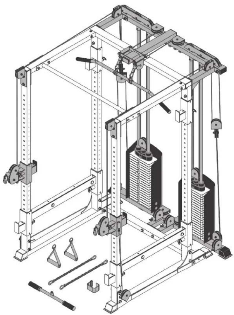
natural_image
Technical line drawing of a mechanical lifting frame assembly with multiple supports and levers (no text or symbols)
max. 360 kg

\~ 180 Min.


87.5 kg
L 164 | W 150 | H 211
BCF438.01.01
Art. No. BC-F438
Content
1 GENERAL INFORMATION 6
1.1 Technical Data 6
1.2 Personal Safety 7
1.3 Set-Up Place 8
2 ASSEMBLY 9
2.1 General Instructions 9
2.2 Scope of Delivery 10
2.3 Assembly 12
3.2 Cable Adjustment 23
3 STORAGE AND TRANSPORT 23
3.1 General Instructions 23
4 TROUBLESHOOTING, CARE AND MAINTENANCE 24
4.1 General Instructions 24
4.2 Faults and Fault Diagnosis 24
4.3 Maintenance and Inspection Calendar 25
5 DISPOSAL 25
6 RECOMMENDED ACCESSORIES 26
7 ORDERING SPARE PARTS 27
7.1 Serial Number and Model Name 27
7.2 Parts List 28
7.3 Exploded Drawing 30
8 WARRANTY 31
9 CONTACT 33
Dear customer,
thank you for choosing training equipment of the brand Bodycraft. Bodycraft equipment inspires with its multifunctionality and excellent quality. In terms of innovation and technology, it is one of the highest quality fitness equipment for home use. Bodycraft multi gyms, for example, offer a very wide range of exercise possibilities. This ranges from traditional strength training such as bench presses and rehabilitation exercises to workout for complex sports like golf, tennis or badminton.
Intended Use
The equipment may only be used for its intended purpose.
The equipment is only suitable for home use. The equipment is not suitable for semi-professional (e.g. hospitals, associations, hotels, schools, etc.) and commercial or professional use (e.g. fitness studios).
Legal Notice
Sport-Tiedje GmbH
Europe's No. 1 for home fitness
International Headquarters
Flensburger Straße 55
24837 Schleswig
Germany
Management:
Christian Grau
Sebastian Campmann
Dr. Bernhard Schenkel
No. HRB 1000 SL
Local Court Flensburg
European VAT Number: DE813211547
Disclaimer
BODYCRAFT
BodyCraft ^® is a registered brand of the company Fitness Authority Industrial Co., LTD. All rights reserved. Any use of this trademark without the explicit written permission of Fitness Authority Industrial Co., LTD is prohibited.
Product and manual are subject to change. Technical data can be changed without advance notice.
ABOUT THIS MANUAL
Please carefully read the entire manual before installation and first use. The manual will help you to quickly set up the system and explains how to safely use it. Make sure that all persons exercising with the equipment (especially children and persons with physical, sensory, mental or motor disabilities) are informed about this manual and its contents in advance. In case of doubt, responsible persons must supervise the use of the equipment.

This equipment has been manufactured according to the latest safety knowledge. As far as possible, potential safety hazards which could cause injury have been eliminated. Make sure to carefully follow the instructions and that all parts are securely in place. If required, read through the instructions again to correct any mistakes.
Please pay close attention to the safety and maintenance instructions given here. The contract partner cannot be held liable for damage to health, accidents or damage to the equipment when it is not used in accordance with these instructions.
The following safety instructions may appear in this manual:
ATTENTION
This notice indicates potentially hazardous situations which, if not avoided, may result in property damage.
CAUTION
This notice indicates potentially hazardous situations which, if not avoided, may result in slight or minor injuries!
WARNING
This notice indicates potentially hazardous situations which, if not avoided, may result in death or serious injuries!
DANGER
This notice indicates potentially hazardous situations which, if not avoided, will result in death or serious injuries!
i NOTICE
This notice indicates further useful information.
Retain these instructions in a safe place for future reference, maintenance or when ordering replacement parts.
1.1 Technical Data
Package dimensions (L x W x H) approx.: Box 1: 148 cm x 92 cm x 201.7 cm
Box 2: 42 cm x 42.6 cm x 77 cm
Box 3: 19 cm x 20.7 cm x 70 cm
Set-up dimensions (L x W x H) approx.: 164.1 cm 150.1 cm x 211.4 cm
Article weight (gross, incl. packaging) approx.: 94.8 kg
Article weight (net, excl. packaging) approx.: 87.5 kg
Transmission ratio: 2:1
Cable material: Steel
Cover material: Plastic
Weight per weight block: 90 kg
Maximum user weight: 360 kg
1.2 Personal Safety
DANGER
+ Before you start using the equipment, you should consult your physician that this type of exercise is suitable for you from a health perspective. Particularly affected are persons who: have a hereditary disposition to high blood pressure or heart disease, are over the age of 45, smoke, have high cholesterol values, are overweight and/or have not exercised regularly in the past year. If you are under medical treatment that affects your heart rate, medical advice is absolutely essential.
+ Note that excessive training can seriously endanger your health. Please also note that heart rate monitoring systems can be inaccurate. If you notice any signs of weakness, nausea, dizziness, pain, shortness of breath, or other abnormal symptoms, stop exercising immediately and seek advice from your doctor if necessary.
WARNING
- This equipment may not be used by children under the age of 14.
- Children should not be allowed unsupervised access to the equipment.
+ Persons with disabilities must have a medical license and must be under strict observation when using the equipment.
+ The equipment is strictly for use by one person at a time.
- If your equipment provides a safety key, the clip of the safety key must be attached to your clothing before starting your training. In the event of a fall, the EMERGENCY STOP of the equipment can be initiated.
- Keep your hands, feet and other body parts, hair, clothing, jewellery and other objects well clear of moving parts.
- During use, wear suitable sports clothing rather than loose or baggy clothing. When wearing sports shoes, make sure they have suitable soles, preferably made of rubber or other non-slip materials. Shoes with heels, leather soles, studs or spikes are unsuitable. Never exercise barefoot.
CAUTION
+ If your equipment needs to be connected to the power supply with a mains cable, make sure that the cable is not a potential tripping hazard.
+ Make sure that nobody is within the range of motion of the equipment during training so as not to endanger you or other persons.
ATTENTION
+ Do not insert any objects of any kind into the openings of the device.
1.3 Set-Up Place
WARNING
+ Do not place the equipment in main corridors or escape routes.
CAUTION
- Choose a location in which to place the equipment such that there is enough free space/clearance to the front, the rear and to the sides of the equipment.
- The training room should be well ventilated during training and not be exposed to any draughts.
- Choose the place in which to set up the equipment such that there is enough free space/clearance to the front, the rear and to the sides of the equipment.
- The set-up and mounting surface of the equipment should be flat, loadable and solid.
ATTENTION
- The device may only be used in one building, in sufficiently tempered and dry rooms (ambient temperatures between 10°C and 35°C). The equipment should not be used outdoors or in rooms with high humidity (over 70%) like swimming pools.
- A floor protective mat/equipment underlay can help to protect high-quality floor coverings (parquet, laminate, cork, carpets) from dents and sweat and can help to level out slight unevenness.
2.1 General Instructions
DANGER
+ Do not leave any tools, packaging materials such as foils or small parts lying around, as otherwise there is a danger of suffocation for children. Keep children away from the equipment during assembly.
WARNING
+ Pay attention to the instructions attached to the equipment in order to reduce the risk of injuries.
CAUTION
+ Ensure to have sufficient room for movement in each direction during assembly.
+ The assembly of the equipment must be carried out by at least two adults. If in doubt, seek the help of a third technically skilled person.
ATTENTION
+ To prevent damage to the equipment and the floor, assemble the equipment on a mat or packaging board.
i NOTICE
+ In order to make the assembly as simple as possible, some screws and nuts to be used can already be pre-assembled.
+ Ideally, assemble the equipment at its later set-up place.
2.2 Scope of Delivery
The scope of delivery consist of the following parts. At the beginning, check whether all parts and tools belonging to the device are included in the scope of delivery and whether damage has occurred. In the event of complaints, the contractual partner must be contacted directly.

CAUTION
If parts of the scope of delivery are missing or damaged, the assembly must not be carried out.
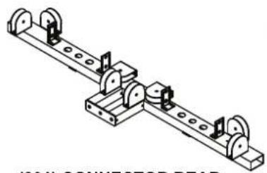
natural_image
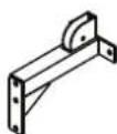
Technical line drawing of a mechanical assembly with rollers and levers (no text or symbols)(201) CONNECTOR REAR STABILIZER
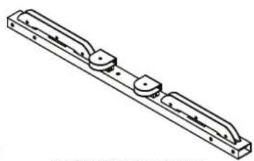
natural_image
Technical line drawing of a mechanical component with flanges and mounting holes (no text or symbols)(202) CONNECTOR REAR TOP FRAME
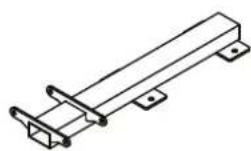
(203) CONNECTOR TOP FRAME
natural_image
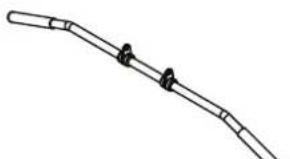
Simple line drawing of a curved pipe or tube with two connectors (no text or symbols)(205) LAT BAR (206) CURL BAR (207) LINK PLATE
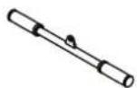

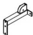
(208L) LEFT
TOP CABLE
CONNECTOR
(209R) RIGHT
TOP CABLE
CONNECTOR

(210) TOP GUIDE
ROD HOLDER
X 2pcs

(211L) LEFT PULLEY HEIGHT ADJUSTER
(204) GUIDE
ROD X 4pcs

(212R) RIGHT PULLEY
HEIGHT ADJUSTER

(213) PULLEY BLOCK X 2pcs
natural_image
Five technical illustrations of mechanical parts: a box, hook, cylindrical rod, washer, and clamped bracket (no text or symbols)(235) 45 X 75mm
END CAP X 2pcs
(240) SNAP
HOOK X 6pcs
(241) SELECTOR PIN X 2pcs
(247) RUBBER CUSHION X 4pcs
(248) PLASTIC GUIDE
ROD HOLDER X 4pcs
(272) HOOK PLATE

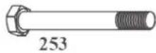
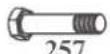


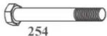
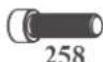
NO. DESCRIPTION QTY.
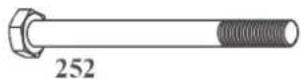
| 252 | 1/2" X 6" HEX BOLT (PRE-MOUNTED) | 2 |
| 253 | 1/2" X 4-1/2" HEX BOLT | 2 |
| 254 | 1/2" X 4-1/4" HEX BOLT | 8 |
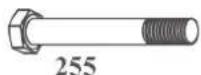
| 255 | 1/2" X 3-3/4" HEX BOLT | 2 |
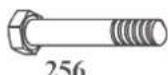
| 256 | 1/2" X 3" HEX BOLT | 12 |
| 257 | 3/8" X 1-3/4" HEX BOLT | 34 |
| 258 | TOP PLATE BOLT | 2 |
| 261 | 5/16" X 1/2" HEX THREADED BOLT | 8 |
| 265 | 1/2" SMALLER WASHER | 8 |
| 266 | 1/2" LARGER WASHER | 42 |
| 267 | 5/16" WASHER | 8 |
| 268 | 1/2" NYLON NUT | 24 |
| 269 | 3/8" NYLON NUT | 32 |
2.3 Assembly
Before assembly, take a close look at the individual assembly steps shown and carry out the assembly in the order given.
i NOTICE
First loosely screw all parts together and check that they fit properly. Tighten the screws using the tool only when you are instructed to do so.
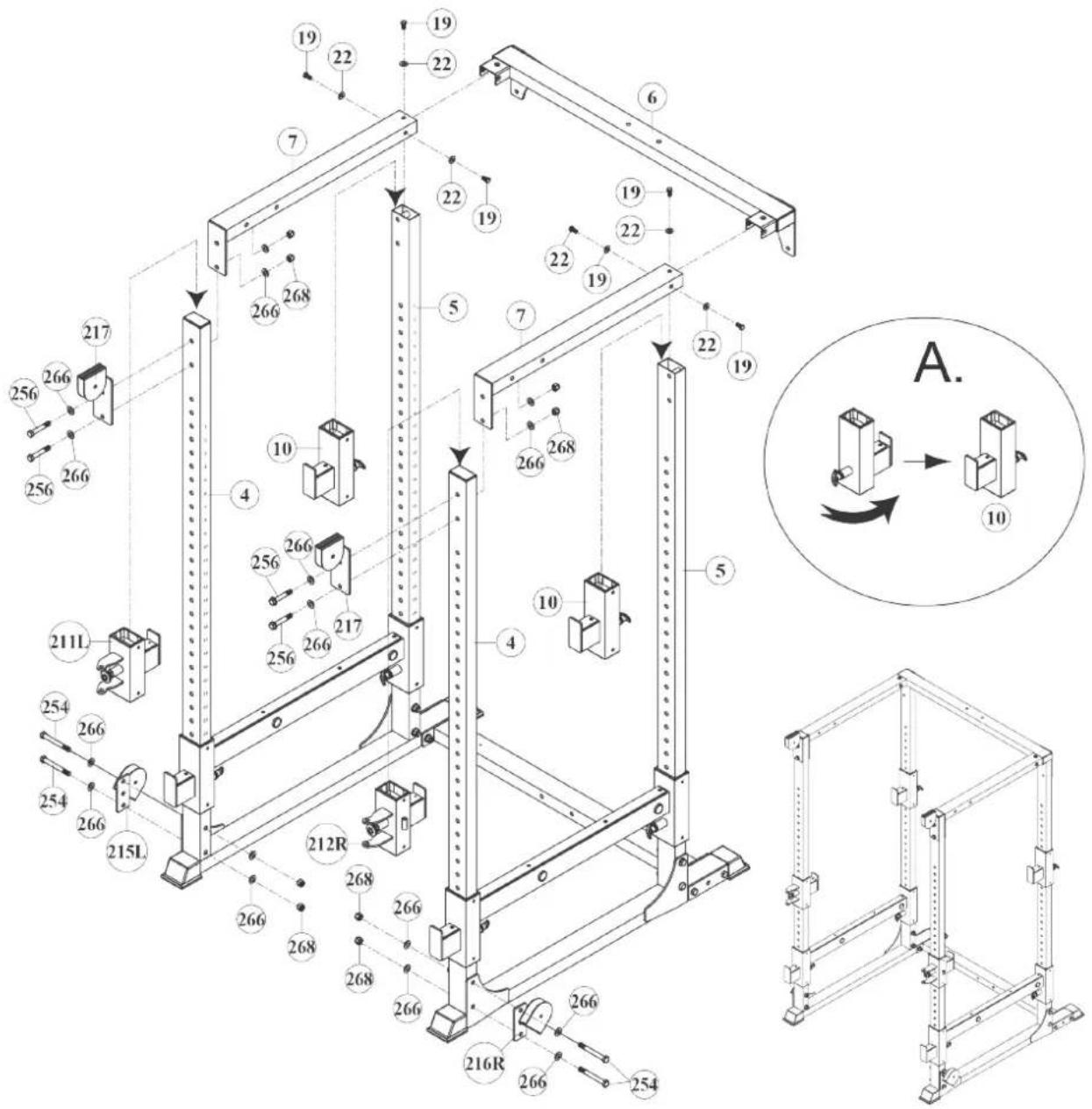
Step 1: Mounting the height adjuster
- Remove the bolts, washers and nuts from the already mounted top frame (6 & 7) and remove the top frame.
Keep the bolts, washers and nuts that were attached to the rear uprights. They will be needed again. - Remove the Bar Catch (10) from the front support (4) and slide each one Bar Catch (10) over the rear uprights (5) with the adjusting knob pointing downwards (Fig. A).
- Slide the height adjuster (211L & 212 R) onto the respective front support (4).
- Remount the top frame (6 & 7) to the rear uprights (5) with the bolts, washers and nuts removed previously.
- Mount the top frame (7) to the front uprights (4) along with the pulley connector plates (217) using a total of four 1/2" X 3" Hex Bolts (256), eight 1/2" Larger Washers (266) and four 1/2" Nylon Nuts (268).
- Mount the left & right Pulley Connector Plate (215L & 216R) to the outside of the front upright (4) using a total of 1/2" X 4" Hex Bolts (254), eight 1/2" Larger Washers (266) and four 1/2" Nylon Nuts (268).
- Tighten all bolts and nuts.
ATTENTION
text_image
Technical schematic diagram of a mechanical assembly with numbered components and a magnified view labeled A.Step 2: Assembly of the connector top frame
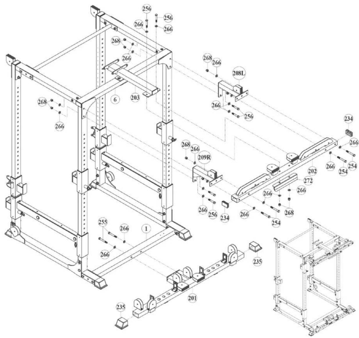
- Place two 45 X 75mm Plugs (234) on the ends of the Connector Top Frame (203).
- Mount the Connector Top Frame (203) to the Rear Top Frame (6) along with the Link Plate (207) using a total of two 3/8" X 2-3/4" Hex Bolts (256), four 1/2" Larger Washers (266) and two 1/2" Nylon Nuts (268).
- Tighten all bolts and nuts.

text_image
Technical diagram of a mechanical frame assembly with numbered components and structural details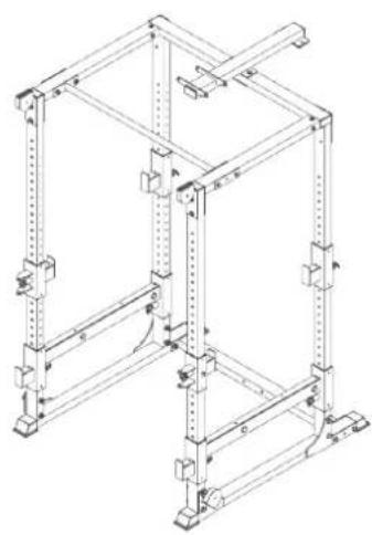
natural_image
Technical line drawing of a structural frame with vertical supports and mounting brackets (no text or symbols)Step 3: Assemble the connector rear top frame
- Place two 45 X 75mm End Caps (235) on the ends of the Connector Rear Stabilizer (201) and mount the Connector Rear Stabilizer (201) to the Rear Stabilizer (1) using two 1/2" X 3-3/4" Hex Bolts (255) and two 1/2" Larger Washers (266)
- Mount the Left & Right Top Cable Connector (208L & 209R) to the Connector Rear Top Frame (202) using a total of four 1/2" X 4" Hex Bolts (254), eight 1/2" Larger Washers (266) and four 1/2" Nylon Nuts (268).
- Mount the Connector Rear Top Frame (202) to the rear uprights using a total of four 1/2" X 3" Hex Bolts (256), eight 1/2" Larger Washers (266) and four 1/2" Nylon Nuts (268).
- Mount the Connector Rear Top Frame (202) along with the Hook Plate (272) to the Connector Top Frame (203) using two 1/2" X 3" Hex Bolts (256), four 1/2" Larger Washers (266) and two 1/2" Nylon Nuts (268).
- Tighten all bolts and nuts.
text_image
Technical schematic diagram of a mechanical assembly with numbered components and labeled partsStep 4: Assembly of the weight blocks
ATTENTION
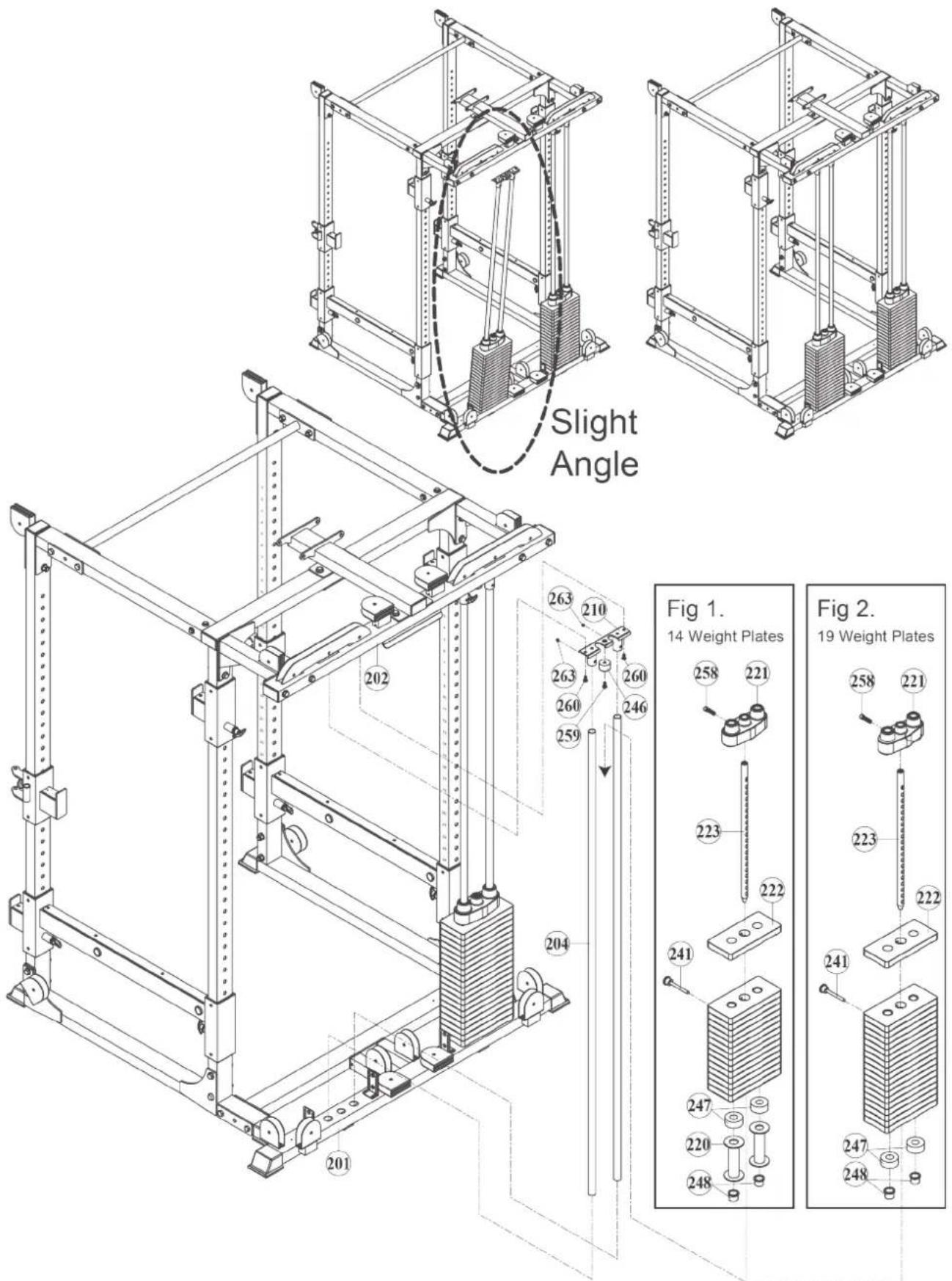
If your weight block consists of 19 weight plates, do not install the Stack Spacers (220) (fig. 1&2).
- If your weight block has 14 Weight Plates (222) each, slide the Stack Spacers (220) over each Guide Rod (204) (fig. 2).
- Slide one Rubber Cushion over each Guide Rod (204) and insert the Guide Rod Holders (288) to the respective slots of the Connector Rear Stabilizer (201).
- Insert the Guide Rods (204) into the Guide Rod Holders (248).
- Slightly tilt the Guide Rods (204) and slide the Weight Plates (222) over the Guide Rods (204).
ATTENTION
Make sure that the selector holes on the weight plates are facing down and point forward.
- Mount the Top Plate (221) to the Selector Rod (223) using the Top Plate Bolt (258) and tighten the bolt.
- Insert the Selector Rod (223) through the opening of the weight blocks.
- Mount the Top Plate Guide Rod Holder (210) to the Guide Rods (205) using the four 5/16" X 1/4" Inner Hex Screws (263).
- Mount the Top Plate Guide Rod Holders (210) along with the Guide Rods (205) to the Connector Rear Top Frame (202) along with the Stopper (246) using a total of four 5/16" X 5/8" Hex Socken Dome Bolts (260) and two 3/8" X 5/8" Hex Socken Dome Bolts (259).
- Insert the Selector Pin (241) in one of the selector holes of the Weight Plates (222).
- Tighten the bolts.
text_image
Slight Angle Fig 1. 14 Weight Plates Fig 2. 19 Weight PlatesStep 5: Assembly of the rotating pulley holder
-
Mount the Top Frame Pulley Brackets (219) to the Top Frame (203) using a total of two 1/2"X 6"Hex Bolts (252), four 1/2" Smaller Washers (265) and two 1/2" Nylon Nuts (268).
-
Mount the Rotating Pulley Holder (218) to the Left & Right Pulley Hight Adjuster (211L & 212R) using a total of two 1/2" X 4-1/2" Hex Bolts (253), four 1/2" Smaller Washers (265) and two 1/2" Nylon Nuts (268).
-
Tighten the bolts.
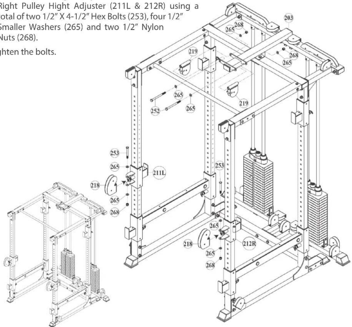
text_image
Right Pulley Hight Adjuster (211L & 212R) using a total of two 1/2" X 4-1/2" Hex Bolts (253), four 1/2" Smaller Washers (265) and two 1/2" Nylon Nuts (268). Bolts Bolts Bolts Bolts Bolts Bolts Bolts Bolts Bolts Bolts Bolts Bolts Bolts Bolts Bolts Bolts Bolts Bolts Bolts Bolts Bolts Bolts Bolts Bolts Bolts BoltsStep 6: Assembly of the top cable
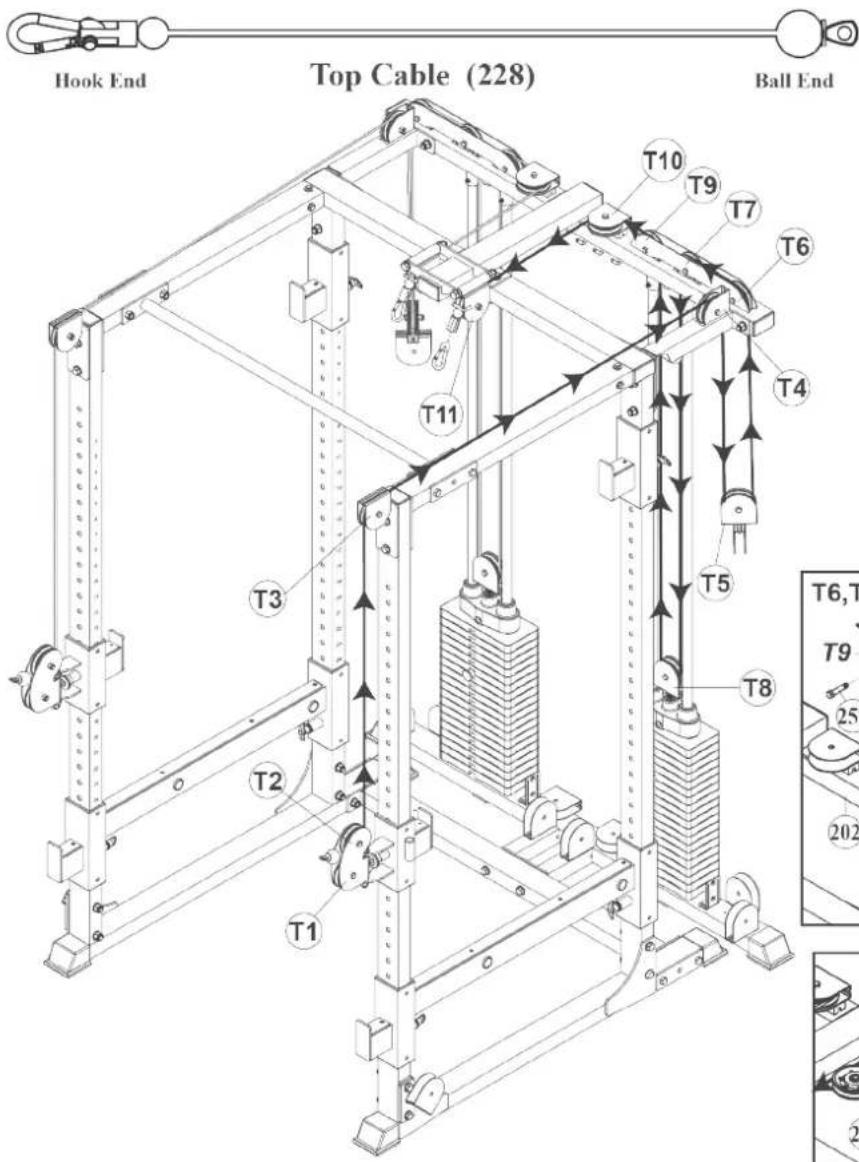
- Fix the Ball End of the Top Cable (228) to the Rotating Pulley Holder (218) on the Pulley Hight Adjuster (211L) with two Pulleys (233). Mount the Pulleys (233) to the points T1 and T2 using each one 3/8" X 1-3/4" Hex Bolt (257) and one 3/8" Nylon Nut (269).
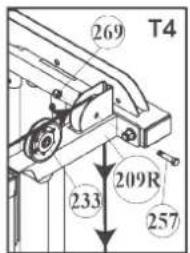
- Guide the cable upwards and along the points T3 and T4. Fix the cable to the points along with each one Pulley (233) using each one 3/8" X 1-3/4" Hex Bolt (257) and one 3/8" Nylon Nut (269).
-
Guide the cable downwards to point T5 and through a Double Pulley Block (214). Fix the cable along with one Pulley (233) using one 3/8" X 1-3/4" Hex Bolt (257) and one 3/8" Nylon Nut (269).
-
Guide the cable along the points T6 and T7. Fix the cable to the points along with each one Pulley (233) using each one 3/8" X 1-3/4" Hex Bolt (257) and one 3/8" Nylon Nut (269).
- Guide the cable downwards to point T8 and screw the Pulley Block (213) at least 1/3 into the slot on the weight block and tighten the nut (270). Guide the cable through the Pulley Block (213) and fix the cable along with one Pulley (233) using one 3/8" X 1-3/4" Hex Bolt (257) and one 3/8" Nylon Nut (269).
- Guide the cable upwards again along the points T9, T10 and T11. Fix the cable to the points with each one Pulley (233) using each one 3/8" X 1-3/4" Hex Bolt (257) and one 3/8" Nylon Nut (269).
- Repeat the steps for the other side.
- Tighten all bolts and nuts.
text_image
Hook End Top Cable (228) Ball End T10 T9 T7 T6 T4 T11 T3 T5 T8 T6,T T9 25 202 T2 T1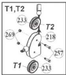
text_image
T1,T2 233 T2 218 269 257 T1 233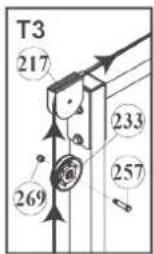
text_image
269 T4 209R 233 257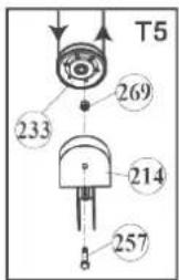
text_image
T5 269 233 214 257
text_image
T6,T7,T9 269 269 257 T7 233 T6 257 202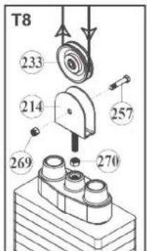
text_image
T8 233 214 257 269 270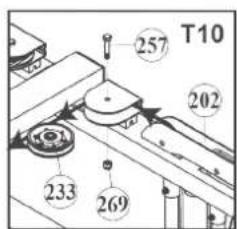
text_image
T10 257 202 233 269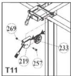
text_image
269 233 219 257 T11Step 7: Assembly of the lower cable
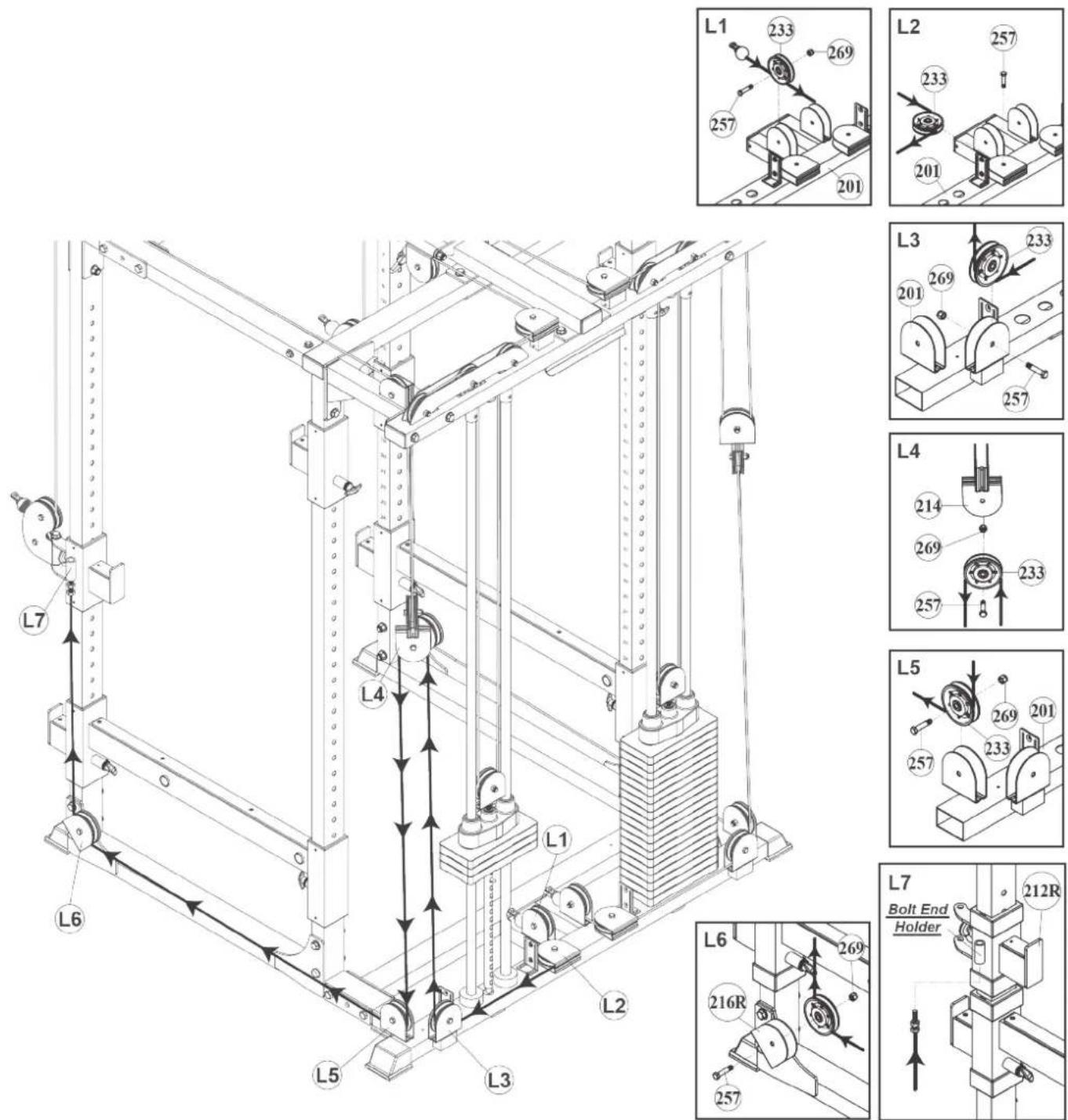
- Fix the Ball End of the Low Cable (229) to the pulley holder on the Connector Rear Stabilizer (201) along with a Pulley (233). Mount the Pulley (233) to the pulley holder at the point L1 using one 3/8" X 1-3/4" Hex Bolt (257) and one 3/8" Nylon Nut (269).
- Guide the cable to point L2 through the rear pulley holder on the Connector Rear Stabilizer (201). Fix the cable along with a Pulley (233) using one 3/8" X 1-3/4" Hex Bolt (257).
- Guide the cable to point L3 through the pulley holder on the Connector Rear Stabilizer (201). Fix the cable along with a Pulley (233) using one 3/8" X 1-3/4" Hex Bolt (257) and one 3/8" Nylon Nut (269).
- Guide the cable upwards to point L4 through the Double Pulley Block (214). Fix the cable along with one Pulley (233) using one 3/8" X 1-3/4" Hex Bolt (257) and one 3/8" Nylon Nut (269).
- Guide the cable downwards and along the points L5 and L6. Fix the cable to the points along with each one Pulley (233) using each one 3/8" X 1-3/4" Hex Bolt (257) and one 3/8" Nylon Nut (269).
- Guide the cable upwards to point L7 and screw the Bolt-End of the cable into the slot of the Pulley Height Adjuster (212R).
- Repeat the steps for the other side.
- Tighten all bolts and nuts.
Step 8: Assembly of the weight panels and accessories
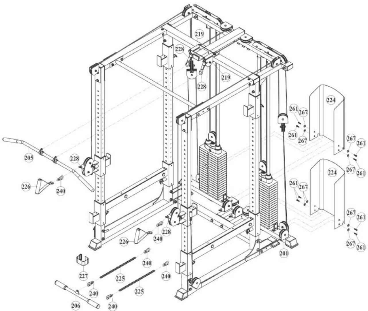
- Mount the two Weight Panels (224) to the Connector Rear Stabilizer (201) using a total of eight 5/16" X 1/4" Hex Socken Dome Bolts (261) and 16 5/16" Washers (267).
- Fix the Lat Bar (205) to the snap hook of the Top Cable (228).
- Fix the two Handles (226) to the Top Cable (228) at the height adjusters using each one Snap Hook (240).
- Fix the Ankle Strap (227) an the Curl Bar (206) to the Low Cable (229) using one Snap Hook (240).
i NOTICE
Alternatively, a Chain (225) can be attached between two snap hooks (240) for extension.
- Finally, make sure that all bolts and nuts are tightened securely.
text_image
Technical diagram of a mechanical lifting system with numbered components and labeled parts3.2 Cable Adjustment
The cables should be tensioned so that the top weight plate is just resting on the other weight plates. As soon as the top weight plate does not rest on the other weight plates, the cable should be extended. As soon as the cable slackens, the cable must be shortened.
- To tension or loosen the cable, first remove the pulley from the pulley block on the weight block.
- Now turn the pulley block further out to loosen the cable or further in to tension the cable.
- Remount the pulley with the cable in the pulley block and tighten the bolts and nuts.
3 STORAGE AND TRANSPORT
3.1 General Instructions

WARNING
+ The storage location should be chosen so that improper use by third parties or children can be prevented.
+ If your equipment does not have transportation wheels, the equipment must be disassembled before transportation.
ATTENTION
+ Make sure that the equipment is protected from moisture, dust and dirt in the selected storage location. The storage location should be dry and well ventilated and have a constant ambient temperature between 10^ C and 35^ C.
4.1 General Instructions
WARNING
+ Do not make any improper changes to the equipment.
CAUTION
+ Damaged or worn components may affect your safety and the life of the equipment. Therefore, immediately replace damaged or worn components. In such a case, contact the contract partner. The equipment must not be used until it has been repaired. If necessary, use only original spare parts.
ATTENTION
+ In addition to the instructions and recommendations for maintenance and care given here, additional service and/or repair work may be necessary; this must only be carried out by authorised service technicians.
4.2 Faults and Fault Diagnosis
The equipment undergoes regular quality controls during production. Nevertheless, faults or malfunctions may occur. Frequently, individual parts are responsible for these disturbances, an exchange is usually sufficient. Please refer to the following overview for the most common errors and how to correct them. If the equipment still does not function properly, contact your contract partner.
| Fault Cause Solution | ||
| Grinding noises | Cables or pulleys do not run smoothly or are damaged | + Visual inspection of the cable routing or the pulley guide+ If damaged, replace the defective part |
| Weight hanging in the air | Cable tensioned too tight Readjust cable tension | |
| Cable without tension | Cable too loose Readjust cable tension | |
| Squeaking & cracking noises | Screw connections loosened or too tight | Check screw connections |
4.3 Maintenance and Inspection Calendar
To avoid damage from body sweat, the equipment must be cleaned with a damp towel (no solvents!) after each training session.
The following routine tasks must be performed at the specified intervals:
| Part Weekly Monthly Quarterly | |||
| Cables C I | |||
| Screw connections I | |||
| Pulleys and cable routing I | |||
| Slide rails/Guide rods I | |||
| Weights I | |||
| Legend: C = clean; I = inspect | |||
5 DISPOSAL
At the end of its operational life, this equipment cannot be disposed of in normal household waste. Instead, it must be disposed of via an recycling centre. Further information can be obtained from your local authority's recycling service.
The materials can be recycled as per their symbols. Through the reuse, recycling of materials or other forms of recovery of old equipment, you make an important contribution to the protection of the environment.
6 RECOMMENDED ACCESSORIES
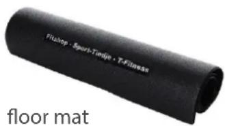
To make your training experience even more efficient and pleasant, we recommend that you add suiting accessories to your fitness equipment. This could be a floor mat, for example, which makes your fitness equipment stand more securely and also protects the floor from falling sweat, but it could also be additional handrails on some treadmills or silicone spray to keep moving parts in good shape.
If you have purchased a fitness machine with pulse training and want to train your heart rate, we strongly recommend that you use a compatible chest strap, as this ensures optimum transmission of the heart rate. You may want to buy additional grips or weights for multi gyms.
Our range of accessories offers the highest quality and makes training even better. If you would like to find out more about compatible accessories, please go to the detail page of the product in our webshop (the easiest way is to enter the article number in the search field above) and go to the recommended accessories on this page. Of course, you can also contact our customer service: by telephone, e-mail, in one of our branches or via our social media channels. We will be happy to advise you!
text_image
Fittop - Sport-Tendje - T-Fitness floor mat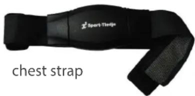
text_image
Sport-Tledge chest strap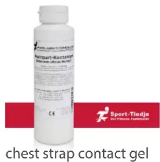
text_image
Sport-part-Kontschutz Sport Tiedje Sport support contact gel C€ chest strap contact gel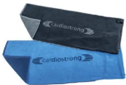
natural_image
Two blue and black textured objects, one with 'cardiostrong' branding, placed side by side (no additional text or symbols visible)
text_image
LOBOSIL SILIKON Taserolol Ostradiol Sport-Tiedje Sylacorel Silicone spray chest strap Sport-Tiedje Sylacoreltowels
7.1 Serial Number and Model Name
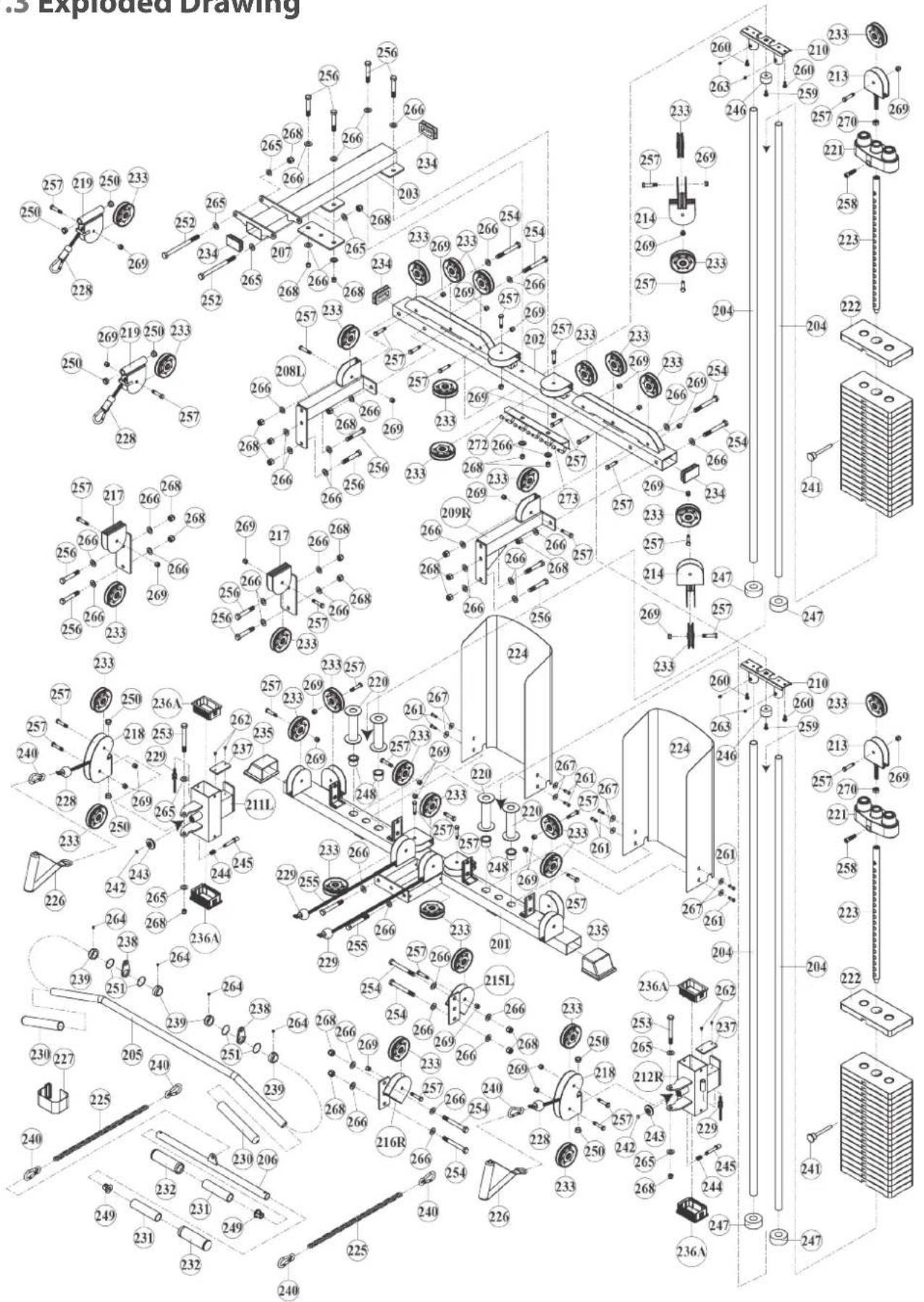
In order to provide you with the best possible service, please have the model name, article number, serial number, exploded drawing and parts list ready. The corresponding contact options can be found in chapter 9 of this operating manual.
NOTICE
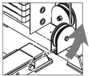
The serial number of your equipment is unique. It's located on a white sticker. The exact position of this sticker is shown in the following illustration.
natural_image
Mechanical assembly diagram showing a pulley system with mounting brackets and a directional arrow (no text or labels)Enter the serial number in the appropriate field.
Serial number:
Brand / Category:
BodyCraft / cable pull
Model Name:
Cable Pull for F430
Article Number:
BC-F438
7.2 Parts List
| No. | Name | Qty. | No. | Name | Qty. |
| 201 | CONNECTOR REAR STABILIZER 1 | 233 | PULLEY 90mm | 34 | |
| 202 | CONNECTOR REAR TOP FRAME 1 | 234 45 | X 75mm PLUG | 4 | |
| 203 | CONNECTOR TOP FRAME 1 | 235 45 | X 75mm END CAP | 2 | |
| 204 | GUIDE ROD 4 | 236 45 | X 75mm HOLLOW BUSHING 4 | ||
| 205 | LAT BAR 1 | 237 | CONNECTOR PLATE | 2 | |
| 206 | CURL BAR 1 | 238 | HOOK PLATE | 4 | |
| 207 | LINK PLATE 1 | 239 | COLLAR 6 | ||
| 208L | LEFT TOP CABLE CONNECTOR 1 | 240 | SNAP HOOK | 2 | |
| 209R | RIGHT TOP CABLE CONNECTOR | 1 | 241 | SELECTOR PIN | 2 |
| 210 | TOP GUIDE ROD HOLDER | 2 | 242 | RUBBER COLLAR | 2 |
| 211L | LEFT PULLEY HEIGHT ADJUSTER | 1 | 243 | PLASTIC WASHER | 2 |
| 212R | RIGHT PULLEY HEIGHT ADJUSTER | 1 | 244 | SPRING | 2 |
| 213 | PULLEY BLOCK | 2 | 245 | PIN BOLT | 2 |
| 214 | DOUBLE PULLEY BLOCK | 2 | 246 | STOPPER | 2 |
| 215L | LEFT PULLEY CONNECTOR PLATE | 1 | 247 | RUBBER CUSHION | 4 |
| 216R | RIGHT PULLEY CONNETCOR PLATE | 1 | 248 | PLASTIC GUIDE ROD HOLDER | 4 |
| 217 | PULLEY CONNECTOR PLATE | 2 | 249 1" | T SHAPE END PLUG | 2 |
| 218 | ROTATING PULLEY HOLDER | 2 | 250 | BUSHING | 8 |
| 219 | TOP FRAME PULLEY BRACKET | 2 | 251 | SEALING RING | 4 |
| 220 | STACK SPACER | 4 | 252 1/2" | X 6" HEX BOLT | 2 |
| 221 | TOP PLATE | 2 | 253 1/2" | X 4-1/2" HEX BOLT | 2 |
| 222 | WEIGHT PLATE | 38 | 254 1/2" | X 4-1/4" HEX BOLT | 8 |
| 223 | SELECTOR ROD | 2 | 255 1/2" | X 3-3/4" HEX BOLT | 2 |
| 224 | STACK GUARDS | 2 | 256 1/2" | X 3" HEX BOLT | 12 |
| 225 | CHAIN | 2 | 257 3/8" | X 1-3/4" HEX BOLT | 34 |
| 226 | SINGLE HANDLE | 2 | 258 | TOP PLATE BOLT | 2 |
| 227 | ANKLE STRAP | 1 | 259 3/8" | X 5/8" HEX SOCKET DOME BOLT | 2 |
| 228 | TOP CABLE (7200mm) | 2 | 260 5/16" | X 5/8" HEX SOCKET DOME BOLT | 4 |
| 229 | LOW CABLE (5980mm) | 2 | 261 5/16" | X 1/4" HEX SOCKET DOME BOLT | 8 |
| 230 1" | X 200mm L HAND GRIP | 2 | 262 M5 | X 15mm TAPPING SCREW | 4 |
| 231 | SLEEVE | 2 | 263 5/16" | X 1/4" INNER HEX SCREW | 4 |
| 232 1- | 1/4 X 130" HAND GRIP | 2 | 264 M6 | X 6mm L INNER HEX SCREW | 4 |
| 265 1/2" SMALLER WASHER 8 | |
| 266 1/2" LARGER WASHER 42 | |
| 267 5/16" WASHER 8 | |
| 268 1/2" NYLON NUT 24 | |
| 269 3/8" NYLON NUT 32 | |
| 270 1/2" NUT 2 | |
| 271 HEX WRENCH 1 | |
| 272 HOOK PLATE 1 |
7.3 Exploded Drawing
text_image
.3 Exploded Drawing 250 219 250 233 257 269 219 250 233 250 266 217 266 268 268 256 266 217 266 268 268 256 266 217 266 268 268 256 266 217 266 268 268 257 266 217 266 268 268 257 266 217 266 268 268 257 266 217 266 268 268 257 266 217 266 268 268 257 264 217 264 264 257 264 217 264 264 257 264 217 264 264 257 264 217 264 264 257 264 217 264 264 257 264 217 264 263 257 264 217 264 264 257 264 217 264 264 257 264 217 264 264 257 264 217 264 257 264 217 257 264 217 257 264 217 257 264 217 257 264 217 257 264 217 257 264 217 257 264 217 257 264 217 258 219 259 219 259 259 259 259 259 259 259 259 259 259 259 259 259 259 259 259 259 259 259 259 259 259 259 259 259 204 100 100 100 100 100 100 100 100 100 100 100 100 100 100 100 100 100 100 100 100 100 100 100 100 100 104 104 104 104 104 104 104 104 104 104 104 104 104 104 104 104 104 104Training equipment from Taurus ^® is subject to strict quality control. However, if a fitness equipment purchased from us does not work perfectly, we take it very seriously and ask you to contact our customer service as indicated. We are happy to help you by phone via our service hotline.
Error Descriptions
Your fitness equipment is developed for long-term, high-quality training. However, should a problem arise, please first read the operating instructions. For further assistance, please contact your contract partner or call our service hotline. To ensure your problem is solved as quickly as possible, please describe the defect as exactly as possible.
In addition to the statutory warranty, we provide a warranty for every fitness equipment purchased from us according to the following provisions.
Your statutory rights are not affected.
Warrantee
The warrantee is the first/original buyer and/or any person who received a newly purchased product as a gift from the original buyer.
Warranty period
The warranty periods, shown on our web shop, begin on delivery of the fitness equipment. The respective warranty periods for your equipment can be found on its product website.
Repair Costs
According to our choice, there will either be a repair, a replacement of individual damaged parts or a complete replacement. Spare parts, that have to be mounted while assembling the equipment, have to be replaced by the warrantee personally and are not a part of repair. After the expiration of the warranty period for repair costs, a pure parts warranty applies, which does not include the repair, installation and delivery costs.
The terms of use are defined as follows:
- Home use: solely for private use in private households up to 3 hours per day
- Semi-professional use: up to 6 hours per day (e. g. rehabilitation centres, hotels, clubs, company gyms)
- Professional use: more than 6 hours per day (e. g. commercial gyms)
Warranty Service
Within the warranty period, equipment which develops faults as a result of material or manufacturing defects, will be repaired or replaced at our discretion. Ownership of equipment or parts of equipment which have been replaced is transferred to us. The warranty period is not extended nor does a new warranty period begin following repair or replacement under the warranty.
Warranty Conditions
For the warranty to be valid, the following steps must be taken:
Please contact our customer service by email or phone. If the product under warranty has to be sent in for repair, the seller bears costs. After expiry of the warranty, the buyer bears the costs of transport and insurance. If the fault is covered by our warranty, you will receive a new or repaired equipment in return.
Warranty claims are invalid in case of damage resulting from:
- misuse or improper handling
- environmental influences (moisture, heat, electrical surge, dust, etc.)
- failure to follow the current safety measures for the equipment
- failure to follow the operating instructions
- use of force (e. g. hitting, kicking, falling)
- interventions which were not carried out by one of our authorized service centres
- unauthorised repair attempts
Proof of Purchase and Serial Number
Please make sure that you are able to provide the appropriate receipt when claiming on your warranty. So that we can clearly identify the model of your equipment, and for the purposes of our quality control, you will need to give the serial number of your equipment, when contacting the service team. Where possible please have your serial number and your customer number ready when you call our service hotline. It will help us to deal with your request swiftly.
If you cannot find the serial number on your fitness equipment, our service team is at your disposal to offer further information.
Service outside of the Warranty Period
We are also happy to issue an individual cost estimate if there is a problem with your fitness equipment after the warranty has expired, or in cases which do not fall under the terms of the warranty, e. g. normal wear and tear. Please contact our customer service team to find a quick and cost-effective solution to your problem. In such a case you will be responsible for the delivery costs.
Communication
Many problems can be solved just by speaking to us as your specialist supplier. We know how important it is to you as a user of the fitness equipment to have problems solved quickly and simply, so you can enjoy working out with minimal interruption. For that reason, we also want to resolve your queries quickly and in a straightforward manner. Thus, please always keep your customer number and the serial number of the faulty equipment handy.
DE DK FR
| TECHNICAL SUPPORT TECHNICAL SUPPORT & SERVICE TECHNICAL SUPPORT & SERVICE | ||
| 80 90 16 50+49 4621 4210-945info@fitshop.dkMo - Fr 08:00 - 18:00Sa 09:00 - 18:00 | +33 (0) 172 770033+49 4621 4210-933service-france@fitshop.frMo - Fr 08:00 - 18:00Sa 09:00 - 18:00 | |
| SERVICE | PL | BE |
| 0800 20 20277(Freecall)info@sport-tiedje.deMo - Fr 08:00 - 21:00Sa 09:00 - 21:00So 10:00 - 18:00 | TECHNICAL SUPPORT & SERVICE TECHNICAL SUPPORT & SERVICE22 307 43 21+49 4621 42 10-948info@fitshop.plMo - Fr 08:00 - 18:00Sa 09:00 - 18:00 | 02 732 46 77+49 4621 42 10-932info@fitshop.beMo - Fr 08:00 - 18:00Sa 09:00 - 18:00 |
| UK | NL | INT |
| TECHNICAL SUPPORT+44 141 876 3986support@powerhousefitness.co.ukSERVICE+44 141 876 3972Mo - Fr 9am - 5pm | TECHNICAL SUPPORT & SERVICE+31 172 619961info@fitshop.nlMa - Do 09:00 - 17:00Vr 09:00 - 21:00Za 10:00 - 17:00 | TECHNICAL SUPPORT & SERVICE+49 4621 4210-944service-int@sport-tiedje.deMo - Fr 8am - 6pmSat 9am - 6pm |
| AT | CH | |
| TECHNICAL SUPPORT & SERVICE0800 20 20277(Freecall)+49 4621 42 10-0info@sport-tiedje.atMo - Fr 08:00 - 18:00Sa 09:00 - 18:00 | TECHNICAL SUPPORT & SERVICE0800 202 027+49 4621 42 10-0info@sport-tiedje.chMo - Fr 08:00 - 18:00Sa 09:00 - 18:00 |
Please find a detailed overview including address and opening hours for all stores of the Sport-Tiedje Group in Germany and abroad on the following website:
www.sport-tiedje.com/en/stores
WE LIVE FITNESS
WEBSHOP AND SOCIAL MEDIA
Sport-Tiedje is Europe's largest specialist store for home fitness equipment with currently over 70 stores and one of the world's most renowned online mail order companies for fitness equipment. Private customers order via the 25 web shops in the respective national language or have their desired equipment assembled on site. In addition, the company supplies fitness studios, hotels, sports clubs, companies and physio practices with professional equipment for endurance and strength training.
Sport-Tiedje offers a wide range of fitness equipment from renowned manufacturers, high-quality in-house developments and comprehensive services, such as a build-up service and sports scientific advice before and after the purchase. The company employs numerous sports scientists, fitness trainers and competitive athletes.
Visit us also on our social media platforms or our blog!
flowchart
graph TD
    A["www.sport-tiedje.co.uk\nwww.sport-tiedje.de/blog"] --> B["f"]
    B --> C["www.facebook.com/SportTiedje"]
    C --> D["www.instagram.com/sporttiedje"]
    D --> E["www.youtube.com/user/sporttiedje"]
    E --> F["TAURUS"]
    F --> G["cardiostrong"]
    G --> H["BODYCRAFT"]
    H --> I["cardiojump"]
    I --> J["DUKEFITNESS"]
    J --> K["DARWIN"]