
Super Gym 1 - Fitness Equipment BodyCraft - Free user manual and instructions
Find the device manual for free Super Gym 1 BodyCraft in PDF.


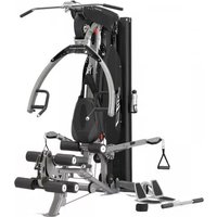
| Product Type | Multi-functional Home Gym |
| Brand | BodyCraft |
| Model | Super Gym 1 |
| Dimensions (L x W x H) | Approx. 90 x 50 x 84 inches |
| Weight | Approx. 450 lbs |
| Maximum User Weight | 300 lbs |
| Weight Stack | 210 lbs (two 100 lb stacks + 10 lb increments) |
| Resistance Type | Weight stack with selectorized pin |
| Number of Exercises | Over 30 exercises |
| Pulley System | High and low pulley with 2:1 ratio |
| Frame Material | Heavy-gauge steel tubing |
| Seat Adjustment | Multi-position adjustable seat |
| Backrest Adjustment | Adjustable back support |
| Leg Press | Integrated leg press platform |
| Chin-up Bar | Dual grip chin-up station |
| Warranty | Lifetime frame, 1 year parts |
| Maintenance | Lubricate guide rods and cables biannually; check bolts monthly |
| Cleaning | Wipe with damp cloth, avoid solvents |
| Safety Features | Weight stack shrouds, user weight limit, instruction decals |
| Spare Parts | Available through authorized dealers; cables, pulleys, and pins |
| Repairability | Modular design; most parts user-serviceable with basic tools |
Frequently Asked Questions - Super Gym 1 BodyCraft
User questions about Super Gym 1 BodyCraft
0 question about this device. Answer the ones you know or ask your own.
Ask a new question about this device
Download the instructions for your Fitness Equipment in PDF format for free! Find your manual Super Gym 1 - BodyCraft and take your electronic device back in hand. On this page are published all the documents necessary for the use of your device. Super Gym 1 by BodyCraft.
USER MANUAL Super Gym 1 BodyCraft
Assembly and Operating Instructions
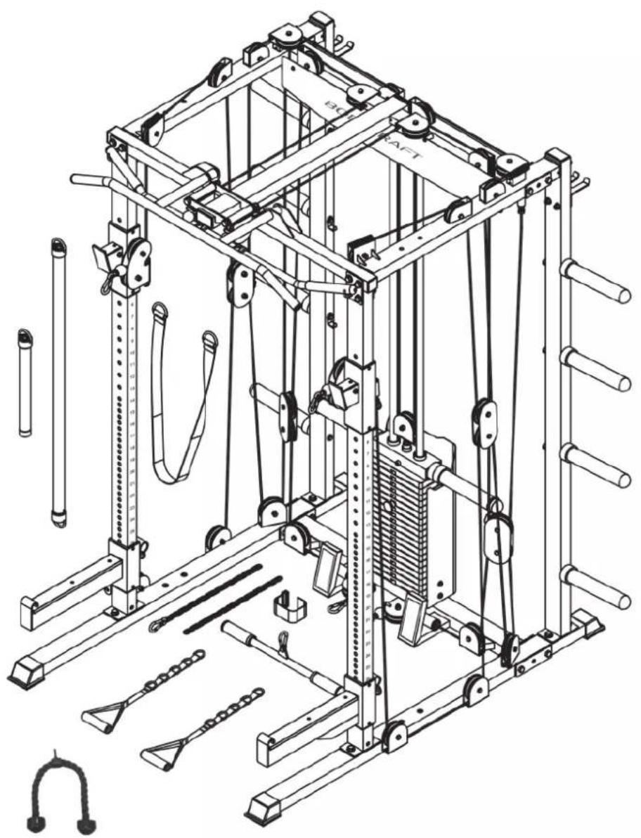
natural_image
Technical line drawing of a 3D mechanical exercise machine with pulleys, weights, and a spring mechanism (no text or labels)Art. No. BC-SG1

BCSG1.01.01
Content
1 GENERAL INFORMATION 7
1.1 Technical Data 7
1.2 Personal Safety 8
1.3 Set-Up Place 9
2 ASSEMBLY 10
2.1 General Instructions 10
2.2 Scope of Delivery 11
2.3 Assembly 14
3 STORAGE AND TRANSPORT 31
3.1 General Instructions 31
4 TROUBLESHOOTING, CARE AND MAINTENANCE 32
4.1 General Instructions 32
4.2 Faults and Fault Diagnosis 32
4.3 Maintenance and Inspection Calendar 33
5 DISPOSAL 33
6 RECOMMENDED ACCESSORIES 34
7 ORDERING SPARE PARTS 35
7.1 Serial Number and Model Name 35
7.2 Parts List 36
7.3 Exploded Drawing 40
8 WARRANTY 41
9 CONTACT 43
Dear customer,
Thank you for choosing Bodycraft training equipment. Bodycraft equipment inspires with its multifunctionality and excellent workmanship and is one of the highest quality fitness equipment for home use in terms of innovation and technology. BodyCraft weight stations, for example, offer a very wide range of exercise possibilities. This ranges from traditional strength training such as bench presses to rehabilitation exercises and workouts for complex sports such as golf, tennis or badminton. Further information can be found at www.sport-tiedje.com.
Intended Use
The equipment may only be used for its intended purpose.
The equipment is suitable for home use and semi-professional use (e.g. hospitals, clubs, hotels, schools, etc.). The equipment is not suitable for commercial or professional use (e.g. fitness studio).
Disclaimer
BODYCRAFT
BodyCraft ^® is a registered brand of the company Fitness Authority Industrial Co., LTD. All rights reserved. Any use of this trademark without the explicit written permission of Fitness Authority Industrial Co., LTD is prohibited.
Product and manual are subject to change. Technical data can be changed without advance notice.
ABOUT THIS MANUAL
Please carefully read the entire manual before installation and first use. The manual will help you to quickly set up the system and explains how to safely use it. Make sure that all persons exercising with the equipment (especially children and persons with physical, sensory, mental or motor disabilities) are informed about this manual and its contents in advance. In case of doubt, responsible persons must supervise the use of the equipment.
Due to ongoing changes and software optimisations, the manual may have to be updated. If you notice any discrepancies during assembly or use, please refer to the manual uploaded to the webshop. The latest manual is always available there.
This equipment has been manufactured according to the latest safety knowledge. As far as possible, potential safety hazards which could cause injury have been eliminated. Make sure to carefully follow
the instructions and that all parts are securely in place. If required, read through the instructions again to correct any mistakes.
Please pay close attention to the safety and maintenance instructions given here. The contract partner cannot be held liable for damage to health, accidents or damage to the equipment when it is not used in accordance with these instructions.
The following safety instructions may appear in this manual:
ATTENTION
This notice indicates potentially hazardous situations which, if not avoided, may result in property damage.
CAUTION
This notice indicates potentially hazardous situations which, if not avoided, may result in slight or minor injuries!
WARNING
This notice indicates potentially hazardous situations which, if not avoided, may result in death or serious injuries!
DANGER
This notice indicates potentially hazardous situations which, if not avoided, will result in death or serious injuries!
i NOTICE
This notice indicates further useful information.
Retain these instructions in a safe place for future reference, maintenance or when ordering replacement parts.
1.1 Technical Data
Weight and Dimensions
Weight block (67.5 kg)
Packaging dimensions (L x W x H) and article weight (gross, incl. packaging):
Box 1: 205.7 cm x 36.4 cm 13.3 cm 53.7 kg
Box 2: 160.2 cm x 62.4 cm x 26.1 cm 53.3 kg
Box 3: 94.8 cm x 59.1 cm x 20 cm 55.6 kg
Box 4: 26.9 cm x 20.3 cm x 12.7 cm 32 kg
Box 5: 26.9 cm x 20.3 cm x 12.7 cm 32 kg
Article weight (net, excl. packaging): 149.9 kg / 212.9 kg incl. weight stacks
Set-up dimensions (L x W x H) approx.: 165.6 cm x 182.8 cm x 211.5 cm
Weight block (90 kg)
Packaging dimensions (L x W x H) and article weight (gross, incl. packaging):
Box 1: 205.7 cm x 36.4 cm 13.3 cm 53.7 kg
Box 2: 160.2 cm x 62.4 cm x 26.1 cm 53.3 kg
Box 3: 94.8 cm x 59.1 cm x 20 cm 55.6 kg
Box 4: 26.9 cm x 20.3 cm x 12.7 cm 32 kg
Box 5: 26.9 cm x 20.3 cm x 12.7 cm 32 kg
Box 6: 26.6 cm x 13.6 cm x 13.6 cm 23 kg
Article weight (net, excl. packaging): 149.9 kg/235.4 kg incl. weight stacks
Set-up dimensions (L x W x H) approx.: 165.6 cm x 182.8 cm x 211.5 cm
Quantity of weight stacks: 2
Quantity of weight plates: 14 + 1 / 19 + 1
Weight of one weight plate: 4.5 kg
Cable material: Steel
Cover material: Plastic
Cable length: 986 cm, 429.5 cm, 580.5 cm
Cable width: 0.5 cm, 0.5 cm, 0.5 cm
Pulley diameter: 90 mm
Transmission ratio: 2:1
Maximum user weight (dip bar, chin-up bar): 150 kg
Class:
1.2 Personal Safety

DANGER
- Before you start using the equipment, you should consult your physician that this type of exercise is suitable for you from a health perspective. Particularly affected are persons who: have a hereditary disposition to high blood pressure or heart disease, are over the age of 45, smoke, have high cholesterol values, are overweight and/or have not exercised regularly in the past year. If you are under medical treatment that affects your heart rate, medical advice is absolutely essential.
- Note that excessive training can seriously endanger your health. Please also note that heart rate monitoring systems can be inaccurate. If you notice any signs of weakness, nausea, dizziness, pain, shortness of breath, or other abnormal symptoms, stop exercising immediately and seek advice from your doctor if necessary.
- The owner must communicate all warnings and instructions to the user.

WARNING
- This equipment may not be used by children under the age of 14.
- Children should not be allowed unsupervised access to the equipment.
+ Persons with disabilities must have a medical license and must be under strict observation when using the equipment.
+ The equipment is strictly for use by one person at a time.
- If your equipment provides a safety key, the clip of the safety key must be attached to your clothing before starting your training. In the event of a fall, the EMERGENCY STOP of the equipment can be initiated.
- Keep your hands, feet and other body parts, hair, clothing, jewellery and other objects well clear of moving parts.
- During use, wear suitable sports clothing rather than loose or baggy clothing. When wearing sports shoes, make sure they have suitable soles, preferably made of rubber or other non-slip materials. Shoes with heels, leather soles, studs or spikes are unsuitable. Never exercise barefoot.
+ Always start each workout with a light warm-up and end with a cool-down phase.
+ Using the machine as a support during stretching exercises or attaching resistance bands, ropes or other accessories to it, may cause injuries.

CAUTION
- If your equipment needs to be connected to the power supply with a mains cable, make sure that the cable is not a potential tripping hazard.
- Make sure that nobody is within the range of motion of the equipment during training so as not to endanger you or other persons.
- Be aware that if adjustment devices are left protruding, they may impede the user's movement.

ATTENTION
+ Do not insert any objects of any kind into the openings of the device.
1.3 Set-UpPlace

WARNING
+ Do not place the equipment in main corridors or escape routes.

CAUTION
- Choose a location in which to place the equipment such that there is enough free space/clearance to the front, the rear and to the sides of the equipment.
- The training room should be well ventilated during training and not be exposed to any draughts.
- Choose the place in which to set up the equipment such that there is enough free space/clearance to the front, the rear and to the sides of the equipment.
- The free area in the direction from which the exercise equipment is accessed must be at least 0.6 m larger than the exercise area.
- The set-up and mounting surface of the equipment should be flat, loadable and solid.
- If your device is to be mounted on the wall/ceiling, make sure that you use the appropriate assembly material to avoid possible damages or personal injuries. The contractual partner accepts no liability for this.

ATTENTION
- The device may only be used in one building, in sufficiently tempered and dry rooms (ambient temperatures between 10°C and 35°C). The equipment should not be used outdoors or in rooms with high humidity (over 70%) like swimming pools.
- A floor protective mat/equipment underlay can help to protect high-quality floor coverings (parquet, laminate, cork, carpets) from dents and sweat and can help to level out slight unevenness.
- For Class S and I equipment, the exercise equipment may only be used in areas where access, supervision and control are specifically regulated by the owner.

2.1 GeneralInstructions
DANGER
+ Do not leave any tools, packaging materials such as foils or small parts lying around, as otherwise there is a danger of suffocation for children. Keep children away from the equipment during assembly.
WARNING
+ Pay attention to the instructions attached to the equipment in order to reduce the risk of injuries.
CAUTION
- Ensure to have sufficient room for movement in each direction during assembly.
- The assembly of the equipment must be carried out by at least two adults. If in doubt, seek the help of a third technically skilled person.
ATTENTION
+ To prevent damage to the equipment and the floor, assemble the equipment on a mat or packaging board.
i NOTICE
- In order to make the assembly as simple as possible, some screws and nuts to be used can already be pre-assembled.
- Ideally, assemble the equipment at its later set-up place.
2.2 Scope of Delivery
The scope of delivery consist of the following parts. At the beginning, check whether all parts and tools belonging to the device are included in the scope of delivery and whether damage has occurred. In the event of complaints, the contractual partner must be contacted directly.

CAUTION
If parts of the scope of delivery are missing or damaged, the assembly must not be carried out.

natural_image
Technical line drawing of a mechanical support structure with mounting brackets and wheels (no text or symbols)(1) BASE FRAME
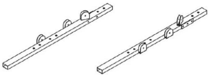
natural_image
Two technical line drawings of a mechanical rail system with pulleys and mounting brackets (no text or symbols)(2L) LEFT BASE FRAME
(3R) RIGHT BASE FRAME

(4) FRONT UPRIGHT FRAME X 2pcs

(5) REAR UPRIGHT FRAME X 2pcs

(6) GUIDE ROD X 2pcs
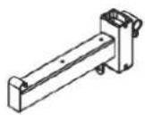
(7L) LEFT SAFETY ARM
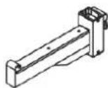
(8R) RIGHT SAFETY ARM

(9L) LEFT
PULLEY HEIGHT
ADJUSTER

(10R) RIGHT
PULLEY HEIGHT
ADJUSTER

(12) CHIN UP FRAME
natural_image
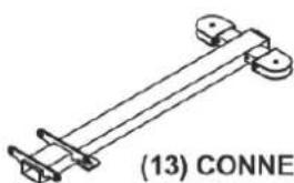
Technical line drawing of a mechanical bracket or support structure (no text or symbols)(13) CONNECTOR TOP FRAME

(14) TOP PANEL

(15L) LEFT
TOP FRAME
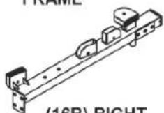
(16R) RIGHT
TOP FRAME

(17) STACK
GUARDS
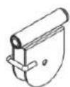
(18) TOP FRAME
PULLEY BRACKET
X 2pcs
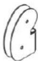
(20) ROTATING PULLEY HOLDER X 2pcs

(21) PULLEY BLOCK

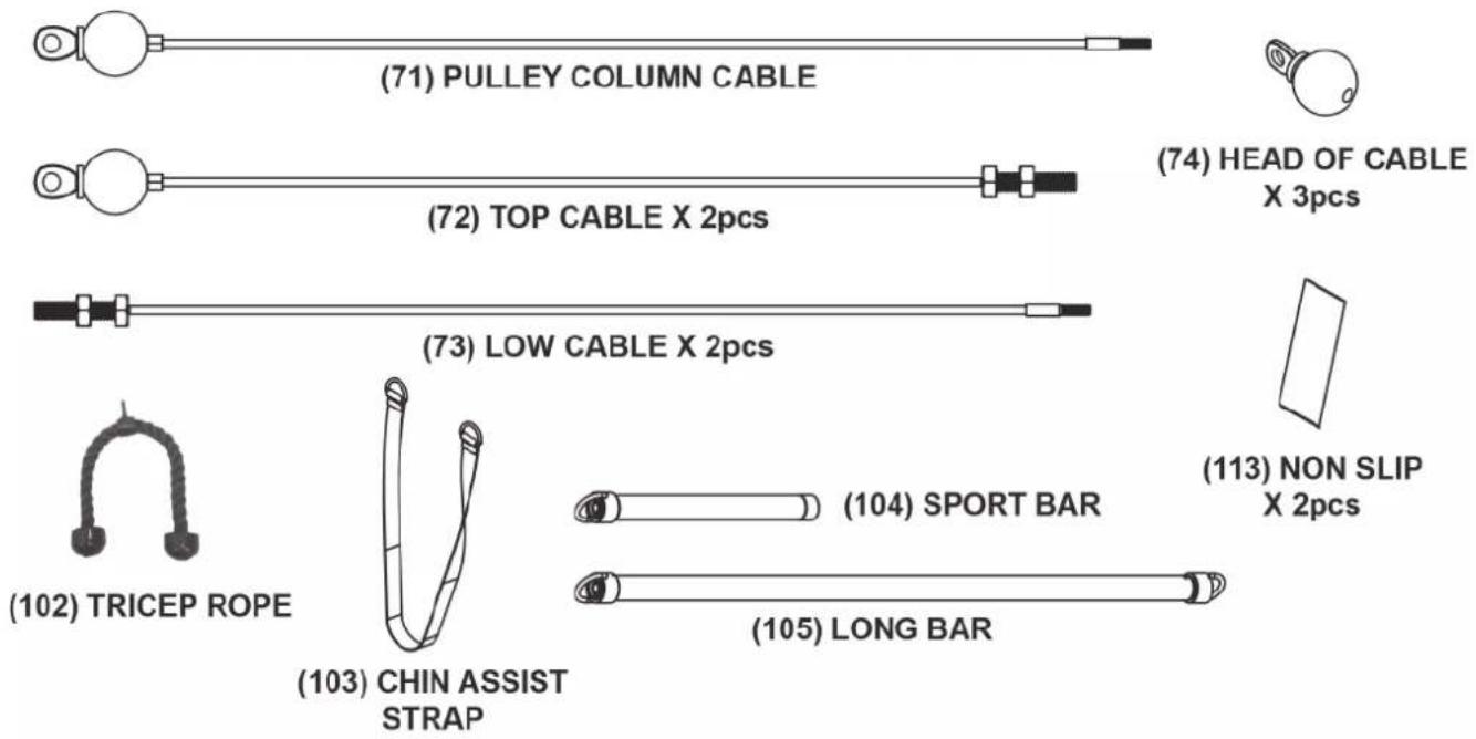
NO. DESCRIPTION QTY.
75 1/2" X 6" HEX BOLT 2
76 1/2" X 4-1/4" HEX BOLT 10
78 1/2" X 3" HEX BOLT 8
79 1/2" X 2-3/4" HEX BOLT 6
81 3/8" X 2-1/2" HEX BOLT 4
82 3/8" X 1-3/4" HEX BOLT 37
85 TOP PLATE BOLT 1
88 M6 X 40L HEX SOCKEN DOME BOLT 4
94 1/2" WASHER 42
95 3/8" WASHER 8
97 1/2" NYLON NUT 16
99 3/8" THICKER NYLON NUT 41

bar
| Item | Value | |---|---| | Top Bar | 75 | | Bottom Bar | 76 | | Middle Bar | 78 | | Bottom Left Bar | 79 | | Bottom Right Bar | 81 | | Top Right Bar | 82 | | Top Left Bar | 85 | | Top Right Bar | 88 | | Bottom Left Ring (Cylinder) | 94 | | Bottom Middle Ring (Cylinder) | 95 | | Bottom Right Ring (Cylinder) | 97 | | Bottom Right Ring (Nylon) | 99 |2.3 Assembly
Before assembly, take a close look at the individual assembly steps shown and carry out the assembly in the order given.
i NOTICE
- First loosely screw all parts together and check that they fit properly. Tighten the screws using the tool only when you are instructed to do so.
- If you have difficulty recognising the graphics, we recommend that you open and/or download the PDF instructions stored in the webshop on your end device (e.g. smartphone, tablet or PC). There you have the option of zooming in closer. Please note that the Adobe Acrobat Reader programme must be installed on your end device in order to open the file.
Step 1: Assembly of the Base Frame
- Attach four end caps (36) to the left and right base frame (2L & 3R).
- Attach two plugs (38) to the base frame (1).
- Assemble the left and right base frame (2L & 3R) to the base frame (1) with four bolts (76), eight washers (94) and four nuts (97).
- Attach two non slips (113) to the base frame (1).

Step 2: Assembly of the Upright Frame
- Attach two plugs (37) to the rear upright frames (5).
- Assemble two rear upright frames (5) to the left and right base frames (2L & 3R) with four bolts (80) and four washers (94).
- Assemble two front upright frames (4) to the left and ight base frames (2L & 3R) with four bolts (80) and four washers (94).
- Slide the left and right safety arms (7L & 8R) to the front upright frames (4).
- Slide the left and right pulley height adjusters (9L & 10R) to the front upright frames (4).
- Assemble two rotating pulley holders (20) to the left and right pulley height adjuster (9L & 10R) with two bolts (76), four washers (94) and two nuts (97).

Step 3: Assembly of the Top Frame
- Assemble the lat bar bracket (23) to the front upright frame (4) and left top frame (15L) with two bolts (78), four washers (94) and two nuts (97).
- Assemble the rear upright frame (5) to the left top frame (15L) with two bolts (79) and two washers (94).
- Assemble the lat bar bracket (23) to front upright frame (4) and right top frame (16R) with two hex bolts (78), four washers (94) and two nuts (97).
- Assemble the rear upright frame (5) to the right top frame (16R) with two bolts (79) and two washers (94).

Step 4: Assembly of the Rear Top Frame & Chin Up Frame
- Attach two plugs (39) to the chin up frame (12).
- Assemble the chin up frame (12) to the left and right top frame (15L & 16R) with four bolts (78) and four washers (94).
- Assemble the rear top frame (11) to the left and right top frame (15L & 16R) with four bolts (76), six washers (94) and two nuts (97).

Step 5: Assembly of the Connector Top Frame
-
Assemble two top frame pulley brackets (18) to the connector top frame (13) with two bolts (75), four washers (94) and two nuts (97).
-
Assemble the connector top frame (13) to the chin up frame (12) and rear top frame (11) with two bolts (79), one bolt (80), fi ve washers (94) and two nuts (97).
-
Attach one plug (37) to the connector top frame (13).

Step 6: Assembly of the Guide Rods and Weight Plates
150 lbs Stack
If you have 14 weight plates (35) per stack, assemble the stack spacers (34) onto each of the guide rods (6), see Fig. 2.
200 lbs Stack
If you have 19 weight plates (35) per stack, DO NOT assemble the stack spacers (34), see Fig. 3.
- Assemble the two way top plate (32) to the the selector rod (29) with one bolt (85) and tighten the bolt.
- Attach the plastic guide rod holders (44) to the base frame (1) and insert the guide rods (6).
- Hold the two guide rods (6) in a slight angle like shown in Fig. 1.
i NOTICE
When assembling the weight plates (35), make sure that each plate is oriented with the selector hole opening on the bottom and facing forward.
3.1. If you have 14 weight plates (35): Slide two stack spacers (34), two rubber cushions (45) and the weight plates (35) one at a time onto the guide rods (6) (see figure 2).
3.2. If you have 19 weight plates (35): Slide two rubber cushions (45) and the weight plates (35) one at a time onto the guide rods (6) (see figure 3).
4. Attach the top guide rod holder (33) onto the guide rods (6) and tilt the guide rods (6) to the upright position.
5. Assemble the top guide rod holder (33) to the rear top frame (11) with two bolts (87).
6. Assemble the two screws (93) to the guide rods (6).
7. Insert the selector pin (59) into any desired hole of the weight stack.


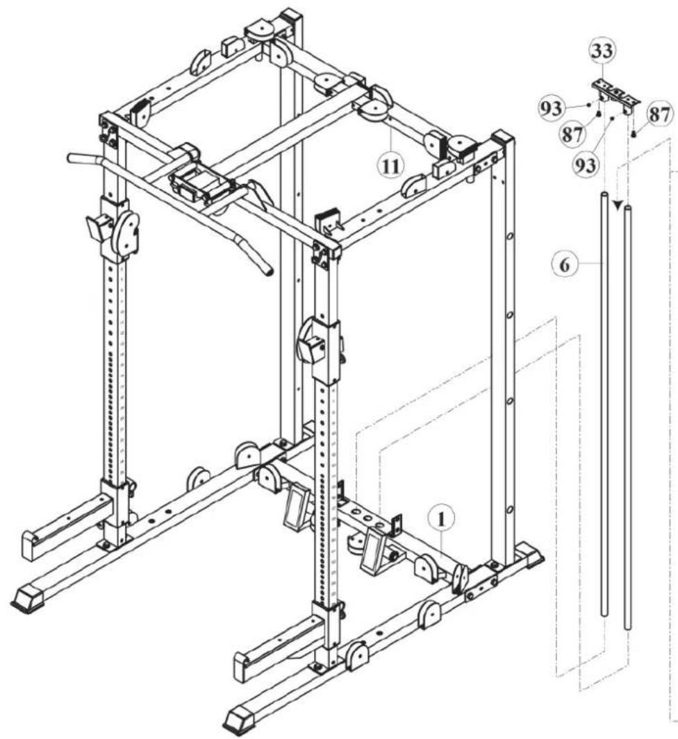

200 lbs stack
i NOTICE
Assemble the pulleys and cables simultaneously.
- Assemble two pulleys (62) to the pulley holder of the left pulley height adjuster (9L) with two bolts (82) and two nuts (99) [T1 & T2].
- Insert the bolt end of the cable (71) into the left pulley height adjuster (9L) and pull it upwards [T1 & T2].
- Assemble two pulleys (62) to the left top frame (15L) with one bolt (82) and one nut (99) each and route the cable (71) over the pulleys [T3 & T4].
- Assemble one pulley (62) between two double cable retainer plates (22) with one bolt (82) and one nut (99) and route the cable (71) underneath the pulley. [T5].
- Assemble two pulleys (62) to the left top frame (15L) with one bolt (82) and one nut (99) each and route the cable (71) over the pulleys [T6 & T7].
- Assemble one pulley (62) to the rear top frame (11) with one bolt (82) and one nut (99) and route the cable (71) over the pulley [T8].
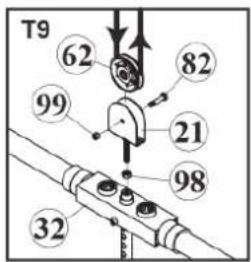
- Assemble the pulley block (21) to the two way top plate (32) with one nut (98) by screwing it at least 1/3 into the selector rod (29) [T9].
- Assemble one pulley (62) to the pulley block (21) with one bolt (82) and one nut (99) and route the cable (71) underneath the pulley [T9].
- Assemble one pulley (62) to the rear top frame (11) with one bolt (82) and one nut (99) and route the cable (71) over the pulley [T10].
- Assemble two pulleys (62) to the right top frame (16R) with one bolt (82) and one nut (99) each and route the cable (71) over the pulleys [T11 & T12].
- Assemble one pulley (62) between two double cable retainer plates (22) with one bolt (82) and one nut (99) and route the cable (71) underneath the pulley [T13].
- Assemble two pulleys (62) to the right top frame (16R) with one bolt (82) and one nut (99) each and route the cable (71) over the pulleys [T14 & T15].
- Assemble two pulleys (62) to the pulley holder of the right pulley height adjuster (10R) with two bolts (82) and two nuts (99), route the cable (71) downwards and pull it out between the two pulleys [T16 & T17].
NOTICE
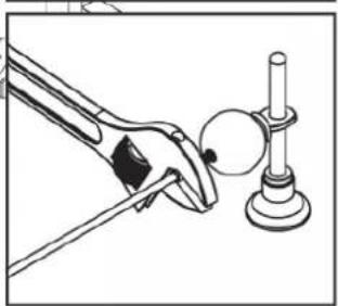
To make the assembly of the cable head easier: it is recommended to use a pliers to keep the cable in place and attach the cable head to the selector rod to keep it in place.
- Attach the head of the cable (74) to the bolt end of the pulley column cable (71).

Ball End
Pulley Column Cable (71)
Bolt End
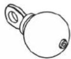
Head of Cable (74)




natural_image
Illustration of a hand using a tool to lift a sphere around a stand (no text or symbols)
Step 8: Assembly of the Top Cable
i NOTICE
Assemble the pulleys and cables simultaneously.
- Assemble one pulley (62) to the pulley bracket of the connector top frame (13) with one bolt (82) and one nut (99) [A1].
- Insert the bolt end of the cable (72) into the connector top frame (13) and pull it through [A1].
- Assemble one pulley (62) to the connector top frame (13) with one bolt (82) and one nut (99) and route the cable (72) around the pulley [A2].
- Assemble one pulley (62) to the rear top frame (11) with one bolt (82) and one nut (99) and route the cable (72) over the pulley [A3].
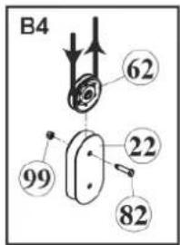
- Assemble one pulley (62) between two double cable retainer plates (22) with one bolt (82) and one nut (99) and route the cable (72) underneath the pulley [A4].
- Guide the cable (72) upwards and screw the bolt end of the top cable into the left top frame (15L) [A5].
- Repeat these steps for the right side [B1-B5].
Top Cable (72)



Step 9: Assembly of the Low Cable
i NOTICE
Assemble the pulleys and cables simultaneously.
- Screw the threaded bolt end of the low cable (73) into the right pulley height adjuster (10R) [L1].
- Assemble two pulleys (62) to the right base frame (3R) with one bolt (82) and one nut (99) each and route the cable (73) underneath the pulley [L2 & L3].
- Assemble one pulley (62) between two double cable retainer plates (22) with one bolt (82) and one nut (99) and route the cable (73) over the pulley [L4].
- Assemble one pulley (62) to the right base frame (3R) with one bolt (82) and one nut (99) and route the cable (73) underneath the pulley [L5].
- Assemble one pulley (62) between two double cable retainer plates (22) with one bolt (82) and one nut (99) and route the cable (73) over the pulley [L6].
- Assemble one pulley (62) to the base frame (1) with one bolt (82) and one nut (99) and route the cable (73) underneath the pulley [L7].
- Assemble one pulley (62) to the pulley bracket of the base frame (1) with one knob (47) and one nut (116) and route the cable (73) around the pulley and pull it out [L8].
i NOTICE
To make the assembly of the cable head easier: it is recommended to use a pliers to keep the cable in place and attach the cable head to the selector rod to keep it in place.
-
Attach the head of the cable (74) to the bolt end of the cable (73).
-
Repeat these steps for the left side.
Head of Cable (74)


natural_image
Illustration of a pliers applying force to a circular object on a stand (no text or symbols)Step 10: Assembly of the Top Panel & Stack Guard
- Assemble the top panel (14) to the rear top frame (11) with four bolts (88) and four plastic studs (51).
- Assemble the stack guard (17) to the base frame (1) with four bolts (84) and four washers (96).

Step 11: Assembly of the Olympic Adapter Sleeve
- Assemble eight lever support rods (28), eight rubber cushions (45) and eight adapter sleeves (63) to each side of the rear upright frame (5) with six weight holder brackets (25), eight washers (95) and eight bolts (83).
- Assemble one bracket (24) to each side of the rear upright frame (5) with four bolts (81), eight washers (95) and four nuts (99).

Step 12: Assembly of the Accessories
- Remove the slack in the cables by adjusting the cable bolts on the left and right pulley height adjusters (9L & 10R) and the pulley block (21) located on the top plates of the stack.
i NOTICE
The cable bolts and pulley block (21) should not be able to rotate when tightened.
- Tighten all Jam-Nuts.
- Attach the lat bar (30) with two snap hooks (69) on the top cable (72).
- Attach the curl bar (31) with one snap hook (69) on the low cable (73).
- Attach two multiple D-ring single handles (67) with two snap hooks (69) on the pulley column cable (71).
- Make sure that all cables are properly seated in all of the pulleys.
- Tighten all bolts and nuts.

3.1 General Instructions

WARNING
- The storage location should be chosen so that improper use by third parties or children can be prevented.
- If your equipment does not have transportation wheels, the equipment must be disassembled before transportation.

ATTENTION
+ Make sure that the equipment is protected from moisture, dust and dirt in the selected storage location. The storage location should be dry and well ventilated and have a constant ambient temperature between 10^ C and 35^ C.
4.1 General Instructions

WARNING
+ Do not make any improper changes to the equipment.

CAUTION
+ Damaged or worn components may affect your safety and the life of the equipment. Therefore, immediately replace damaged or worn components. In such a case, contact the contract partner. The equipment must not be used until it has been repaired. If necessary, use only original spare parts.

ATTENTION
+ In addition to the instructions and recommendations for maintenance and care given here, additional service and/or repair work may be necessary; this must only be carried out by authorised service technicians.
4.2 Faults and Fault Diagnosis
The equipment undergoes regular quality controls during production. Nevertheless, faults or malfunctions may occur. Frequently, individual parts are responsible for these disturbances, an exchange is usually sufficient. Please refer to the following overview for the most common errors and how to correct them. If the equipment still does not function properly, contact your contract partner.
| Fault | Cause | Solution |
| Grinding noises | Cables or pulleys do not run smoothly or are damaged | + Visual inspection of the cable routing or the pulley guide+ If damaged, replace the defective part |
| Weight hanging in the air | Cable tensioned too tight | Readjust cable tension |
| Cable without tension | Cable too loose | + Check cable routing+ Readjust cable tension |
| Squeaking & cracking noises | Screw connections loosened or too tight | + Check or lubricate screw connections*+ Check cable routing |
| Unit wobbles | + Uneven ground+ Loose screw connections | + Align unit+ Tighten screw connections |
| Heavy draught | + Weight holders/guide rods too dry+ Faulty cable routing | + Lubricate guide rods*+ Check cable routing |
* With a grease-free silicone oil or silicone spray.
4.3 Maintenance and Inspection Calendar
To avoid damage from body sweat, the equipment must be cleaned with a damp towel (no solvents!) after each training session.
The following routine tasks must be performed at the specified intervals:
| Part Weekly Monthly Quarterly | |||
| Cables C I | |||
| Screw connections I | |||
| Pulleys and cable routing I | |||
| Slide rails/Guide rods I | |||
| Legend: C = clean; I = inspect | |||
5 DISPOSAL
At the end of its operational life, this equipment cannot be disposed of in normal household waste. Instead, it must be disposed of via an recycling centre. Further information can be obtained from your local authority's recycling service.

The materials can be recycled as per their symbols. Through the reuse, recycling of materials or other forms of recovery of old equipment, you make an important contribution to the protection of the environment.
6 RECOMMENDEDACCESSORIES
To make your training experience even more efficient and pleasant, we recommend that you add suiting accessories to your fitness equipment. For training equipment like smith machines, weight benches or racks this could for example be a floor mat, which makes your fitness equipment stand more securely and also protects the floor from sweat but it could be also additional weights, handles, foot straps for leg exercises or triceps ropes. For some smith machines, there are also optional add-ons such as leg presses that make your workout even more intense and comprehensive.
Our range of accessories offers the highest quality and makes training even better. If you would like to find out more about compatible accessories, please go to the detail page of the product in our webshop (the easiest way is to enter the article number in the search field above) and go to the recommended accessories on this page. Of course, you can also contact our customer service: by telephone, e-mail, in one of our branches or via our social media channels. We will be happy to advise you!


natural_image
Black sport-Tledge athletic strap device with label 'chest strap' (no other text or symbols visible)
natural_image
Stack of black rectangular electronic components with rounded corners (no visible text or symbols)
natural_image
Close-up of a black and white mechanical clamp or spring with two spherical ends (no text or symbols visible)triceps rope
weight block extension
7.1 Serial Number and Model Name
In order to provide you with the best possible service, please have the model name, article number, serial number, exploded drawing and parts list ready. The corresponding contact options can be found in chapter 10 of this operating manual.
i NOTICE
The serial number of your equipment is unique. It's located on a white sticker. The exact position of this sticker is shown in the following illustration.
Enter the serial number in the appropriate fi eld.

natural_image
Technical line drawing of a mechanical lifting frame assembly with no visible text or symbolsSerial number:
Brand / Category:
Bodycraft / multi gym
Model Name:
Super Gym 1
Article Number:
BC-SG1
7.2 Parts List
| No. | Name | Qty. |
| 1 BASE | FRAME 1 | |
| 2L LEFT | BASE FRAME 1 | |
| 3R RIGHT | BASE FRAME 1 | |
| 4 FRONT | UPRIGHT FRAME 2 | |
| 5 REAR | UPRIGHT FRAME 2 | |
| 6 GUIDE | ROD 2 | |
| 7L LEFT | SAFETY ARM 1 | |
| 8R RIGHT | SAFETY ARM 1 | |
| 9L LEFT | PULLEY HEIGHT ADJUSTER 1 | |
| 10R RIGHT | PULLEY HEIGHT ADJUSTER 1 | |
| 11 REAR | TOP FRAME | 1 |
| 12 CHIN | UP FRAME | 1 |
| 13 CONNECTOR | TOP FRAME | 1 |
| 14 TOP | PANEL | 1 |
| 15L | LEFT TOP FRAME | 1 |
| 16R RIGHT | TOP FRAME | 1 |
| 17 STACK | GUARDS | 1 |
| 18 TOP | FRAME PULLEY BRACKET | 2 |
| 19 LOW | CABLE PULLEY BRACKET | 2 |
| 20 | ROTATING PULLEY HOLDER | 2 |
| 21 PULLEY | BLOCK | 1 |
| 22 DOUBLE | CABLE RETAINER PLATE | 8 |
| 23 LAT | BAR BRACKET | 2 |
| 24 BRACKET | 2 | |
| 25 WEIGHT | HOLDER BRACKET | 6 |
| 26 HOOK | PLATE 2 | |
| 27 AXLE | COLLAR | 4 |
| 28 LEVER | SUPPORT ROD | 8 |
| 29 SELECTOR | ROD | 1 |
| 30 LAT | BAR | 1 |
| 31 CURL | BAR | 1 |
| 32 | TWO WAY TOP PLATE | 1 |
| 33 TOP | GUIDE ROD HOLDER 1 | |
| 34 STACK | SPACER 2 | |
| 35 10 LB. WEIGHT PLATE 19 | ||
| 36 75W | X 45H END CAP 4 | |
| 37 45 X | 75mm PLUG 3 | |
| 38 25 X | 75mm PLUG 2 | |
| 39 45mm | SQ. PLUG 2 | |
| 40 HOLLOW PLUG 8 | ||
| 41 1" BUSHING FOR TWO WAY TOP PLATE 2 | ||
| 42 1" BUSHING 4 | ||
| 43 1/2" ID | BUSHING 8 | |
| 44 PLASTIC GUIDE ROD HOLDER 2 | ||
| 45 RUBBER CUSHION | 14 | |
| 46 RUBBER DONUT | 1 | |
| 47 3/8" X 1-1/2L KNOB | 2 | |
| 48 2" OLYMPIC SPRING | 2 | |
| 49 STEEL PLATE | 2 | |
| 50 BUMPER | 2 | |
| 51 PLASTIC STUDS | 4 | |
| 52 ALU MINUM WASHER | 2 | |
| 53 1" ID SEAL RINGLET | 4 | |
| 54 SPRING CLIP | 4 | |
| 55 STOPPER | 4 | |
| 56 PIN BOLT | 4 | |
| 57 SPRING | 4 | |
| 58 MAGNET | 2 | |
| 59 SELECTOR PIN | 1 | |
| 60 ROUND PLUG | 10 | |
| 61 1" T SHAPE END PLUG | 2 | |
| 62 PULLEY | 39 | |
| 63 OLYMPIC ADAPTER SLEEVE | 10 | |
| 64 1" X | 200mm ROUND HAND GRIP | 2 |
| 65 1-1/4" HAND GRIP | 2 | |
| 66 1-1/4" X | 135mm ROUND HAND GRIP | 2 |
| 67 MULTIPLE D-RING SINGLE HANDLE | 2 | |
| 68 ANKLE STRAP 1 | ||
| 69 SNAP HOOK 8 | ||
| 70 CHAIN 2 | ||
| 71 PULLEY COLUMN CABLE 1 | ||
| 72 TOP CABLE 2 | ||
| 73 LOW CABLE 2 | ||
| 74 HEAD OF CABLE 3 | ||
| 75 1/2" X 6" HEX BOLT 2 | ||
| 76 1/2" X 4-1/4" HEX BOLT 10 | ||
| 77 PLASTIC COVER 2 | ||
| 78 1/2" X 3" HEX BOLT 8 | ||
| 79 1/2" X 2-3/4" HEX BOLT 6 | ||
| 80 1/2" X 1" HEX THREADED BOLT 9 | ||
| 81 3/8" X 2-1/2" HEX BOLT 4 | ||
| 82 3/8" X 1-3/4" HEX BOLT 37 | ||
| 83 3/8" X 1" HEX THREADED BOLT 8 | ||
| 84 5/16" X 1/2" HEX THREADED BOLT 4 | ||
| 85 TOP PLATE BOLT 1 | ||
| 86 3/8" X 1" HEX SOCKEN DOME BOLT 1 | ||
| 87 5/16" X 5/8" HEX SOCKEN DOME BOLT 2 | ||
| 88 M6 X 40L HEX SOCKEN DOME BOLT 4 | ||
| 89 5/16" X 1-1/4" SCREW 3 | ||
| 90 M5 SCREW 2 | ||
| 91 M5 TAPPING SCREW 10 | ||
| 92 5/16" X 3/8" INNER HEX SCREW 10 | ||
| 93 5/16" X 1/4" INNER HEX SCREW 2 | ||
| 94 1/2" WASHER 51 | ||
| 95 3/8" WASHER 16 | ||
| 96 5/16" WASHER 4 | ||
| 97 1/2" NYLON NUT 16 | ||
| 98 1/2" NUT 1 | ||
| 99 3/8" THICKER NYLON NUT 41 | ||
| 100 M5 NYLON NUT 2 | ||
| 101 5/16" LARGER NUT 2 | ||
| 102 TRICEP ROPE 1 | ||
| 103 CHIN ASSIST STRAP | 1 | |
| 104 SPORT BAR | 1 | |
| 105 LONG BAR | 1 | |
| 106 1" X 295L FOAM GRIP | 1 | |
| 107 1" X 900L FOAM GRIP | 1 | |
| 108 SPORT BAR COLLAR | 3 | |
| 109 SPACER | 1 | |
| 110 BEARING | 6 | |
| 111 C - RING | 3 | |
| 112 5/16" SMALLER NUT | 1 | |
| 113 NON SLIP | 2 | |
| 114 1-1/4" ROUNG PLUG | 2 | |
| 115 BUTTON CAP | 4 | |
| 116 3/8" THINER NYLON NUT | 2 | |
| 117 M6 X 6mm INNER HEX SCREW | 4 | |
7.3 Exploded Drawing

Training equipment from Bodycraft ^® is subject to strict quality control. However, if a fitness equipment purchased from us does not work perfectly, we take it very seriously and ask you to contact our customer service as indicated. We are happy to help you by phone via our service hotline.
Error Descriptions
Your fitness equipment is developed for long-term, high-quality training. However, should a problem arise, please first read the operating instructions. For further assistance, please contact your contract partner or call our service hotline. To ensure your problem is solved as quickly as possible, please describe the defect as exactly as possible.
In addition to the statutory warranty, we provide a warranty for every fitness equipment purchased from us according to the following provisions.
Your statutory rights are not aff ected.
Warrantee
The warrantee is the first/original buyer and/or any person who received a newly purchased product as a gift from the original buyer.
Warranty period
The warranty periods, shown on our web shop, begin on delivery of the fitness equipment. The respective warranty periods for your equipment can be found on its product website.
Repair Costs
According to our choice, there will either be a repair, a replacement of individual damaged parts or a complete replacement. Spare parts, that have to be mounted while assembling the equipment, have to be replaced by the warrantee personally and are not a part of repair. After the expiration of the warranty period, the responsibility for parts costs, repair costs, installation costs and delivery costs lies with the warranty holder.
The terms of use are defined as follows:
- Home use: solely for private use in private households up to 3 hours per day
- Semi-professional use: up to 6 hours per day (e. g. rehabilitation centres, hotels, clubs, company gyms)
- Professional use: more than 6 hours per day (e.g. commercial gyms)
Warranty Service
Within the warranty period, equipment which develops faults as a result of material or manufacturing defects, will be repaired or replaced at our discretion. Ownership of equipment or parts of equipment which have been replaced is transferred to us. The warranty period is not extended nor does a new warranty period begin following repair or replacement under the warranty.
Warranty Conditions
For the warranty to be valid, the following steps must be taken:
Please contact our customer service by email or phone. If the product under warranty has to be sent in for repair, the seller bears costs. After expiry of the warranty, the buyer bears the costs of transport and insurance. If the fault is covered by our warranty, you will receive a new or repaired equipment in return.
Warranty claims are invalid in case of damage resulting from:
- misuse or improper handling
- environmental influences (moisture, heat, electrical surge, dust, etc.)
- failure to follow the current safety measures for the equipment
- failure to follow the operating instructions
- use of force (e. g. hitting, kicking, falling)
- interventions which were not carried out by one of our authorized service centres
- unauthorised repair attempts
Proof of Purchase and Serial Number
Please make sure that you are able to provide the appropriate receipt when claiming on your warranty. So that we can clearly identify the model of your equipment, and for the purposes of our quality control, you will need to give the serial number of your equipment, when contacting the service team. Where possible please have your serial number and your customer number ready when you call our service hotline. It will help us to deal with your request swiftly.
If you cannot find the serial number on your fitness equipment, our service team is at your disposal to offer further information.
Service outside of the Warranty Period
We are also happy to issue an individual cost estimate if there is a problem with your fitness equipment after the warranty has expired, or in cases which do not fall under the terms of the warranty, e. g. normal wear and tear. Please contact our customer service team to find a quick and cost-effective solution to your problem. In such a case you will be responsible for the delivery costs.
Communication
Many problems can be solved just by speaking to us as your specialist supplier. We know how important it is to you as a user of the fitness equipment to have problems solved quickly and simply, so you can enjoy working out with minimal interruption. For that reason, we also want to resolve your queries quickly and in a straightforward manner. Thus, please always keep your customer number and the serial number of the faulty equipment handy.
DE DK FR
| TECHNIK TEKNIK OG SERVICE TECHNIQUE & SERVICE | ||
| 80 90 16 50+49 4621 4210-945info@fi tshop.dk | +33 (0) 189 530984+49 4621 42 10 933info@fi tshop.frVous trouverez les heures d'ouverture sur notre site Internet. | |
| SERVICE0800 20 20277(kostenlos)04621 4210 - 0info@sport-tiedje.deÖffnungszeiten entnehmen Sie unserer Homepage. | PL | BE |
| DZIAŁ TECHNICZNY I SERWIS22 307 43 21+49 4621 42 10-948info@fi tshop.plGodziny otwarcia można znaleźć na stronie głównej. | TECHNIQUE & SERVICE02 732 46 77+49 4621 4210 933info@fi tshop.beVous trouverez les heures d'ouverture sur notre site Internet. | |
| UK | NL | INT |
| CUSTOMER SUPPORT00800 2020 2772+494621 4210 944info@sport-tiedje.co.ukYou can find the opening hours on our homepage. | TECHNISCHE DIENST & SERVICE+31 172 619961service@fitshop.nlDe openingstijden vindt u op onze homepage. | TECHNICAL SUPPORT & SERVICE+49 4621 4210-944service-int@sport-tiedje.deYou can find the opening hours on our homepage. |
Please find a detailed overview including address and opening hours for all stores of the Sport-Tiedje Group in Germany and abroad on the following website:
www.sport-tiedje.com/en/stores
WE LIVE FITNESS
WEBSHOP AND SOCIAL MEDIA
Sport-Tiedje is Europe's largest specialist store for home fitness equipment with currently over 70 stores and one of the world's most renowned online mail order companies for fitness equipment. Private customers order via the 25 web shops in the respective national language or have their desired equipment assembled on site. In addition, the company supplies fitness studios, hotels, sports clubs, companies and physio practices with professional equipment for endurance and strength training.
Sport-Tiedje offers a wide range of fitness equipment from renowned manufacturers, high-quality in-house developments and comprehensive services, such as a build-up service and sports scientific advice before and after the purchase. The company employs numerous sports scientists, fitness trainers and competitive athletes.
Visit us also on our social media platforms or our blog!

www.sport-tiedje.co.uk www.sport-tiedje.de/blog

www.facebook.com/SportTiedje

www.instagram.com/sporttiedje

www.youtube.com/user/sporttiedje
TAURUS
cardiostrong
BODYCRAFT
cardiojump
DUKEFITNESS
DARWIN
Notes
Notes
BODYCRAFT
- Content
- GENERAL INFORMATION 7
- ASSEMBLY 10
- STORAGE AND TRANSPORT 31
- General Instructions 31
- TROUBLESHOOTING, CARE AND MAINTENANCE 32
- DISPOSAL 33
- RECOMMENDED ACCESSORIES 34
- ORDERING SPARE PARTS 35
- WARRANTY 41
- CONTACT 43
- Dear customer,
- Intended Use
- Disclaimer
- BODYCRAFT
- ABOUT THIS MANUAL
- ATTENTION
- CAUTION
- WARNING
- DANGER
- i NOTICE
- Technical Data
- Weight and Dimensions
- Weight block (67.5 kg)
- Weight block (90 kg)
- Personal Safety
- Set-UpPlace
- GeneralInstructions
- Scope of Delivery
- DESCRIPTION QTY.
- Assembly
- Step 1: Assembly of the Base Frame
- Step 2: Assembly of the Upright Frame
- Step 3: Assembly of the Top Frame
- Step 4: Assembly of the Rear Top Frame & Chin Up Frame
- Step 5: Assembly of the Connector Top Frame
- Step 6: Assembly of the Guide Rods and Weight Plates
- lbs Stack
- lbs Stack
- NOTICE
- Pulley Column Cable (71)
- Step 8: Assembly of the Top Cable
- Top Cable (72)
- Step 9: Assembly of the Low Cable
- Head of Cable (74)
- Step 10: Assembly of the Top Panel & Stack Guard
- Step 11: Assembly of the Olympic Adapter Sleeve
- Step 12: Assembly of the Accessories
- General Instructions
- General Instructions
- Faults and Fault Diagnosis
- Maintenance and Inspection Calendar
- DISPOSAL
- RECOMMENDEDACCESSORIES
- Serial Number and Model Name
- Serial number:
- Brand / Category:
- Model Name:
- Article Number:
- Exploded Drawing
- Error Descriptions
- Warrantee
- Warranty period
- Repair Costs
- The terms of use are defined as follows:
- Warranty Service
- Warranty Conditions
- Warranty claims are invalid in case of damage resulting from:
- Proof of Purchase and Serial Number
- Service outside of the Warranty Period
- Communication
- WE LIVE FITNESS
- WEBSHOP AND SOCIAL MEDIA
Brand : BodyCraft
Model : Super Gym 1
Category : Fitness Equipment