
31.2000 - Sound Level Meter TFA - Free user manual and instructions
Find the device manual for free 31.2000 TFA in PDF.


| Product Type | Sound Level Meter |
| Brand | TFA |
| Model | 31.2000 |
| Standard | IEC651 Type2, ANSI S1.4 Type2 |
| Frequency Range | 31.5 Hz to 8 kHz |
| Measuring Level Range | 30 to 130 dB |
| Frequency Weighting | A and C |
| Microphone | 1/2 inch electret condenser microphone |
| Display | LCD with 4-digit digital and 50-segment bargraph |
| Resolution | 0.1 dB (digital), 1 dB (bargraph) |
| Display Update | 0.5 sec (digital), 50 ms (bargraph) |
| Time Weighting | FAST (125 ms), SLOW (1 sec) |
| Level Ranges | Lo: 30-80 dB, Med: 50-100 dB, Hi: 80-130 dB, Auto: 30-130 dB |
| Accuracy | ±1.5 dB (reference conditions @ 94 dB, 1 kHz) |
| Dynamic Range | 100 dB |
| Alarm Indication | OVER (input above upper limit), UNDER (input below lower limit) |
| MAX/MIN Hold | Yes |
| AC Output | 1 Vrms at full scale, impedance approx. 100 Ω |
| DC Output | 10 mV/dB, impedance approx. 1 kΩ |
| Power Supply | 9V battery (006P, IEC 6F22, NEDA 1604) or AC adapter 9 VDC |
| Battery Life | Approx. 50 hours with alkaline battery |
| Data Logger Capacity | Up to 32,000 records |
| Interface | RS-232, 9600 bps, N, 8, 1 |
| Dimensions (L × W × H) | 275 × 64 × 30 mm |
| Weight | 285 g (including battery) |
| Operating Temperature | 0 to 40 °C |
| Operating Humidity | 10 to 90% RH |
| Storage Temperature | -10 to 60 °C |
| Storage Humidity | 10 to 75% RH |
| Altitude | Up to 2000 meters |
| Accessories | 9V battery, carrying case, screwdriver, manual, windscreen, 3.5 mm plug, software, RS-232 cable |
| Maintenance | Wipe with dry cloth; do not use abrasives or solvents |
| Safety | CE compliant |
| Calibration | Recommended annually using acoustic calibrator (94 dB, 1 kHz) |
Frequently Asked Questions - 31.2000 TFA
User questions about 31.2000 TFA
0 question about this device. Answer the ones you know or ask your own.
Ask a new question about this device
Download the instructions for your Sound Level Meter in PDF format for free! Find your manual 31.2000 - TFA and take your electronic device back in hand. On this page are published all the documents necessary for the use of your device. 31.2000 by TFA.
USER MANUAL 31.2000 TFA
IV. NAME AND FUNCTIONS

(1) Windschutz
![graph TD A["SET"] --> B["0001 int"]](/content/2026/05/789296/images/66fce66b82daf58b43ff1b7efede96f58520e7886fde66ed613ba9d31842a153.jpg)
Schaltflächen

Environment conditions 17
Maintenance & Clearing 17
Safety symbols 17
II. GENERAL DESCRIPTION 17
III. SPECIFICATIONS 18
IV. NAME AND FUNCTIONS 19
V. CLOCK & INTV SETUP 22
DataLogger 22
Clock Setup 22
Recording Interval Setup 23
Auto Power Off 23
VI. CALIBRATION PROCEDURES 23
VII. MEASUREMENT PREPARATION 24
VIII. OPERATING PRECAUTIONS 24
IX. MEASUREMENT 25
X. Setup TestLink SE-322 (Sound Level Meter) - RS232 interface software 25
I. SAFETY INFORMATION
Read the following safety information carefully before attempting to operate or service the meter.
Use the meter only as specified in this manual; otherwise, the protection provided by the meter may be impaired.
Environment conditions
β Altitude up to 2000 meters
β Relatively humidity 90% max.
β Operation Ambient 0 \~ 40;C
Maintenance & Clearing
β Repairs or servicing not covered in this manual should only be performed by qualified personnel.
β Periodically wipe the case with a dry cloth. Do not use abrasives or solvents on this instruments.
Safety symbols
CE Comply with EMC
When servicing, use only specified replacement parts.
II. GENERAL DESCRIPTION
Thank you for using our Data Logger Sound Level Meter. To ensure that you can get the most from it, we recommend that you read and follow the manual carefully before use.
This unit conforms to the IEC651 type2, ANSI S1.4 Type2 for Sound Level Meters.
This Data Logger Sound Level Meter internal memory can keep up to 32000 records.(Note 1.)
It uses RS232 interface to perform bi-directional communication with PC.
Note1:
Every time you press “REC” button to start recording data and press “REC” button again to stop recording, there will be a data set in memory, you can store as many data sets as you want unit memory is full.
III. SPECIFICATIONS
Standard applied: IEC651 Type2, ANSI S1.4 Type2.
Frequency range: 31.5Hz \~ 8KHz
Measuring level range: 30 \~ 130dB
Frequency weighting: A / C
Microphone: 1/2 inch electret condenser microphone
Display: LCD
Digital display: 4 digits
Resolution: 0.1dB
Display Update: 0.5 sec.
Analog display: 50 segment bargraph
Resolution: 1dB
Display Update: 50 mS
Time weighting: FAST (125 ms), SLOW (1 sec.)
Level ranges:
Lo: 30 - 80 dB
Med: 50 – 100 dB
Hi: 80 - 130 dB
Auto: 30 - 130 dB
Accuracy: ±1.5dB (under reference conditions @ 94dB, 1KHz)
Dynamic range: 100 dB
Alarm function: "OVER" is when input is more than upper limit of range.
"UNDER" is when input is Less than lower limit of range.
MAX/MIN hold: Hold readings the Maximum and Minimum Value.
AC output: 1 Vrms at FS (full scale).
Output impedance: Approx. 100Ω
FS: means the upper limit of each level range.
DC output: 10mV / dB, output impedance approx. 1KΩ
Power supply: One 9V battery, 006P or IEC 6F22 or NEDA 1604.
Power life: About 50hrs ( alkaline battery )
AC adapter: Voltage 9 VDC (8-15VDC Max)
Supply current : > 30mADC
Socket: pin → Ground
Casing → Positive
External Diameter → 3.5mm
Internal Diameter → 1.35mm
Electromagnetic Compatibility:
RF field = 3V/m
Total accuracy = specified accuracy + 0.5dB
Operation temperature: 0 to 40°C (32 to 104°C)
Operation humidity: 10 to 90%RH
Storage temperature: -10 to 60°C (14 to 140°C)
Storage humidity: 10 to 75%RH
Dimensions: 275 (L) ×64 (W) ×30 (H)mm
10.8 (L) ×2.5 (W) ×1.2 (H)inch
Weight: 285g (including battery)
Accessories: 9V battery, carrying case, Screwdriver,
Instruction manual. Windscreen, 3.5ψ plug,
software, RS-232 cable.
IV. NAME AND FUNCTIONS

(1) Windscreen
If you operate at wind speed over 10m/sec, please put protective accessories in front of the microphone.
(2) Display
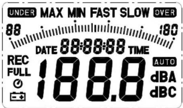
SYMBOL
FUNCTION
LCD
4 digits
MAX
Maximum indication
MIN
Minimum indication
OVER
Over range
UNDER
Under range
FAST
Fast response
SLOW
Slow response
dBA
A-Weighting
dBC
C-Weighting
88-180
Range Indicate
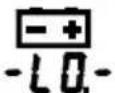
Low-Battery
AUTO
Under range 20dB
REC
Auto Level range selective
FULL
Recording Datalogger

Memory full
Auto Power OFF active
(3) Power & Backlight button
The (1) key turns the sound level meter ON or OFF and backlight ON & OFF.
Press it once to turn on the sound level meter.
Press it again for moment to turn ON or OFF backlight.
Press and hold this button 3 second to turn OFF the power.
Note: When the user power it on, the LCD will show how much memory space is available to use.
(4) MAX / MIN hold button
Press 📄 button to enter the maximum and minimum recording mode. Select the proper Level range before using MAX/MIN to ensure that reading value will not exceed the measurement range. Press once to select MAX value. Press again to select MIN value, and press again to select current value with “MAX MIN” annunciator blinking.
Press MAX and hold down button for 2 seconds to exit the MAX MIN mode.
Note: If change sound level range or change A-C weight, the MAX.MIN mode will clear.
REC
(5) Record Datalogger button
When one press the button, the meter will star recording. The "REC" annunciator are display, press again will stop recording.
(6) Frequency Weighting select button
A : A - Weighting. for general sound level measurements.
C : C - Weighting. for checking the low-frequency content of noise.
( If the C-Weighted level is much higher than the A-weighted level, then there is a large amount of low-frequency noise )
(7) Time weighting select button
FAST : for normal measurements
SLOW : for checking average level of fluctuating noise.
(8) Level range control button
Each time you press LEVEL button, the level range will change between "Lo" level, "Med" level, "Hi" level and "Auto" level in the circular.
(9) Microphone
1/2 inch Electret Condenser microphone
(10) CAL potentiometer
Calibration control, For level calibration adjustment.
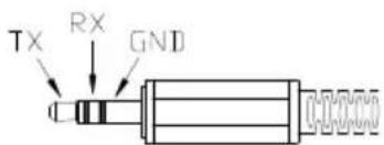
(11) RS-232 Interface:
The RS-232 signal output is a 9600 bps N, 8, 1 serial interface.
(12) Signal output terminal
AC: 1 Vrms Corresponding to each range step.
Output impedance 100Ω
Output signal by standard 3.5mm coaxial socket signal on pin.
Note: At "Auto" level range, output signal is Auto select on "Lo" or
"Med" or "Hi" level range.
DC: Output: 10mV/dB
Output impedance 1KΩ
Output signal by standard 3.5mm coaxial socket signal on middle.

(13) External DC 9V power supply terminal
For connection with AC adapter.
(14) Tripod mounting screw.
(15) Battery Cover
V. DATA LOGGER CLOCK & INTERVAL SETUP
β DataLogger:
When one presses the "REC" button, the meter will start recording, and pressing the "REC" button again will stop recording. If you want to clear the memory, power off the meter, then press and hold "REC" button and then press power button and hold at least 5 seconds, then LCD will show "CLR" and "SURE" to clear the memory.

β Clock Setup :

1: press and hold "A/C" button and then power on the meter:
2: press "MAX MIN"(clock) button:
3: press "REC" ▲ or "LEVEL" ▼ to increase or decrease number, press "MAX MIN"(clock) to adjust next item. The adjusting order is year → month → day → hour → minute, then press "MAX MIN" (clock) to finish adjusting. If you want abort during a setup process, press power button to cancel.
β Recording Interval Setup :
![graph TD A["SET"] --> B["0001 int"]](/content/2026/05/789296/images/06e7035e0195b16ecfc3736c83715bfc5416c2361609d1cfa6603443a21b3c63.jpg)
1: press and hold "A/C" button and then power on the meter:
2: press "FAST/SLOW"(INTV) button:
3: press "REC" ▲ or "LEVEL" ▼ to increase or decrease number, press "FAST/SLOW" (INTV) to adjust next item, then press "FAST/SLOW" (INTV) to finish. If you want abort during a setup process, press power button to cancel.
β Auto Power Off:
By default, when the meter is powered on, it is under auto power off mode. The meter will power itself off after 30 minutes if no key operation and no RS232 communication and no recording combination at power on can disable auto power off.
One may press and hold "FAST/SLOW" button and then power on the meter and the ⏻ will not show up to indicate that auto power off is disabled.
VI. CALIBRATION PROCEDURES

(1) Make the following switch settings.
Display : dBA
Time weighting : FAST
Measurement mode : MAX MIN Mode function disable.
Level range : 50 to 100dB
(2) Insert the microphone housing carefully into the insertion hole of the calibrator.
(3) Turn on the switch of calibrator and adjust the CAL potentiometer of the unit. The level display will indicate the desired level.
All products are well calibrated before shipment.
Recommended Recalibration cycle: 1 year.
VII. MEASUREMENT PREPARATION
(1) Battery Loading
Remove the battery cover on the back and put in one 9V Battery.
(2) Battery Replacement
When the battery voltage drops below the operating voltage, this symbol will appear 📄 Replace 9 Volt battery.
(3) AC Adapter Connection
When the AC adapter is used, insert the plugs of the adapter into the DC9V connector on the side panel.
VIII. OPERATING PRECAUTIONS
(1) Wind blowing across the microphone would bring additional extraneous noise. When using the instrument in the presence of wind, it is a must to mount the windscreen to not pick up undesirable signals.
(2) Calibrate the instrument before operation if the instrument was not in use for a long time or operated in bad environment.
(3) Do not store or operate the instrument at high temperature and high humidity environment.
(4) Keep microphone dry and avoid severe vibration.
(5) Please take out the battery and keep the instrument in low humidity environment. When not in use.
IX. MEASUREMENT
(1) Open battery cover and install a 9V battery in the battery compartment.
(2) Turn power on and select the desired response Time and Weighting. If the sound source consists of short bursts or only catching sound peak, set response to FAST. To measure average sound level, use the SLOW setting.
Select A-weighting for general noise sound level and C-weighting for measuring sound level of acoustic material.
(3) Select desired Level.
(4) Hold the instrument comfortably in hand or fix on tripod and point the microphone at the suspected noise source, the sound pressure level will be displayed.
(5) When MAX MIN (maximum, minimum hold) mode is chosen. The instrument captures and holds the maximum and minimum noise level for a long period using any of the time weightings and ranges. Press the MAX MIN button 2 seconds to clear the MAX/MIN reading . “MAX/MIN” symbol disappears.
(6) Turn OFF the instrument and remove battery when not in use.
X. Setup TestLink SE-322 (Sound Level Meter)—RS232 interface software:
ü The TestLink package contains:
1.80mm CD.
- Custom designed RS232 cable for TestLink.
ü System Required:
Windows 95 or Windows 98 or Windows NT 4.0 above.
ü Minimum Hardware Required:
PC or Notebook with Pentium 90MHz or higher, 32 MB RAM ;
At least 5 MB byte hard disk space available to install TestLink.
Recommended resolution 800X600.
β Install TestLink:
- We recommend close all other application before installing TestLink
- Insert setup CD disk to CD disk drive.
- Choose the Start button on the Taskbar and select Run.
- Type E:\SETUP and choose OK, then it will copy SE322.exe (executable file) and help file to your hard disk (default is c:\program files\TestLink\SE322).
For detailed other operation instruction, please refer to the online help while executing SE322.
β Main Menu
File | Open - Retrieve files from the disk.
Save - Save the active window (when the caption bar is highlighted) data to the disk.
Print - Print the data of the active window (graph or list).
Printer Setup - Select printer.
File | Exit: Terminates TestLink program.
View | Control Panel: By opening the Panel Window, the user can control meter via the button in this window.
View | Real-Time Graph: Open Real-Time Graph display to graph the present data.
Real Time Data | Run - Start collecting real time data.
Stop - Stop collecting real time data.
DataLogger: By opening the DataLogger Window, the user can load recorded data of meter to PC in this window.
Output To Graph - Graphing tabular data . interface. For better result, the user may close the panel window .
Graph

Tool Bar
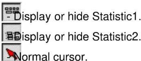

- When selected, the mouse cursor will become a cross sign when moving to the graph, click on the graph to mark a cross sign on the graph.

- When selected, the mouse cursor will become a "I" sign when moving to the graph, click on the graph to annotate.

Color graph.

Monochrome graph.
You can choose a rectangle area on the graph to zoom in for detail. There are two vertical line (CURSOR A and CURSOR B) in the graph. There are time and value display on top and right side of each cursor. You can move mouse cursor over cursor A or B and click to drag cursor to move left or right. Right below cursor A and B is a slider. You can also click and drag slider to move cursor A or B. Below the slider is the statistic, it displays start time, sampling rate, data number, maximum and minimum of the graph. The statistic also displays the maximum, minimum and average between cursor A and B and these data will update automatically when cursor A or B is moving.
You can double click the graph to call the option dialog. In option dialog, it is allowed to customize your graph style.
And you can right click the graph(real time graph is not allowed) to call out the popup menu.
You can Zoom this graph by using mouse:
To Zoom:
-
Press the left mouse button and drag the cursor to select the new extents.
-
Release the mouse button.
To Undo the Zoom - Right click on the graph, there will be a pop-up menu, select Undo Zoom.
DataLogger

When you have Sound Level DATA LOGGER meter connected to PC and select "DataLogger" from main menu or click from tool bar to load recorded data from the meter and there will be a progress indicator to show the loading progress. if error occurs, just click "DataLogger" again.
After the data was loaded, the left hand side will show how many data sets were loaded and detail information for each data set (start data, start time, recording rate and record numbers).
for examples:
| Data Sets | ||||
| Set | DATE | TIME | Rate | Nums |
| 1 | 1999/7/25 | PM 01:24:52 | 00:02 | 10 |
| 2 | 1999/7/25 | PM 01:25:38 | 00:02 | 5142 |
| 3 | 1999/7/25 | PM 09:29:08 | 00:02 | 21 |
| 4 | 1999/7/25 | PM 09:32:04 | 00:02 | 3 |
| 5 | 1999/7/25 | PM 09:32:09 | 00:02 | 1 |
| 6 | 1999/7/25 | PM 09:32:14 | 00:02 | 9 |
| 7 | 1999/7/25 | PM 10:03:43 | 00:02 | 1896 |
| 8 | 1999/7/25 | PM 11:06:57 | 00:02 | 3 |
| 9 | 1999/7/25 | PM 11:49:47 | 00:02 | 9086 |
It will transfer first data set to graph and tabular on the right hand side every time after you load recorded data from the Sound Level Meter and you can click at any data set to change the set for graph.
On the right hand side is the waveform graph and statistic of the data set you choose. In reference to graph.
β Tutorial - Quick Start to Use SE322 TestLink
(1.) Recording real time data in waveform.
-
Power on the Sound Level Meter first and connect it to a PC RS-232 serial port wit the cable(SE-300)
-
Start SE322 program.
-
If the connection is successful the panel will display the same value as the Sound Level Meter. If fail to connect the meter with PC, it will display "No Connection" on the panel window in TestLink Se322.

-
When the connection is successful, click ▶ to start recording real time data and there will be a waveform on the Real Time Graph Window.
-
Click □ to start recording .
(2.) How to save the recorded real time data to a file?
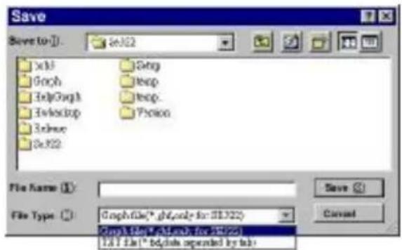
- Click the graph window you want to save and the graph window will become active, then choose File | Save from main menu or click from the tool bar.


- There will be a save dialog window for you to choose the file name and file type to save.There are three types of file name you can choose, binary file(*.ghf), text file(*.txt) and EXCEL format file(*.csv). The *.ghf file use much fewer disk space to save the data than the other two file format, but it can only be used in TestLink SE322. Text file can be opened by TestLink SE322 and any other word processor program like word, notepad etc. EXCEL format file can be opened by TestLink SE322 and Microsoft EXCEL.
(3.) How to load the recorded data from the memory of Sound Level Meter and save it to a file?
(Only for the model with Data Logger)
- Power on the Sound Level Meter.
- Press the REC button of the meter to start recording data.
-
After a while, press REC button again to stop recording data.
-
Connect the Sound Level Meter to PC
-
Start SE322 program.
- Choose Data Logger from main menu or click from tool bar.

- In reference to Data Logger, see DataLogger.
β Frequently Asked Question
- I had connected Sound Level Meter to PC serial port and turned meter power on, but it still show "NO CONNECTION".
Answer: It could be that all serial port are occupied by other application, close all other application. If it still don't work. Restart your computer and run TestLink SE322 again.
- How can I save the graph to a file which can be used in EXCEL?
Answer: When you save a graph to a file, the default file format is "*.ghf" and you can select *.csv to save files. CSV is an EXCEL file format. You can open it in EXCEL.
- How to uninstall TestLink SE322?
Answer: Uninstall TestLink SE322 by launching the Add/Remove Programs applet out of the Control Panel, highlighting the SE322, and clicking on the Add/Remove... push button, then it will remove the SE322 folder and files from your computer.
- Why loading data fail?
Answer: This might cause by the slow respond from some of the notebook PC system.
- How to zoom the graph?
Answer: Press the left mouse button and drag the cursor to select the new extents, then release the mouse button.
- When I setup the real time sampling with a fast rate (eg. 0.1 sec), Some of the sampling data might be lost.
Answer: This might be caused by slow response time of the PC.
- WINDSCHUTZ
- SCHALTFLÄCHEN
- SAFETY INFORMATION
- ENVIRONMENT CONDITIONS
- MAINTENANCE & CLEARING
- SAFETY SYMBOLS
- CE COMPLY WITH EMC
- GENERAL DESCRIPTION
- NOTE1
- SPECIFICATIONS
- NAME AND FUNCTIONS
- WINDSCREEN
- DISPLAY
- SYMBOL
- FUNCTION
- OVER
- UNDER
- 88-180
- POWER & BACKLIGHT BUTTON
- MAX / MIN HOLD BUTTON
- RECORD DATALOGGER BUTTON
- FREQUENCY WEIGHTING SELECT BUTTON
- TIME WEIGHTING SELECT BUTTON
- LEVEL RANGE CONTROL BUTTON
- MICROPHONE
- CAL POTENTIOMETER
- RS-232 INTERFACE
- SIGNAL OUTPUT TERMINAL
- EXTERNAL DC 9V POWER SUPPLY TERMINAL
- TRIPOD MOUNTING SCREW
- BATTERY COVER
- DATA LOGGER CLOCK & INTERVAL SETUP
- Β DATALOGGER
- Β CLOCK SETUP
- Β RECORDING INTERVAL SETUP
- Β AUTO POWER OFF
- CALIBRATION PROCEDURES
- MEASUREMENT PREPARATION
- BATTERY LOADING
- BATTERY REPLACEMENT
- AC ADAPTER CONNECTION
- OPERATING PRECAUTIONS
- MEASUREMENT
- SETUP TESTLINK SE-322 (SOUND LEVEL METER)—RS232 INTERFACE SOFTWARE
- Ü THE TESTLINK PACKAGE CONTAINS
- Ü SYSTEM REQUIRED
- Ü MINIMUM HARDWARE REQUIRED
- Β INSTALL TESTLINK
- Β MAIN MENU
- GRAPH
- TOOL BAR
- DATALOGGER
- Β TUTORIAL - QUICK START TO USE SE322 TESTLINK
- (1.) RECORDING REAL TIME DATA IN WAVEFORM
- (2.) HOW TO SAVE THE RECORDED REAL TIME DATA TO A FILE
- Β FREQUENTLY ASKED QUESTION
Brand : TFA
Model : 31.2000
Category : Sound Level Meter