0220 E 69 03 (HO) - Model making Brawa - Free user manual and instructions
Find the device manual for free 0220 E 69 03 (HO) Brawa in PDF.


| Product Type | Electric Locomotive Model |
| Scale | HO (1:87) |
| Model Number | 0220 E 69 03 (DC) / 0221 (AC) |
| Power Supply | Direct Current (DC) or Alternating Current (AC), switchable via circuit board |
| Motor Type | DC motor with two motors (prototype), model motor replaceable |
| Digital Decoder | Compatible with DGL 750 (Uhlenbrock) for AC version; DC version accepts standard decoder |
| Lighting | Direction-dependent function outputs; bulbs replaceable |
| Pantograph | Replaceable, two variants for catenary or subline operation |
| Couplings | Loosely enclosed: imitation couplings and air hoses |
| Maintenance | Lubrication points on motor and wheel sets; detailed disassembly instructions |
| Spare Parts | Comprehensive spare parts list with order example (pages 20-22) |
| Safety | Read instructions before work; caution with electrical components; consult specialist dealer |
| Prototype History | Built 1912 by Siemens/Krauss; service on Murnau-Oberammergau line |
| Weight (Model) | Approx. 250 g (typical HO locomotive) |
| Length (Model) | Approx. 200 mm (HO scale prototype length) |
Frequently Asked Questions - 0220 E 69 03 (HO) Brawa
User questions about 0220 E 69 03 (HO) Brawa
0 question about this device. Answer the ones you know or ask your own.
Ask a new question about this device
Download the instructions for your Model making in PDF format for free! Find your manual 0220 E 69 03 (HO) - Brawa and take your electronic device back in hand. On this page are published all the documents necessary for the use of your device. 0220 E 69 03 (HO) by Brawa.
USER MANUAL 0220 E 69 03 (HO) Brawa
natural_image
Black-and-white photo of a vintage electric locomotive on tracks, with mountainous background (no visible text or symbols)Operating Instructions Direct current model 0220 Alternating current model 0221
At the end of its long working life, E 69 03 has been a showpiece in the Garmisch engine shed. Its regular route where it started service in 1913 was from Murnau to Oberammergau.
The line from Murnau to Oberammergau of the local railway AG LAG was the first railway line in Germany to operate with single phase AC current (5000 V at a frequency of 16 Hz). Passenger traffic was handled by motor coaches, but a locomotive, LAG 1, was responsible for goods traffic. Thanks to the positive traffic development, locomotives LAG 2 and LAG 3 were also taken into service in 1909 and 1912. In 1938 when the Deutsche Reichsbahn took over LAG, the two locomotives were given the operation numbers E 69 02 and E 69 03.
E 69 03 was built by Siemens and Krauss. With a service weight of 24 tons, the locomotive had two motors with an output of 126 kW each. On account of the huge increase in traffic, E 69 03 later was fitted with stronger motors of 176 kW each. In order to make space for the corresponding electric equipment and to reinforce the locomotive, a supplementary frame was inserted between the locomotive frame and the superstructure. Up until 1953, it operated just on its regular route, and was then later also used in Rosenheim and Heidelberg.
Removing the locomotive from the packaging 6
Fitting additional parts 6
Maintenance works
• 1. Lubricating .... 7
• 2. Switch from cat wire to sub-line ..... 7
• 3. Dismantling the housing ..... 10, 11
• 4. Exchanging the motor .... 10, 11
• 5. Exchanging the circuit board ..... 10, 11
- 6. Exchanging the bulb .... 10, 11
• 7. Exchanging the digital decoder ..... 10, 11
- 8. Exchanging the sliding contact of the Alternating Current Version .... 10, 11
- 9. Maintenance work on wheel sets, gearing and standard coupling shaft .... 10, 11
• 10. Exchanging the pantograph.... 10, 11
• 11. Converting for digital operation ..... 16, 17, 18, 19
Spare parts list
direct current and alternating current 20, 21, 22
Order example 22
General assembly and safety information
• These operating instructions describe all work steps necessary for maintenance and repair. Please read these operating instructions carefully before you start with your work.
- In the case of incorrect handling of electrical components, they may be destroyed. Please ask your specialist dealer to help with the necessary work (e.g. changing circuit boards).
- In the case of maintenance work, the disassembly is described below, to re-assemble the tractor reverse the work steps.
- The maintenance work described below is virtually identical for direct current and alternating current models. If there are any differences these will be pointed out specifically.
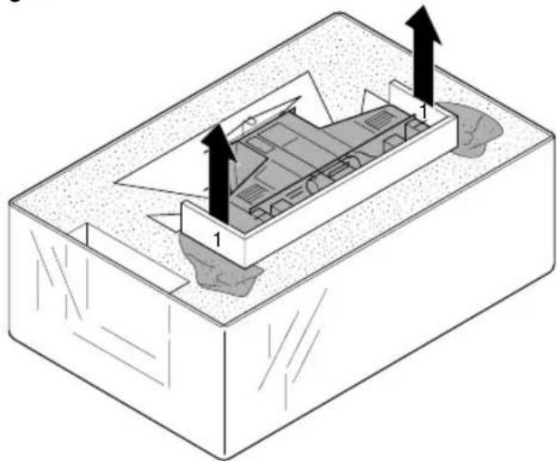
Removing the engine from the packaging (Fig. 1)
Open the lid of the packaging.
Press the foam down using the tabs (1) securing the engine during transport, then pull the engine out with these tabs.
Fig. 1
natural_image
Isometric diagram of a mechanical or structural component with two numbered parts and directional arrows indicating flow or movement (no text or symbols present)2 = 2 x Luftschlauch links
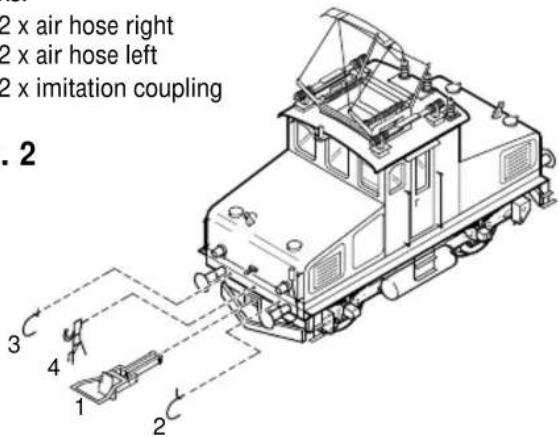
Fitting additional parts (Fig. 2)
Accessory parts have been loosely enclosed in the packaging. 1 = 2 x Coupling
If parts contained in the setting-up bag for showcase models are fitted, the locomotive is no longer suitable for running on tracks.
2 = 2 x air hose right
3 = 2 x air hose left
4 = 2 x imitation coupling
Fig. 2
text_image
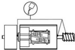
2 x air hose right 2 x air hose left 2 x imitation coupling . 2 3 4 1 2The motor and the wheelset bearings may be sparingly lubricated at the marked places with oil used for model making purposes. In order to lubricate the motor, remove the housing and the gearbox cover, compare page 10, item 3 and 4.
Fig. 3
Motor Motor
natural_image
Pure mechanical diagram showing internal components without any text, numbers, or symbolsRäder Wheels
natural_image
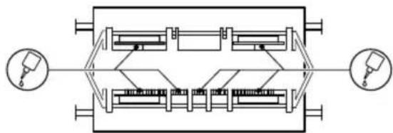
Pure electrical circuit lines without any symbols2. Switching from subline to cat wire (Fig. 4)
The Engine is delivered for subline operation. For cat wire operation, the switch (on the circuit board) must be turned by 90 degrees after taking off body (compare page 10, item 3).
Fig. 4
natural_image
Pure electrical circuit lines without any symbolsnatural_image
Pure electrical circuit lines without any symbolsWartungsarbeiten
text_image
Exploded view diagram of a device with numbered parts and labeled features such as motors, batteries, and accessories.Maintenance works
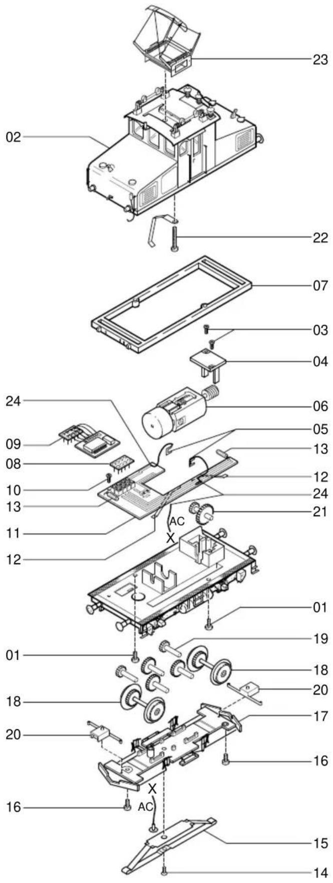
3. Dismantle housing (fig. 5)
Unscrew 2 screws (1) on the bottom of the housing and lift housing (2) off.
4. Replace motor (fig. 5)
Remove housing, see point 3. Unscrew fastening screws (3), lift off gear cover (4). Remove contact plates (5) from motor. Remove motor (6).
Note:
When removing the motor, pay attention to the installation position, otherwise wrong direction of travel.
5. Replace the printed circuit board (fig. 5)
Remove housing, see point 3.
Remove frame (7), pull off dummy connector (8) for DC version or digital decoder (9) for AC version. Unscrew fastening screw (10), lift off printed circuit board (11), unsolder cable (24) on the top of the printed circuit board.
Note:
The contact plates (12) of the printed circuit board must lie on the wheelsets during assembly.
6. Replace the light bulbs (fig. 5)
Remove housing, see point 3.
Unsolder light bulb (13) from the upper side of the printed circuit board, solder on new light bulb accordingly.
7. Replacing the digital decoder (fig. 5)
Remove housing, see point 3.
Pull off digital decoder (9) and insert new digital decoder.
8. Replace the trailer for AC version 0221 (fig. 5)
Unscrew fastening screw (14) of trailer (15), take off trailer.
9. Maintenance work on wheelsets, gear and coupling norm shaft (fig. 5)
Turn the locomotive over so that the wheels and gear plate point upwards. Unscrew the screws (14 and 16), remove gear plate (17), remove wheelsets (18) and gear wheels (19).
Remove coupling norm shaft.
Remove worm wheel:
Dismantle housing and motor, see points 3 and 4.
The worm wheel (21) can be lifted out.
10. Change the pantograph (fig. 5)
Remove housing, see point 3.
Unscrew the screw (22) inside the housing and remove pantograph (23).
Fig. 5
text_image
Exploded view diagram of a mechanical device with numbered parts and labeled features such as motors, batteries, and wheels.11. Converting and reprogramming for digital operation
Version: Direct Current 0220
Remove housing (2), pull off dummy plug (8) and plug in digital decoder (9) (see page 10, 11).
Please consult the decoder manufacturer's mounting instructions for the correct installation of the digital decoder and its plug-in direction.
After the digital decoder has been plugged in, check whether the light is functioning. If there is no light function – turn plug by 180^ and plug-in again.
Version: Alternating Current 0221
This locomotive is supplied with the DGL 750 digital decoder made by Uhlenbrock. Consequently, the locomotive does not have to be converted, only reprogrammed. When delivered, the decoder is programmed for analog operation.
Reprogramming from analog to digital operation
Reprogramming must be completed according to the flow chart (see page 18/19).
Note:
If the locomotive no longer reacts after reprogramming, then the locomotive address has probably been reprogrammed. Incorrect entries can be corrected by resetting the values with the function 10 (Reset) to the original digital position, i.e. locomotive address 01, starting and braking 01.
Properties
Locomotive decoder with two direction-dependent function outputs for DC motors in the Märklin-Motorola format.
- Can be programmed by Intellibox of Control 80.
- The Intellibox can access 255 addresses, other digital devices 80 addresses.
- 2 different addresses per decoder possible.
- Locomotive addresses, minimum travel voltage, acceleration, maximum speed and delay can be entered as required.
- All values are saved permanently.
- Pre-set to address 01 and digital operation.
Digital operation
In digital operation, the locomotive runs with the parameters you have entered. These are permanently saved together with direction of travel and speed. This means that when the system is switched on again, a locomotive continues to travel at the last set speed. In this way, the locomotive can also be used in block system. If the locomotive in digital operation travels on an analogue section, you keep the digitally set speed as long as sufficient voltage is available. It is not possible to change the direction of travel or increase the travel speed in analogue sections.
Analogue operation
In analogue operation, the decoder behaves like a direction switch. The locomotive stops on a digital section.
Selecting the operating mode
There are various methods of changing over between digital and analogue mode of the decoder.
You can bring the locomotive with the digital decoder to an
analogue piece of track and put the drive switch of the transformer in the change-over position. After a short time the decoder then changes over to the other mode: from digital to analogue after 4 seconds, from analogue to digital after 8 seconds.
The vehicle flashes the rear lights to indicate that the changeover has taken place. Alternatively, the decoder can be programmed with function 08 to analogue (value = 01) or digital (value = 02). (The decoder can also be programmed in the analogue operating mode, because it recognises the digital voltage on the piece of track).
Note:
The lighting status adjusted in digital mode is retained in analogue mode. In other words, if the travelling lights are switched off in digital mode, they remain off in the analogue mode.
Compatibility
The module is compatible with the approach braking circuit for the C90 by Märklin.
Technical data
Addresses: 1 – 255, all accessible via the Intellibox
1 – 80 when another central unit is being used
Max. engine current: 700 mA when the module is placed loosely in the locomotive or fastened with an adhesive pad; 1 A when the module is adhered to the chassis with hot or thermal adhesive
Motor starting current: briefly up to 2 A
Function outputs: 900 mA each
Size: 19 x 16 x 5 mm
Programming using the Intellibox
The easiest way of programming Uhlenbrock decoders is to use the Intellibox. The programming mode provides plain text user guidance through the menu. The exact programming procedure is described in chapter 9 of the Intellibox manual.
Programming using Loktool
You can programme the decoders in an extremely easy and convenient manner using our program "Loktool" for Windows on a PC from 386-25 MHz with connected interface 6050/6051 under Windows 3.x, 95 or NT.
Programming using the Märklin central unit
Connect your control 80/80f to the central unit (6035/6036 + 6020) or connect the control unit (6021) to a section of track which has only the locomotive being programmed standing on it.
To program the module, always proceed in the sequence described on the right. Do not press any other keys.
If the locomotive fails to react after a programming sequence, then the locomotive address has probably been reprogrammed. Try out all addresses in succession to see when your vehicle reacts, or use the search function of the Intellibox or the Loktool program (see the last page). Mistakes can be corrected by using function 10 to restore the delivered status, i.e. locomotive address 01, starting and braking 01.
Programming Uhlenbrock decoders
Switch transformer off for 10 There is no more interfering
Select locor This is 01 for e
Press the direction changeover key for 8 seconds. This is confirmed by a lamp on t
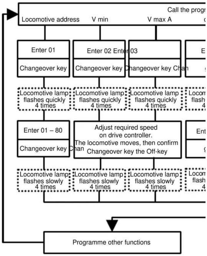
flowchart
graph TD
    A["Locomotive address"] --> B["Enter 01"]
    B --> C["Changeover key"]
    C --> D["Locomotive lamp flashes quickly 4 times"]
    D --> E["Enter 01 - 80"]
    E --> F["Changeover key"]
    F --> G["Locomotive lamp flashes slowly 4 times"]
    G --> H["Programme other functions"]
    H --> I["Locomotive lamp flashes slowly 4 times"]
    I --> J["Locomotive lamp flashes quickly 4 times"]
    J --> K["Adjust required speed on drive controller. The locomotive moves, then confirm Chan Changeover key the Off-key"]
    K --> L["Locomotive lamp flashes slowly 4 times"]
    L --> M["Locomotive lamp flashes quickly 4 times"]
    M --> N["Locomotive lamp flashes quickly 4 times"]
    N --> O["Locomotive lamp flashes quickly 4 times"]
    O --> P["Locomotive lamp flashes quickly 4 times"]
    P --> Q["Locomotive lamp flashes quickly 4 times"]
    Q --> R["Locomotive lamp flashes quickly 4 times"]
    R --> S["Locomotive lamp flashes quickly 4 times"]
    S --> T["Locomotive lamp flashes quickly 4 times"]
    T --> U["Locomotive lamp flashes quickly 4 times"]
    U --> V["Locomotive lamp flashes quickly 4 times"]
    V --> W["Locomotive lamp flashes quickly 4 times"]
    W --> X["Locomotive lamp flashes quickly 4 times"]
    X --> Y["Locomotive lamp flashes quickly 4 times"]
    Y --> Z["Locomotive lamp flashes quickly 4 times"]
    Z --> AA["Locomotive lamp flashes quickly 4 times"]
    AA --> AB["Locomotive lamp flashes quickly 4 times"]
    AB --> AC["Locomotive lamp flashes quickly 4 times"]
    AC --> AD["Locomotive lamp flashes quickly 4 times"]
    AD --> AE["Locomotive lamp flashes quickly 4 times"]
    AE --> AF["Locomotive lamp flashes quickly 4 times"]
    AF --> AG["Locomotive lamp flashes quickly 4 times"]
    AG --> AH["Locomotive lamp flashes quickly 4 times"]
    AH --> AI["Locomotive lamp flashes quickly 4 times"]
    AI --> AJ["Locomotive lamp flashes quickly 4 times"]
    AJ --> AK["Locomotive lamp flashes quickly 4 times"]
    AK --> AL["Locomotive lamp flashes quickly 4 times"]
    AL --> AM["Locomotive lamp flashes quickly 4 times"]
    AM --> AN["Locomotive lamp flashes quickly 4 times"]
    AN --> AO["Locomotive lamp flashes quickly 4 times"]
    AO --> AP["Locomotive lamp flashes quickly 4 times"]
    AP --> AQ["Locomotive lamp flashes quickly 4 times"]
    AQ --> AR["Locomotive lamp flashes quickly 4 times"]
    AR --> AS["Locomotive lamp flashes quickly 4 times"]
    AS --> AT["Locomotive lamp flashes quickly 4 times"]
    AT --> AU["Locomotive lamp flashes quickly 4 times"]
    AU --> AV["Locomotive lamp flashes quickly 4 times"]
    AV --> AW["Locomotive lamp flashes quickly 4 times"]
    AW --> AX["Locomotive lamp flashes quickly 4 times"]
    AX --> AY["Locomotive lamp flashes quickly 4 times"]
    AY --> AZ["Locomotive lamp flashes quickly 4 times"]
    AZ --> BA["Locomotive lamp flashes quickly 4 times"]
    BA --> BB["Locomotive lamp flashes quickly 4 times"]
    BB --> BC["Locomotive lamp flashes quickly 4 times"]
    BC --> BD["Locomotive lamp flashes quickly 4 times"]
    BD --> BE["Locomotive lamp flashes quickly 4 times"]
    BE --> BF["Locomotive lamp flashes quickly 4 times"]
    BF --> BG["Locomotive lamp flashes quickly 4 times"]
    BG --> BH["Locomotive lamp flashes quickly 4 times"]
    BH --> BI["Locomotive lamp flashes quickly 4 times"]
    BI --> BJ["Locomotive lamp flashes quickly 4 times"]
    BJ --> BK["Locomotive lamp flashes quickly 4 times"]
    BK --> BL["Locomotive lamp flashes quickly 4 times"]
    BL --> BM["Locomotive lamp flashes quickly 4 times"]
    BM --> BN["Locomotive lamp flashes quickly 4 times"]
    BN --> BO["Locomotive lamp flashes quickly 4 times"]
    BO --> BP["Locomotive lamp flashes quickly 4 times"]
    BP --> BQ["Locomotive lamp flashes quickly 4 times"]
    BQ --> BR["Locomotive lamp flashes quickly 4 times"]
    BR --> BS["Locomotive lamp flashes quickly 4 times"]
    BS --> BT["Locomotive lamp flashes quickly 4 times"]
    BT --> BU["Locomotive lamp flashes quickly 4 times"]
    BU --> BV["Locomotive lamp flashes quickly 4 times"]
    BV --> BW["Locomotive lamp flashes quickly 4 times"]
    BW --> BX["Locomotive lamp flashes quickly 4 times"]
    BX --> BY["Locomotive lamp flashes quickly 4 times"]
    BY --> BZ["Locomotive lamp flashes quickly 4 times"]
    BZ --> CA["Locomotive lamp flashes quickly 4 times"]
    CA --> CB["Locomotive lamp flashes quickly 4 times"]
    CB --> CC["Locomotive lamp flashes quickly 4 times"]
    CC --> CD["Locomotive lamp flashes quickly 4 times"]
    CD --> CE["Locomotive lamp flashes quickly 4 times"]
    CE --> CF["Locomotive lamp flashes quickly 4 times"]
    CF --> CG["Locomotive lamp flashes quickly 4 times"]
    CG --> CH["Locomotive lamp flashes quickly 4 times"]
    CH --> CI["Locomotive lamp flashes quickly 4 times"]
    CI --> CJ["Locomotive lamp flashes quickly 4 times"]
    CJ --> CK["Locomotive lamp flashes quickly 4 times"]
Decoder manual
Comprehensive technical information about our digital decoders is available from your retailer, including extended programming instructions (speed curves, possibilities for function keys, 3^rd locomotive address).
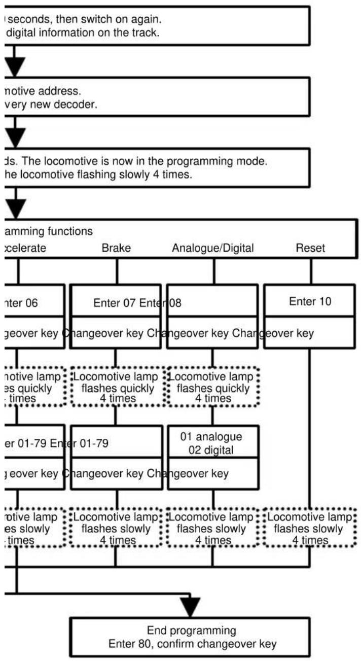
flowchart
graph TD
    A["seconds, then switch on again.<br>digital information on the track."] --> B["notive address.<br>very new decoder."]
    B --> C["ds. The locomotive is now in the programming mode.<br>he locomotive flashing slowly 4 times."]
    C --> D["amming functions<br>xcelerate"]
    D --> E["Enter 06<br>geover key"]
    D --> F["Enter 07 Enter 08<br>Changeover key"]
    D --> G["Enter 10<br>geover key"]
    E --> H["notive lamp<br>es quickly<br>times"]
    F --> I["Locomotive lamp<br>flashes quickly<br>4 times"]
    G --> J["Locomotive lamp<br>flashes quickly<br>4 times"]
    H --> K["01 analogue<br>02 digital"]
    I --> K
    J --> K
    K --> L["notive lamp<br>es slowly<br>times"]
    L --> M["Locomotive lamp<br>flashes slowly<br>4 times"]
    M --> N["Locomotive lamp<br>flashes slowly<br>4 times"]
    N --> O["End programming<br>Enter 80, confirm changeover key"]
    O --> D
    style A fill:#f9f,stroke:#333
    style B fill:#f9f,stroke:#333
    style C fill:#f9f,stroke:#333
    style D fill:#ccf,stroke:#333
    style E fill:#cfc,stroke:#333
    style F fill:#cfc,stroke:#333
    style G fill:#cfc,stroke:#333
    style H fill:#fcc,stroke:#333
    style I fill:#fcc,stroke:#333
    style J fill:#fcc,stroke:#333
    style K fill:#fcc,stroke:#333
    style L fill:#fcc,stroke:#333
    style M fill:#fcc,stroke:#333
    style N fill:#fcc,stroke:#333
    style O fill:#fcc,stroke:#333
Ersatzteilliste Lokomotive E 69 03 Spare Parts List locomotive E 69 03
D.C. current / A.C. current
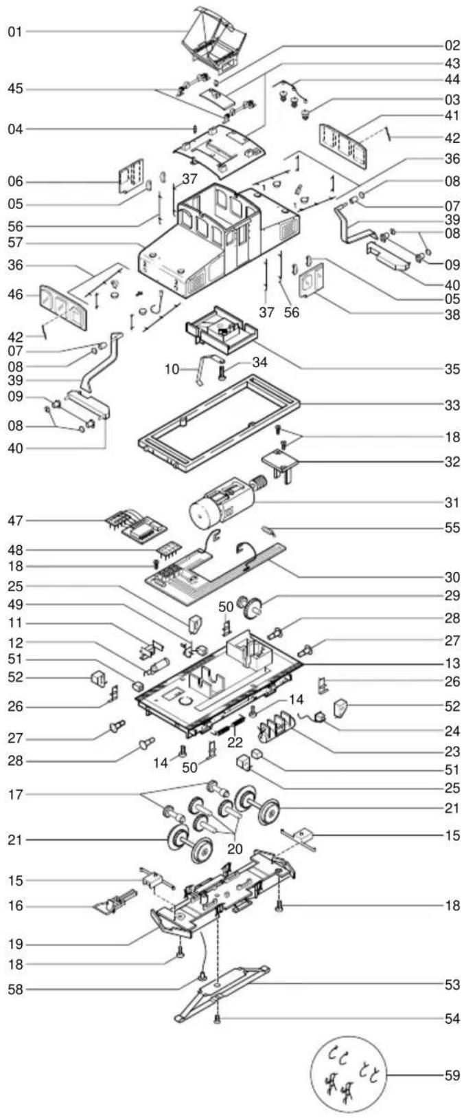
text_image
Exploded view diagram of a vehicle's internal components with numbered parts and Chinese labelsMotor complete with position 31 = 0220.50.60 Motor complete
natural_image
Technical line drawing of a locomotive cab with suspension components and roof structure (no text or symbols)