
62701 Gravita 10 BB - Model making Brawa - Free user manual and instructions
Find the device manual for free 62701 Gravita 10 BB Brawa in PDF.


User questions about 62701 Gravita 10 BB Brawa
0 question about this device. Answer the ones you know or ask your own.
Ask a new question about this device
Download the instructions for your Model making in PDF format for free! Find your manual 62701 Gravita 10 BB - Brawa and take your electronic device back in hand. On this page are published all the documents necessary for the use of your device. 62701 Gravita 10 BB by Brawa.
USER MANUAL 62701 Gravita 10 BB Brawa
natural_image
Black-and-white exterior view of a Voith Turbo locomotive (no visible text or symbols on the vehicle body)Diesel locomotive Gravita 10 BB
For over 70 years, the Voith company of Heidenheim has been a supplier of vehicle parts, especially high-performance hydraulic transmissions. For the first engine developed completely in-house, the new company Voith Turbo Lokomotivtechnik GmbH & Co KG was founded, with headquarters in Kiel. The first engine, christened the Maxima 40 CC, had its public debut in 2006.
With an output of 3600 kW, it is the strongest single-engine diesel-hydraulic locomotive. Since it was designed from the outset as a modular family, the vehicle is also available in a different performance class as the Maxima 30 CC and Maxima 20 BB.
Despite the risk, a large number of orders were placed relatively quickly. This encouraged Voith in the project of developing a modular locomotive family for shunting and light line service.
A high demand is expected in this area for the next few years, as many older locomotives are due for replacement and diesel traction is preferred, especially in shunting service. After a short development time, Voith Lokomotivtechnik presented the first sample of the Gravita family at InnoTrans 2008. Five different performance classes are projected, from the four-axle Gravita 20 BB to the „chicks“, which go by the name Gravita 5 BB and which have only two axles. Although the vehicle had only existed as a prototype and was not yet widely tested, DB Schenker decided on more than 130 locomotives for the Gravita 10 BB in its 2007 bid invitation.
By now, the first units of the Gravita 10 BB are in use on the Northrail on German rail tracks. The designated DB machines are currently in production and will soon be seen in use nationwide under the series designation BR 260.
Apart from Northrail, another 5 locomotives went to Switzerland. Continuing this success, the next larger sister in this series, the Gravita 15 BB, was shown in Berlin in 2010. Although only 1.2 m longer than the Gravita 10 BB, it produces up to 1,800kW, making it as suitable for line service as it is for shunting. All locomotives built by Voith Turbo Lokomotivtechnik are also suited for multi-led traction with each other. The engine assembled under the serial number L04-15 001 is being exhaustively tested at present.

Scale and true to original small-sized model for adult collectors.


Only a toy transformer produced compliant with VDE 0551/EN 60742 may be used as a voltage source to operate this product.

Electrical equipment may not reach to domestic waste. According to the current terms of the country reference the electrical equipment must professional disposed.

Benennung Seite
- General assembly and safety information ....4
- Fitting additional parts ....5
• Function keys for sound models .....5 -
Maintenance works
-
Removing the housing 6
- Removing the PCB, Decoder installation ....6
- Exchanging the motor, dismantling drive screw 6
- Removing the bogie, dismantling wheels, replacing gear wheels ....6
- Replacing traction tire ....7
-
Lubricating ....7
-
Spare parts list ......9
- Order example ....11
General assembly and safety information
- These operating instructions describe all work steps necessary for maintenance and repair. Please read these operating instructions carefully before you start with your work.
- In the case of incorrect handling of electrical components, they may be destroyed. Please ask your specialist dealer to help with the necessary work (e.g. changing circuit boards).
- In the case of maintenance work, the disassembly is described below, to re-assemble the tractor reverse the work steps.
- When dismantling the engine make a note of the mounted position of the individual parts. An incorrectly mounted part can be destroyed or operation can be disrupted.
- All cables and connection wires installed in this product may not be inserted in a mains socket. Danger!
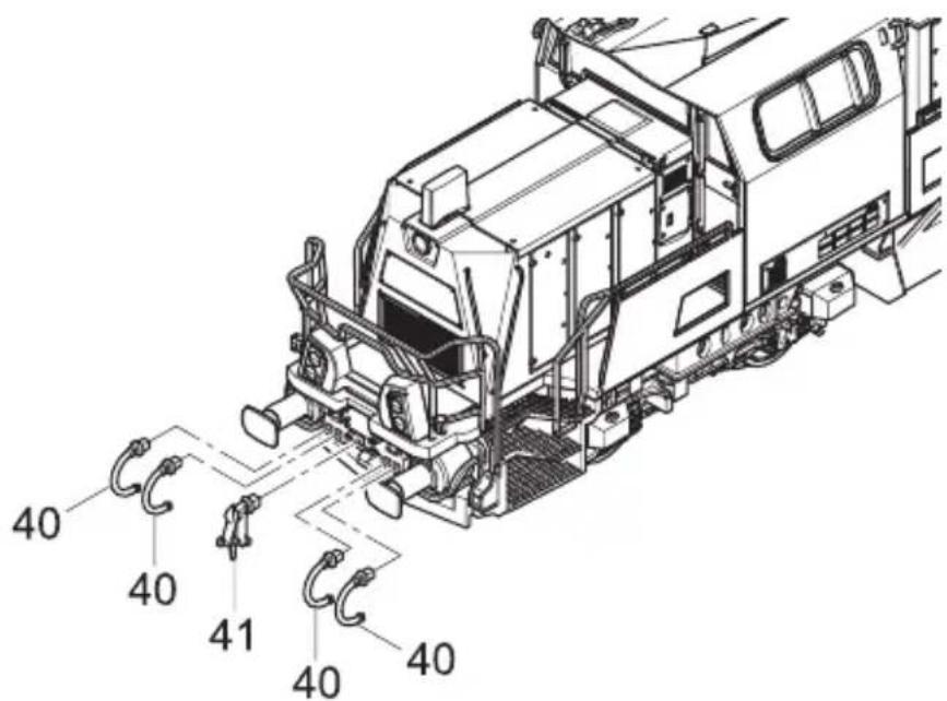
Fitting additional parts (fig. 1)
If additional parts for showcase models are fitted, the locomotive is no longer suitable for running on tracks.
Pos. Description Required number
| 40 Brake tube 8 |
| 41 Coupling hook 2 |
Fig. 1 / fig. 1
text_image
40 40 41 40 40Function keys for sound models
The locos 62713, 67215 and 62717 have a sound decoder onboard. You can download the function key assignment at www.brawa.de
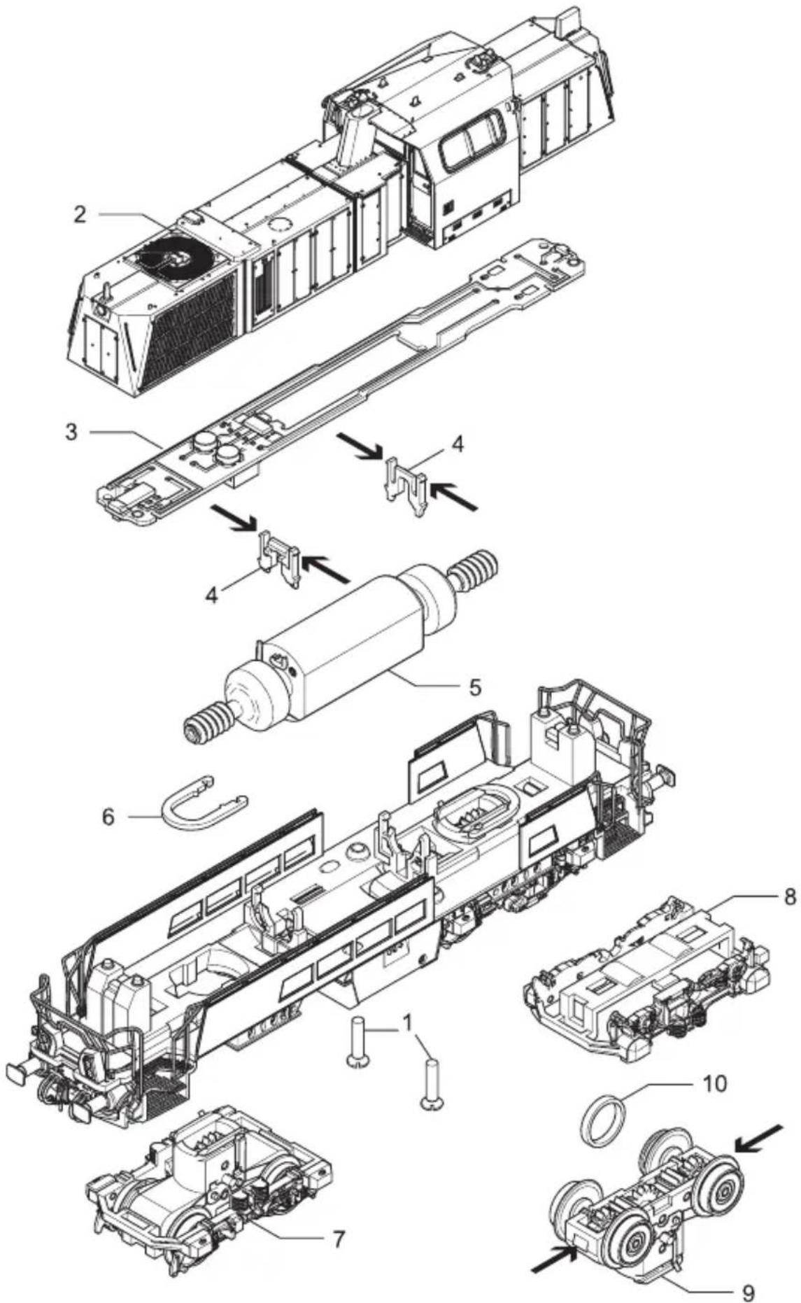
1. Removing the housing (fig. 3)
Remove flat head screws (01) at the bottom and detach the chassis (02) upwards.
2. Removing the PCB,
Decoder installation (fig. 3)
Demount chassis, (watch point 1). Detach the clip-fixation of the PCB (03) from the motor clips (05) and remove the PCB. Plug the decoder into interface (04). The plug in direction is marked after NEM 651 with number 1.
2. Exchanging the motor, dismantling drive screw (fig. 3)
Remove the housing, see item 1. Remove the PCB, see item 2.
- Exchanging the motor
Remove motor clip-fixation (05) in worm gear direction and pull upwards. Remove motor (06) from motor mounting. Unsolder the cable at the motor. Pay attention to the cable position when unsoldering, otherwise the travelling direction will be wrong.
4. Removing the bogie, dismantling wheels and replacing gear wheels (fig. 3)
Remove the housing, see item 1. Remove the PCB, see item 2. Exchanching the motor, see item 3.
- Bogie uninstall
Push/pull the bogie holder (07) and unfix it. Remove loco chassis carefully upwards.
- Dismantling wheels and replacing gear wheels
Turn bogie (08) upside down and remove the clip-fixation from the bogie frame (09) and the chassis (10). Remove the bogie frame. Remove wheels and gear wheels and replace them.
5. Replacing traction tire (fig. 3)
For a tracion tire replacement, the loco must not be disassambled totally.
Turn loco upside down and remove the clip-fixation from the bogie frame (09) and the chassis (10). Remove bogie frame. Remove and replace the tracion tires.
6. Lubricating (fig. 2)
The motor and the wheelset bearings may be sparingly lubricated at the marked places with oil used for model making purposes. In order to lubricate the motor, remove the housing and the PCB, compare page 5, item 1 and 2.
Fig. 2 / fig. 2
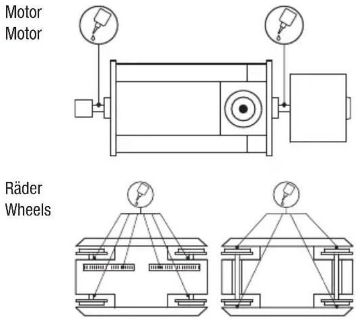
Fig. 3 / fig. 3
text_image
Exploded view diagram of a mechanical assembly with numbered components for identificationGleichstrom / D.C.current
vorn (1) / front (1)
hinten (2) / back (2)
text_image
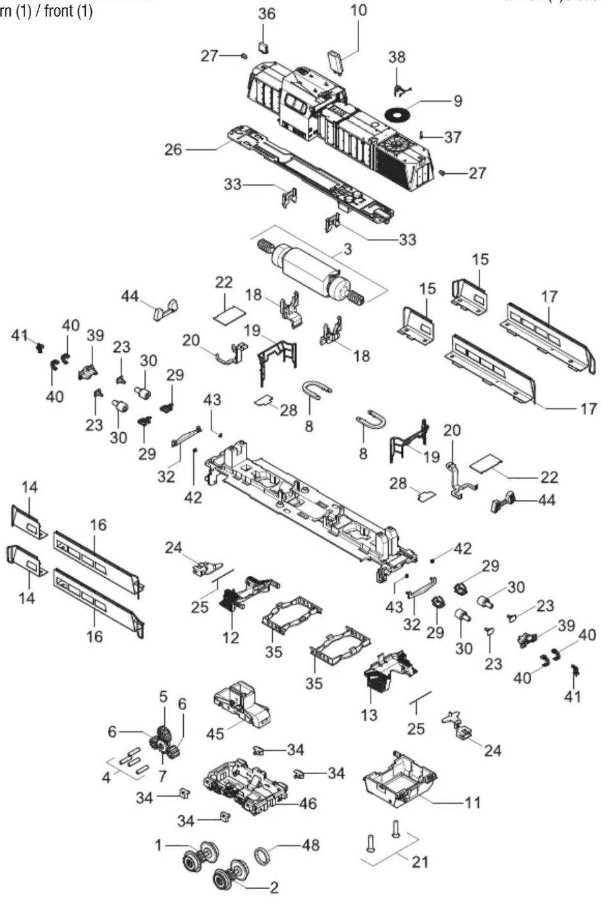
rn (1) / front (1)Position (23), Puffer = 0015047.00, Puffer
Important information:
To fit individual spare parts it is necessary to dismantle the loco. Please be careful not to damage any components during removal as not every component is available as spare part.
Order notice
When ordering spare parts you must always state the order number and give the description. If you do not do this, the order cannot be processed.
Order example:
Position (23), Buffer= 0015047.00, Buffer
LOKDECODER Gravita

Inhaltsverzeichnis
Electrical equipment may not reach to domestic waste. According to the current terms of the country reference the electrical equipment must professional disposed.
5. Funktionen
-
Introduction ......1
-
Safety instructions .....2
-
Warranty ......2
-
Support and Help ......2
-
Features ....3
-
Operating mode SelecTRIX 1 (SX1) 2 .....4
6.1 Features ....4
6.2 Configuration options .....4
6.3 Operation ....4
- Operation form DCC .....5
7.1 Features ....5
7.2 Configuration options ..6, 7
7.3 Operation 8,9
- Operation form SelecTRIX 2 (SX2) 5 ....8, 9
8.1 Features ....8, 9
8.2 Configuration options ..8, 9
8.3 Operation .....10
1. Introduction
The built-in decoder is compatible with the standard SelectRIX SX1, SX2, and the NMRA standard and works with all CPUs, which operate with the issue of these data formats.
The maximum operating voltage is 18V!
Operating on AC systems with switch pulse is not allowed!
The switching pulse leads to the destruction of the decoder!
2. Safety instructions
• This product is not recommended for children under 14 years!
- If used improperly, sharp edges and points may cause injury!
3. Warranty
Every decoder is tested to full function before delivery. However, an error occurs, please contact the dealer from whom you bought the decoder. The usual warranty period is 24 months.
4. Support and Help
See page 12.
Electrical equipment may not reach to domestic waste. According to the current terms of the country reference the electrical equipment must professional disposed.
5. Features
- For optional operation with a conventional direct-current driving device, digital systems according to SelectTRIX 1 and 2 or NMRA standard (DCC)
- Switching between analog and digital mode automatically
- In digital mode, the last programmed system is used (it is not switched automatically!)
- SelectRIX 1 31 speed steps, 100 addresses
- SelectTRIX 2 127 speed steps, 10.000 addresses, 16 additional functions
- DCC short addresses (1-127), long addresses (0001-9999), 14, 28, 126 speed steps
- Load control of the latest generation, especially in soft control
- Internal 127 speed steps
- Block operation with simple diodes in digital mode
- Shunting
• Temperature protection - Reset function for DCC and SX2
- Ability to update the decoder
6. Operating mode SelecTRIX 1 (SX1)
6.1 Features
- Speed steps 31
• Speed steps (internal) 127 - Light front / rear
• Additional features 2
• Additional channel shiftable - (Locomotive + 1) with 8 functions
6.2 Configuration options
All parameters of the locomotive can be changed as often as desired by programming. For information to program, read the manual of your programmer.
Basic settings
Address 3 (DCC)
Address 1 (SX1)
6.3 Operation
Place the locomotive on the programming track and read out the settings of the decoder. The default setting should be 01-542. Program the desired locomotive address and take the train with these setting into operation. After the first check, you can adjust the parameters of the engine to your needs.
7. Operation form DCC
7.1 Features
- Short addresses 1 – 127
- Long addresses 0001 - 9999
- Speed steps 14, 28, 126
• Speed steps (internal) 127
• Light front / rear (dimmable)
• Operation with brake diodes yes
• Operation with brake generators yes - Multiple traction yes
• Full NMRA compliant yes - Main track programming yes
Function classification:
F0 Light
F1 Driving noise
F2 Horn 1
(as long as pressed)
F3 Horn 2
(as long as pressed)
F4 Shunting
F5 Closing sound
Cab door
F6 Light off front
F7 Squealing brakes (manual)
F8 Light off back
F9 Low beam
F10-
F11 Horn (long) 1
F12 Horn (long) 2
F13 Horn 1 (short)
F14 Horn 2 (short)
F15 Release noise brake (manual)
F16 Fade
Twice white light on both sides can switched with F0 (Light) on, F6 on and F8 on. Twice red light on both sides, can switched with F0 (light) off, F6 on and F8 on.
7.2 Configuration options
The properties of the locomotive for DCC operation can be changed as often as desired by programming the „Configuration Variables“ (CV). For programming the CV read the documentation of your programming device.
Note:
If the decoder are programmed with other gears as the driving device, it may cause a malfunction. Note the references to the digital system.
List of the supported CV:
| CV Description Value range Default-Value | ||
| 01 Address 0-127 (3) | ||
| 02 Starting voltage 0-15 (0) | ||
| 03 Acceleration 0-255 (8) | ||
| The value corresponds to the time in seconds from a standstill up to top speed | ||
| 04 Braking time 0-255 (8) | ||
| The value corresponds to the time in seconds of the top speed to standstill | ||
| 05 Top speed 0-127 (92) | ||
| 07 Version number (read only) - - | ||
| 08 Manufacturer ID (read only) - (127)(Reset / Factory setting „8“) | ||
| 17 Advanced locomotive address 0-255 (192) | ||
| 18 - 0-255 (0) | ||
| CV17 contains the most significant byte, CV18 contains the low order byte. Only when activated by CV29 | ||
| 19 Consist address 0-255 (0) | ||
| Several locomotives in composite at this address0 = Inactive; Value + 128 = Inverse direction | ||
| 29 Configuration register 0-255 (6) | ||
| Bit Function Value | ||
| 0 Reverse Direction 1 | ||
| 1 14 - 28/126 Speed steps 2 | ||
| 2 Analog mode allows 4 | ||
| 5 Locomotive address after CV17/18 32 | ||
| 930 Overall volume 0-255 (192) | ||
| 0 = 0% ... 128 = 50% ... 255 = 100% | ||
All programmable parameters except CV01, CV17 + CV18
(= Locomotive address) can be changed during operation (POM / Programming On the Main / Main track programming).
7.3 Operation
Place the locomotive on the programming track and read out the locomotive address from the decoder (CV01). The default setting should be 03. Program the desired locomotive address and take the train with these setting into operation. After the first check, you can adjust the parameters of the engine to your needs.
Note:
The DC operation in the braking section is at the default setting not possible. If this feature is desired, CV29 / Bit 2 must be set to „1“.
8. Operation form
SelecTRIX 2 (SX2)
8.1 Features
- Speed steps 127
• Speed steps (internal) 127
• Operation with brake diodes yes - Main track programming yes
8.2 Configuration options
The features of the locomotive for SX2 operation can be changed as often as desired by programming the parameters (par). For programming the parameters read the documentation of your programming device.
List of the supported parameters:
| par Description Value range Default-Value | ||
| 001 Address unit digit 0-99 (1) | ||
| 002 Address hundreds digit 0-99 (10) | ||
| 003 Address for SX1 0-255 (112) | ||
| At > 111 inactive | ||
| 004 Address for SX1, 1. extra channel 0-255(1)Functions F1 – F8 | ||
| 005 Adresse für SX1, 2. extra channel 0-255(0)Functions F9 – F16 | ||
| 006 Locomotive address read out 0, 1 | (1) | |
| 007 Mode of operation extra channel 0, 1 | (0) | |
| 0 = relative:1. Extra channel = par003 + par0042. Extra channel = par003 + par0051 = absolutely | ||
| 011 Acceleration time 0-255 (8) | ||
| The value corresponds to the time in seconds of the top speed to standstill | ||
| 012 Braking time | 0-255 (8) | |
| The value corresponds to the time in seconds of the top speed to standstill | ||
| 013 Top speed | 0-127 (127) | |
| 014 Starting voltage | 0-15 (0) | |
| 101 Manufacturer ID (read only) | – | (97) |
| (Decoder Reset with „101“) | ||
All programmable parameters except par001 + par002 (= ID-address) can be changed during operation (POM / Programming On the Main / Main track programming).
8.3 Operation
Place the locomotive on the programming track and read out the locomotive address from the decoder (par001+ par002). The default setting should be 1001. Program the desired locomotive address and take the train with these setting into operation. After the first check, you can adjust the parameters of the engine to your needs.
Note

Brawa Artur Braun