
G3-PRO - Security Camera Ubiquiti Networks - Free user manual and instructions
Find the device manual for free G3-PRO Ubiquiti Networks in PDF.


| Type de produit | Camera de securite IP |
| Marque | Ubiquiti Networks |
| Modele | G3-PRO (UVC-G3-PRO) |
| Dimensions (sans plaque de montage) | ∅ 86 x 153 mm (∅ 3.39 x 6.02 po) |
| Poids (sans plaque de montage) | 700 g (1.54 lb) |
| Alimentation | IEEE 802.3af/802.3at PoE, 48V 0.5A, consommation max 12.5W |
| Resolution video | 1080p Full HD (1920 x 1080), jusqu'a 30 FPS |
| Compression video | H.264 |
| Objectif | 3-9 mm, f/1.2-f/2.1, zoom motorise |
| Champ de vision | Grand-angle : 108° (H) x 58° (V) x 125° (D) ; Tele : 37° (H) x 20° (V) x 43° (D) |
| Vision nocturne | LEDs IR avec filtre IR mecanique |
| Microphone | Integre |
| Interface reseau | Port Ethernet 10/100 RJ45 |
| Gestion | UniFi Video v3.9 ou plus recent, interface web integree (mode autonome) |
| Montage | Mur, plafond, poteau (kit inclus) |
| Temperature de fonctionnement | -20 a 50 °C (-4 a 122 °F) |
| Humidite de fonctionnement | 0 a 90% sans condensation |
| Entretien et nettoyage | Nettoyer l'objectif avec un chiffon doux et sec. Eviter les produits chimiques. |
| Securite | Surface chaude en fonctionnement ; ne pas utiliser en cas d'orage ; ne pas immerger. |
| Garantie | 1 an (pieces et main-d'oeuvre), conditions applicables |
Frequently Asked Questions - G3-PRO Ubiquiti Networks
User questions about G3-PRO Ubiquiti Networks
0 question about this device. Answer the ones you know or ask your own.
Ask a new question about this device
Download the instructions for your Security Camera in PDF format for free! Find your manual G3-PRO - Ubiquiti Networks and take your electronic device back in hand. On this page are published all the documents necessary for the use of your device. G3-PRO by Ubiquiti Networks.
USER MANUAL G3-PRO Ubiquiti Networks
UniFi VIDEO®
1080p Indoor/Outdoor IP Camera with Infrared and Optical Zoom
Model: UVC-G3-PRO
QUICK START GUIDE
Introduction
Thank you for purchasing the Ubiquiti Networks® UniFi Video® G3 Pro Camera. This Quick Start Guide is designed to guide you through installation and also includes warranty terms.
Package Contents

UVC-G3-PRO Tightening Tool

Screw Anchors (Qty. 2)
Self-Tapping Screws
(Qty. 2)

Pole Mount
Bracket

Machine Screws
(Qty. 2)
Quick Start
Guide
Installation Requirements
- Pole-mounting: Two metal straps (not included)
- Shielded Category 5 (or above) cabling with drain wire should be used for all outdoor wired Ethernet connections and should be grounded through the AC ground of the PoE.
We recommend that you protect your networks from harmful outdoor environments and destructive ESD events with industrial-grade, shielded Ethernet cable from Ubiquiti Networks. For more details, visit www.ubnt.com/toughcable
- Surge protection should be used for all outdoor installations. We recommend that you use two Ethernet Surge Protectors, model ETH-SP, one near the camera and the other at the entry point to the building. The ETH-SP will absorb power surges and safely discharge them into the ground.
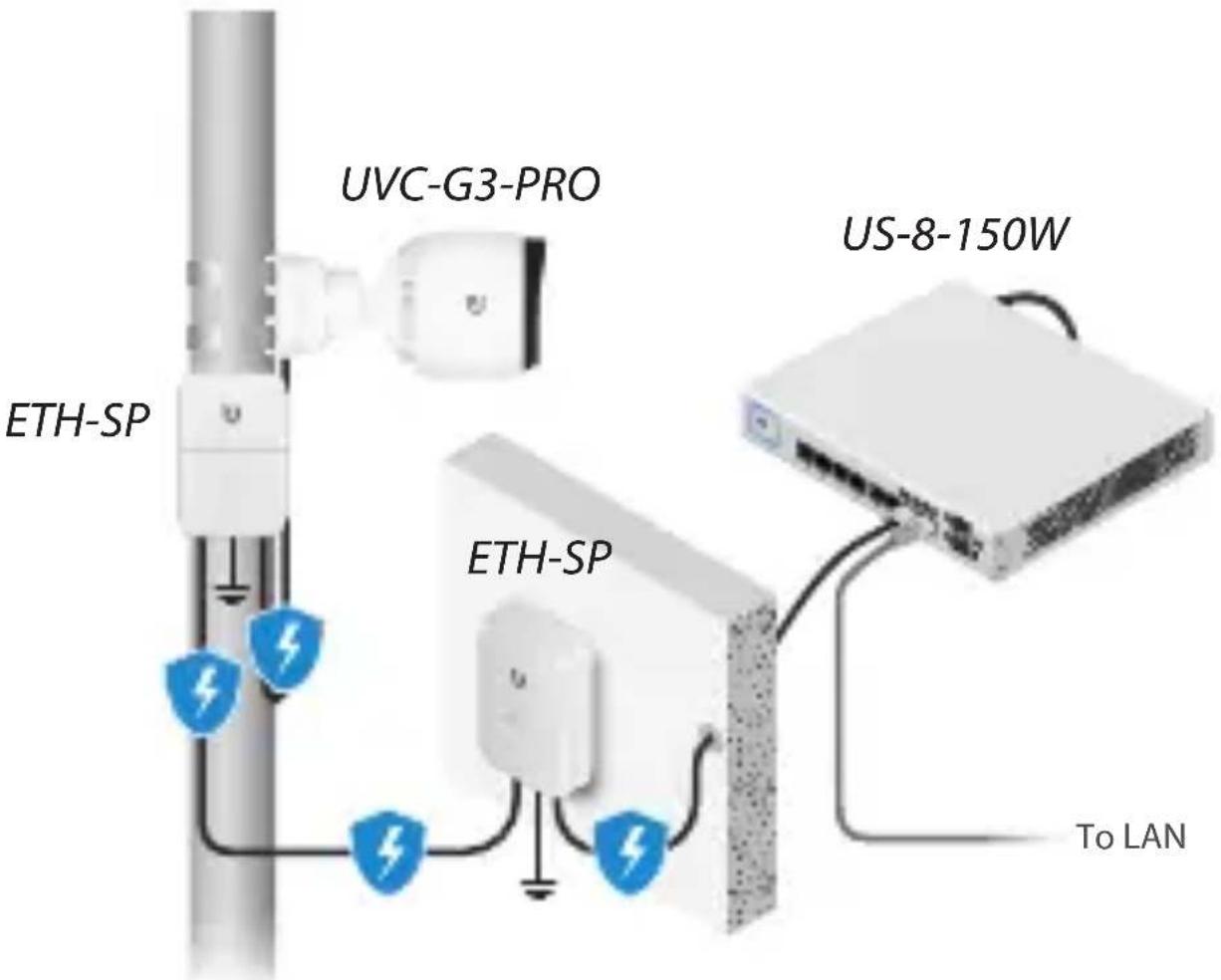
Diagram Showing Use of Ethernet Surge Protectors
TERMS OF USE: All Ethernet cabling runs must use CAT5 (or above). Shielded Ethernet cable and earth grounding must be used for outdoor installations as conditions of product warranty. TOUGHCable™ is designed for outdoor installations. It is the professional installer's responsibility to follow local country regulations.
Hardware Overview

Ethernet 10/100 RJ45 port connects to an 802.3af/802.3at PoE switch for PoE power and data.
Reset Button To reset to factory defaults, press and hold the Reset button for more than 10 seconds while the camera is powered on.
Before You Begin
Remove the sticker from the bottom of the Mounting Base.
Installation Overview
To install the camera, please follow the instructions of the following sections in this order:
- Hardware Installation
- Connecting Power over Ethernet
- UniFi Video
- Adjusting the Camera View
Hardware Installation
The camera can be mounted on a wall, ceiling, or pole. Follow the appropriate steps for your installation:
Wall/Ceiling Mount
- Remove the Mounting Base from the camera by turning the Tilt/Mount Ring counterclockwise.

- Mark the mounting holes on the wall or ceiling.
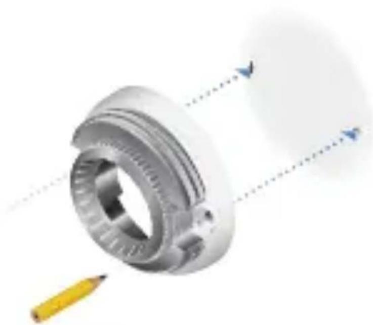

Note: If you are running the cable along the wall or ceiling, position the Cable Slot towards the direction you want the cabling to run. For outdoor installations, position the Cable Slot downward.
- Use a 7 mm ( 1/4 ) drill bit to drill the mounting holes in the wall or ceiling.

Note: If you are running the Ethernet cable through the wall, cut a hole centered between the mounting holes that is large enough to feed the cable through.
- Insert a Screw Anchor into each mounting hole.

- If you are feeding the Ethernet cable through the wall or ceiling, do so now and feed it through the Mounting Base.

If not, feed the Ethernet cable through the Mounting Base and place the cable in the Cable Slot.


IMPORTANT: If you are installing your camera outdoors, create a drip loop for the cable below the camera to prevent water ingress.
- Fasten the Mounting Base to the wall or ceiling using two Self-Tapping Screws.

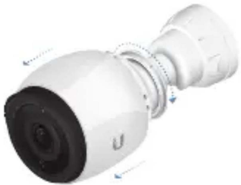
- Remove the camera from the Adjustable Base by turning the Camera Ring in the direction shown.
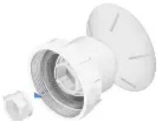
- Remove the Cable Gland from the Adjustable Base.
- Feed the Ethernet cable through the Cable Gland and Adjustable Base. Seal the Cable Gland in place by firmly pressing around its edges. Then connect the cable to the Ethernet Port on the camera.


IMPORTANT: For proper weather sealing, the Cable Gland must fit securely within the Adjustable Base when the camera is mounted. Ensure that the Cable Gland is securely seated during installation and cable routing.
- Connect the camera back to the Adjustable Base by turning the Camera Ring in the direction shown.

- Orient the camera to the desired position while connecting the Adjustable Base to the Mounting Base.

Note: You will fine-tune and then lock the positioning after you check the camera view in the UniFi Video software.

- Proceed to the Connecting Power over Ethernet section.
Pole Mount
To mount the camera on a pole, two metal straps are required (not included).
- Feed the metal straps through the slots on the Pole Mount Bracket.

- Wrap a metal strap around the pole and tighten it by turning the screw clockwise. Repeat for the second strap.

- Remove the Mounting Base from the camera by turning the Tilt/Mount Ring counterclockwise.

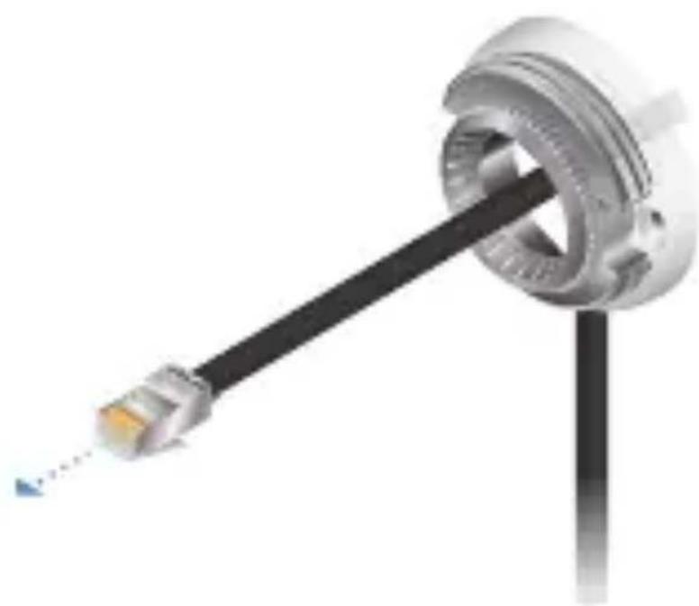
- Feed the Ethernet cable through the Mounting Base.
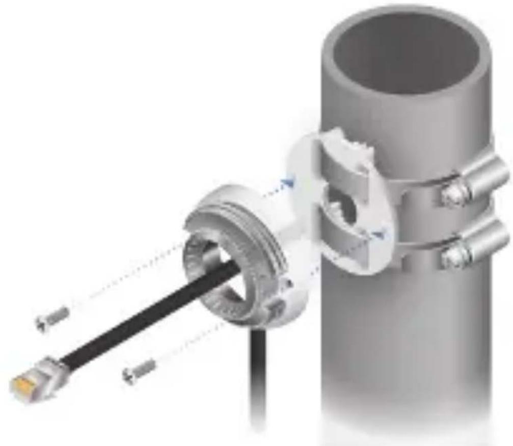
- Fasten the Mounting Base to the Pole Mount Bracket using two Machine Screws.
- Remove the camera from the Adjustable Base by turning the Camera Ring in the direction shown.

- Remove the Cable Gland from the Adjustable Base.
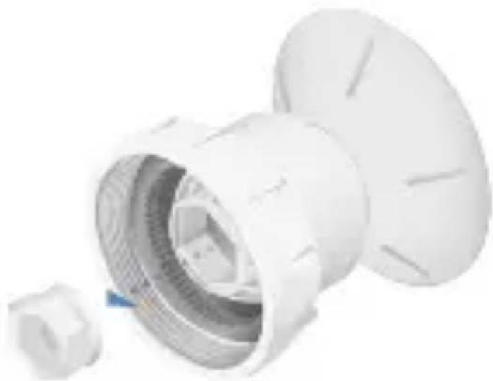
- Feed the Ethernet cable through the Cable Gland and Adjustable Base. Seal the Cable Gland in place by firmly pressing around its edges. Then connect the cable to the Ethernet Port on the camera.


IMPORTANT: For proper weather sealing, the Cable Gland must fit securely within the Adjustable Base when the camera is mounted. Ensure that the Cable Gland is securely seated during installation and cable routing.
- Connect the camera back to the Adjustable Base by turning the Camera Ring in the direction shown.

- Orient the camera to the desired position while connecting the Adjustable Base to the Mounting Base.

Note: Fine-tune and then lock the positioning after you check the camera view in the UniFi Video software.

Connecting Power over Ethernet
The camera features auto-sensing
802.3af/802.3at PoE and can be powered by any 802.3af/802.3at PoE compliant switch, such as a UniFi PoE Switch.
Connect the Ethernet cable from the camera directly to a PoE port on the switch.


640-00316-06
UniFi Video
Ensure that you are running UniFi Video software version 3.9 or newer. The latest version of the UniFi Video software is available at www.ubnt.com/download/unifivideo
The UniFi Video auto-management feature should automatically detect your new camera(s). To manage the camera:
- Click the Unmanaged tab.
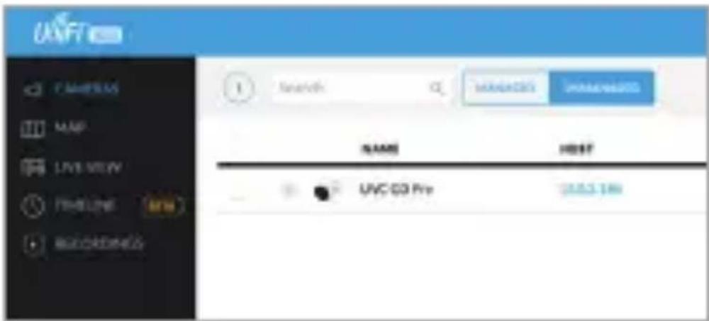
- Select the camera row.

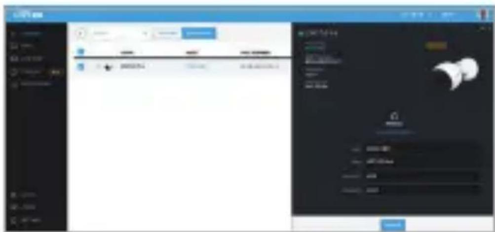
- The Camera Details window will appear on the right side of the screen. Enter ubnt in the Username and Password fields and click Manage.
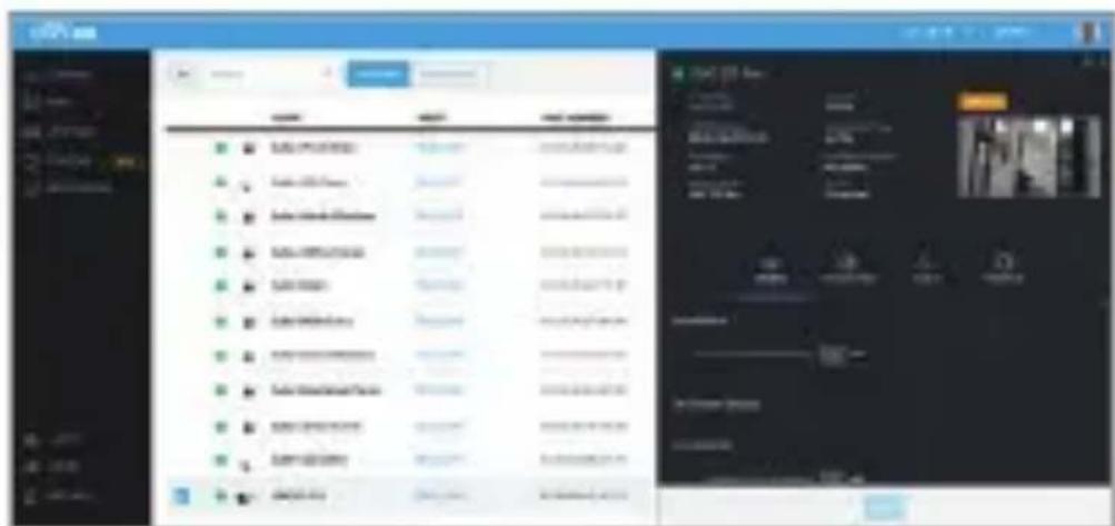
- UniFi Video will automatically update the camera's firmware (this may take up to five minutes). Then the camera will appear in the Managed cameras list. Check the camera view and proceed to the Adjusting the Camera View section.
UniFi Video App

The UniFi Video app is available from the App Store (iOS) or Google Play™ (Android).

For details on using the UniFi Video software, refer to the User Guide at:
www.ubnt.com/download/unifivideo
Adjusting the Camera View
-
Fine-tune the positioning as you check the camera preview in the software.
-
Ensure that the arrow side of the included Tightening Tool faces the camera. Then insert the Tightening Tool between the camera and Adjustable Base.

- Fit the Tightening Tool to the camera.

- Turn the Tightening Tool to tighten the Camera Ring.
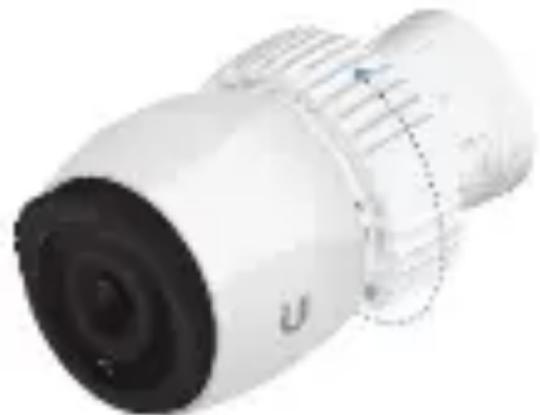
- Move the Tightening Tool to fit the Tilt/Mount Ring.

- Secure the Tilt/Mount Ring to lock the positioning and complete installation.

Specifications
| UVC-G3-PRO | |
| Dimensions(Without Mounting Plate) | ∅ 86 x 153 mm (∅ 3.39 x 6.02") |
| Weight(Without Mounting Plate) | 700 g (1.54 lb) |
| Enclosure UV Stabilized Polycarbonate and Die-Cast Aluminum | |
| Networking Interface | (1) 10/100 Ethernet Port |
| Sensor Sony IMX290, 1/2.8" | |
| Lens 3-9 mm, f/1.2-f/2.1 Powered Zoom Lens | |
| Field of ViewWideTele | 108° (H), 58° (V), 125° (D)37° (H), 20° (V), 43° (D) |
| Night Mode IR LEDs with Mechanical IR Cut Filter | |
| Video Compression H.264 | |
| Resolution 1080p Full HD (1920 x 1080) | |
| Maximum Frame Rate | 30 FPS |
| Image Settings Flip, Brightness, Contrast,WDR, Hue, Infrared,Sharpness, Saturation,Denoise, 50/60 Hz FlickerReduction | |
| ManagementInterfaceManaged ModeStandalone Mode | UniFi Video v3.9 or NewerCamera Integrated Web UI |
| Microphone Yes | |
| Max. PowerConsumption | 12.5W |
| Power Method IEEE 802.3af/802.3at PoE | |
| Power Supply 802.3af/802.3at PoE Switch | |
| Buttons Factory Reset Button | |
| Mounting Wall/Ceiling (Kits Included)Pole (Bracket Included) | |
| OperatingTemperature | -20 to 50°C-4 to 122°F |
| Operating Humidity 0 to 90% Noncondensing | |
Safety Notices
- Read, follow, and keep these instructions.
- Heed all warnings.
- Only use attachments/accessories specified by the manufacturer.

WARNING: This product may become hot during operation. Exercise caution when handling.

WARNING: Do not use this product in a location that can be submerged by water.

WARNING: Avoid using this product during an electrical storm. There may be a remote risk of electric shock from lightning.
Electrical Safety Information
-
Compliance is required with respect to voltage, frequency, and current requirements indicated on the manufacturer's label. Connection to a different power source than those specified may result in improper operation, damage to the equipment or pose a fire hazard if the limitations are not followed.
-
There are no operator serviceable parts inside this equipment. Service should be provided only by a qualified service technician.
Limited Warranty
UBIQUITI NETWORKS, Inc ("UBIQUITI NETWORKS") warrants that the product(s) furnished hereunder (the "Product(s)") shall be free from defects in material and workmanship for a period of one (1) year from the date of shipment by UBIQUITI NETWORKS under normal use and operation. UBIQUITI NETWORKS' sole and exclusive obligation and liability under the foregoing warranty shall be for UBIQUITI NETWORKS, at its discretion, to repair or replace any Product that fails to conform to the above warranty during the above warranty period. The expense of removal and reinstallation of any Product is not included in this warranty. The warranty period of any repaired or replaced Product shall not extend beyond its original term.
Warranty Conditions
The above warranty does not apply if the Product:
(I) has been modified and/or altered, or an addition made thereto, except by Ubiquiti Networks, or Ubiquiti Networks' authorized representatives, or as approved by Ubiquiti Networks in writing;
(II) has been painted, rebranded or physically modified in any way;
(III) has been damaged due to errors or defects in cabling;
(IV) has been subjected to misuse, abuse, negligence, abnormal physical, electromagnetic or electrical stress, including lightning strikes, or accident;
(V) has been damaged or impaired as a result of using third party firmware;
(VI) has no original Ubiquiti MAC label, or is missing any other original Ubiquiti label(s); or
(VII) has not been received by Ubiquiti within 30 days of issuance of the RMA.
In addition, the above warranty shall apply only if: the product has been properly installed and used at all times in accordance, and in all material respects, with the applicable Product documentation; all Ethernet cabling runs use CAT5 (or above), and for outdoor installations, shielded Ethernet cabling is used, and for indoor installations, indoor cabling requirements are followed.
Returns
No Products will be accepted for replacement or repair without obtaining a Return Materials Authorization (RMA) number from UBIQUITI NETWORKS during the warranty period, and the Products being received at UBIQUITI NETWORKS' facility freight prepaid in accordance with the RMA process of UBIQUITI NETWORKS. Products returned without an RMA number will not be processed and will be returned freight collect or subject to disposal. Information on the RMA process and obtaining an RMA number can be found at: www.ubnt.com/support/warranty
Disclaimer
EXCEPT FOR ANY EXPRESS WARRANTIES PROVIDED HEREIN, UBIQUITI NETWORKS, ITS AFFILIATES, AND ITS AND THEIR THIRD PARTY DATA, SERVICE, SOFTWARE AND HARDWARE PROVIDERS HEREBY DISCLAIM AND MAKE NO OTHER REPRESENTATION OR WARRANTY OF ANY KIND, EXPRESS, IMPLIED OR STATUTORY, INCLUDING, BUT NOT LIMITED TO, REPRESENTATIONS, GUARANTEES, OR WARRANTIES OF MERCHANTABILITY, ACCURACY, QUALITY OF SERVICE OR RESULTS, AVAILABILITY, SATISFACTORY QUALITY, LACK OF VIRUSES, QUIET ENJOYMENT, FITNESS FOR A PARTICULAR PURPOSE AND NON-INFRINGEMENT AND ANY WARRANTIES ARISING FROM ANY COURSE OF DEALING, USAGE OR TRADE PRACTICE IN CONNECTION WITH SUCH PRODUCTS
AND SERVICES. BUYER ACKNOWLEDGES THAT NEITHER UBIQUITI NETWORKS NOR ITS THIRD PARTY PROVIDERS CONTROL BUYER'S EQUIPMENT OR THE TRANSFER OF DATA OVER COMMUNICATIONS FACILITIES, INCLUDING THE INTERNET, AND THAT THE PRODUCTS AND SERVICES MAY BE SUBJECT TO LIMITATIONS, INTERRUPTIONS, DELAYS, CANCELLATIONS AND OTHER PROBLEMS INHERENT IN THE USE OF COMMUNICATIONS FACILITIES. UBIQUITI NETWORKS, ITS AFFILIATES AND ITS AND THEIR THIRD PARTY PROVIDERS ARE NOT RESPONSIBLE FOR ANY INTERRUPTIONS, DELAYS, CANCELLATIONS, DELIVERY FAILURES, DATA LOSS, CONTENT CORRUPTION, PACKET LOSS, OR OTHER DAMAGE RESULTING FROM ANY OF THE FOREGOING. In addition, UBIQUITI NETWORKS does not warrant that the operation of the Products will be error-free or that operation will be uninterrupted. In no event shall UBIQUITI NETWORKS be responsible for damages or claims of any nature or description relating to system performance, including coverage, buyer's selection of products (including the Products) for buyer's application and/or failure of products (including the Products) to meet government or regulatory requirements.
Limitation of Liability
EXCEPT TO THE EXTENT PROHIBITED BY LOCAL LAW, IN NO EVENT WILL UBIQUITI OR ITS SUBSIDIARIES, AFFILIATES OR SUPPLIERS BE LIABLE FOR DIRECT, SPECIAL, INCIDENTAL, CONSEQUENTIAL OR OTHER DAMAGES (INCLUDING LOST PROFIT, LOST DATA, OR DOWNTIME COSTS), ARISING OUT OF THE USE, INABILITY TO USE, OR THE RESULTS OF USE OF THE PRODUCT, WHETHER BASED IN WARRANTY, CONTRACT, TORT OR OTHER LEGAL THEORY, AND WHETHER OR NOT ADVISED OF THE POSSIBILITY OF SUCH DAMAGES.
Note
Some countries, states and provinces do not allow exclusions of implied warranties or conditions, so the above exclusion may not apply to you. You may have other rights that vary from country to country, state to state, or province to province. Some countries, states and provinces do not allow the exclusion or limitation of liability for incidental or consequential damages, so the above limitation may not apply to you. EXCEPT TO THE EXTENT ALLOWED BY LOCAL LAW, THESE WARRANTY TERMS DO NOT EXCLUDE, RESTRICT OR MODIFY, AND ARE IN ADDITION TO, THE MANDATORY STATUTORY RIGHTS APPLICABLE TO THE LICENSE OF ANY SOFTWARE (EMBEDDED IN THE PRODUCT) TO YOU. The United Nations Convention on Contracts for the International Sale of Goods shall not apply to any transactions regarding the sale of the Products.
Compliance
FCC
Changes or modifications not expressly approved by the party responsible for compliance could void the user's authority to operate the equipment.
This device complies with part 15 of the FCC Rules. Operation is subject to the following two conditions:
- This device may not cause harmful interference, and
- This device must accept any interference received, including interference that may cause undesired operation.
This equipment has been tested and found to comply with the limits for a Class A digital device, pursuant to part 15 of the FCC Rules. These limits are designed to provide
reasonable protection against harmful interference when the equipment is operated in a commercial environment. This equipment generates, uses, and can radiate radio frequency energy and, if not installed and used in accordance with the instruction manual, may cause harmful interference to radio communications. Operation of this equipment in a residential area is likely to cause harmful interference in which case the user will be required to correct the interference at his own expense.
ISED Canada
CAN ICES-3(A)/NMB-3(A)
This Class A digital apparatus complies with Canadian CAN ICES-003.
CAN ICES-3(A)/NMB-3(A)
CE marking on this product represents the product is in compliance with all directives that are applicable to it.

Australia and New Zealand

Warning: This is a Class A product. In a domestic environment this product may cause radio
interference in which case the user may be required to take adequate measures.
RoHS/WEEE Compliance Statement

English
European Directive 2012/19/EU requires that the equipment bearing this symbol on the product and/or its packaging must not be disposed of with unsorted municipal waste.
The symbol indicates that this product should be disposed of separately from regular household waste streams. It is your responsibility to dispose of this and other electric and electronic equipment via designated collection facilities appointed by the government or local authorities. Correct disposal and recycling will help prevent potential negative consequences to the environment and human health. For more detailed information about the disposal of your old equipment, please contact your local authorities, waste disposal service, or the shop where you purchased the product.
Deutsch
Declaration of Conformity
www.ubnt.com/compliance
English Hereby, UBIQUITI NETWORKS, declares that this UVC-G3-PRO device, is in compliance with the essential requirements and other relevant provisions of Directives 2014/30/EU, 2014/35/EU. The full text of the EU declaration of conformity is available at the following internet address: www.ubnt.com/compliance
www.ubnt.com/compliance
www.ubnt.com/compliance
Online Resources
Website www.ubnt.com
Support help.ubnt.com
Community community.ubnt.com
Downloads downloads.ubnt.com

UBIQUITI
NEW ORES
Ubiquiti Networks, Inc.
685 Third Avenue, 27th Floor
New York, NY 10017
USA
©2017 Ubiquiti Networks, Inc. All rights reserved. Ubiquiti, Ubiquiti Networks, the Ubiquiti U logo, the Ubiquiti beam logo, UniFi, and UniFi Video are trademarks or registered trademarks of Ubiquiti Networks, Inc. in the United States and in other countries. Apple and the Apple logo are trademarks of Apple Inc., registered in the U.S. and other countries. App Store is a service mark of Apple Inc. Android, Google, Google Play, the Google Play logo and other marks are trademarks of Google Inc. All other trademarks are the property of their respective owners.


- UNIFI VIDEO®
- INTRODUCTION
- INSTALLATION REQUIREMENTS
- BEFORE YOU BEGIN
- INSTALLATION OVERVIEW
- HARDWARE INSTALLATION
- WALL/CEILING MOUNT
- POLE MOUNT
- CONNECTING POWER OVER ETHERNET
- UNIFI VIDEO
- UNIFI VIDEO APP
- ADJUSTING THE CAMERA VIEW
- SPECIFICATIONS
- SAFETY NOTICES
- ELECTRICAL SAFETY INFORMATION
- LIMITED WARRANTY
- WARRANTY CONDITIONS
- RETURNS
- DISCLAIMER
- LIMITATION OF LIABILITY
- NOTE
- COMPLIANCE
- FCC
- ISED CANADA
- CAN ICES-3(A)/NMB-3(A)
- AUSTRALIA AND NEW ZEALAND
- ROHS/WEEE COMPLIANCE STATEMENT
- ENGLISH
- DEUTSCH
- DECLARATION OF CONFORMITY
- WWW.UBNT.COM/COMPLIANCE
- ONLINE RESOURCES
Brand : Ubiquiti Networks
Model : G3-PRO
Category : Security Camera