UVC-G3-AF-5 - Security Camera Ubiquiti Networks - Free user manual and instructions
Find the device manual for free UVC-G3-AF-5 Ubiquiti Networks in PDF.

User questions about UVC-G3-AF-5 Ubiquiti Networks
0 question about this device. Answer the ones you know or ask your own.
Ask a new question about this device
Download the instructions for your Security Camera in PDF format for free! Find your manual UVC-G3-AF-5 - Ubiquiti Networks and take your electronic device back in hand. On this page are published all the documents necessary for the use of your device. UVC-G3-AF-5 by Ubiquiti Networks.
USER MANUAL UVC-G3-AF-5 Ubiquiti Networks
natural_image
Exterior view of a UBIQUITI NETWORKS device setup with security camera and server unit (no signage)UniFi®
VIDEO
IP Camera/NVR
Management System
Software Release: 3.9
USER GUIDE
Table of Contents
Chapter 1: Installation....1
Overview....1
Supported Products....1
System Requirements ....1
Hardware Installation....1
Software Installation....1
UniFi Video Setup 2
Launching UniFi Video....4
Non-Cloud UniFi Video Setup....4
Enabling Cloud Access from Existing Installations ....6
Chapter 2: Cameras....7
Camera Details Window 8
Chapter 3: Map....13
Defining a Map....13
Chapter 4: Live View....15
Create a New View ....15
Edit a View ....16
Chapter 5: Timeline....17
Selecting a Clip for Playback....17
Playback 18
Chapter 6: Recordings....21
Viewing Recordings 22
Chapter 7: Alerts ...... 23
Alerts Home Page 23
Chapter 8: Users....25
User Details 25
Chapter 9: Settings....29
NVR Settings 30
Appendix A: Mobile App 33
UniFi Video App for iOS....33
UniFi Video App for Android 39
Appendix B: Standalone Mode 45
Using Standalone Mode 45
Configuring the Camera ....48
Standalone Mode from UniFi Video 48
Appendix C: Contact Information....51
Ubiquiti Networks Support ....51
Chapter 1: Installation
Overview
UniFi Video® is a powerful and flexible, integrated IP video management surveillance system designed to work with Ubiquiti's UniFi Video Camera product line. UniFi Video has an intuitive, configurable, and feature-packed user interface with advanced features such as motion detection, auto-discovery, user-level security, storage management, reporting, and mobile device support.
The UniFi Video software comes pre-installed on the UniFi NVR and requires no additional software installation. This chapter provides instructions for users who are not using the UniFi NVR and wish to install the UniFi Video software on a computer or other hardware platform that meets the system requirements listed below.
Supported Products
The following models of the UniFi® Video Camera are supported by v3.9:
• UniFi Video Camera G3 (UVC-G3, UVC-G3-AF)
• UniFi Video Camera G3 Dome (UVC-G3-DOME)
• UniFi Video Camera G3 Micro (UVC-G3-MICRO)
• UniFi Video Camera G3 Pro (UVC-G3-PRO)
• UniFi Video Camera (UVC)
• UniFi Video Camera Pro (UVC-Pro)
• UniFi Video Camera Dome (UVC-Dome)
• UniFi Video Camera Micro (UVC-Micro)

Note: UniFi Video 3.2.0 and above does not support airCams.
System Requirements
- 64-bit Debian 7.0 (or above), Ubuntu v14.04 or v16.04, or Microsoft Windows 8/7 system with an Intel or compatible 1.86 GHz (or above) processor with a minimum of 2GB RAM
• Mobile: iOS or Android
• Java Runtime Environment 1.7 or newer
• Web Browser: Google Chrome
Hardware Installation
Ensure that each camera on your network is running the latest version of the firmware. The latest firmware (and other UniFi Video downloads) can be found online at: www.ubnt.com/download
Follow the directions in the Quick Start Guide that accompanied your UniFi Video Camera to install your cameras.
Software Installation
Download the latest version of the UniFi Video software at: www.ubnt.com/download
Then follow the instructions for your system.
Windows Installation
To install the software on Windows:
- Run the downloaded UniFi Video installer file as Administrator. You may be asked to allow the program to make changes to the computer you're installing it on. If so, click Yes.
- When the Ubiquiti UniFi Video Setup wizard starts, click Next to continue the installation.

text_image
Ubiquiti UniFi Video v3.9.0 Welcome to the Ubiquiti UniFi Video v3.9.0 Setup Wizard This wizard will guide you through the installation of Ubiquiti UniFi video v3.9.0. It is recommended that you close all other applications before starting Setup. This will make it possible to update relevant system files without having to reboot your computer. Click Next to continue. Please note: arCam products are not supported in this version! Next > Cancel- Click I Agree to accept the license agreement and continue with setup wizard.

text_image
Ubiquiti UniFi Video v3.9.0 License Agreement Please review the license terms before installing Ubiquiti UniFi Video v3.9.0. Press Page Down to see the rest of the agreement. Ubiquiti® End User License Agreement Ubiquiti NETWORKS, INC. ("UNNT") LICENSERS THIS SOFTWARE TO YOU (My/Youor "LICENSEE") SUBJECT TO THE TERMS CONTAINED IN THIS END USER LICENSE
AGREEMENT ("AGREEMENT"). READ THE TERMS AND CONDITIONS OF THIS AGREEMENT CARFULLY BEFORE INSTALLING, COPYING AND/OR USING THIS SOFTWARE (ALONG WITH ANY UPGRADES, UPDATES, BUG FIXES OR MODIFIED VERSIONS THERATO, COLLECTIVELY, THE "SOFTWARE") AND THE ACCOMpanyING DOCUMENTATION AND DOCUMENTATIONS MEANS WRITTEN INFORMATION (WHEHTER CONTAINED IN USER OR TECHNICAL MANUALS, TRAINING MATERIALS, If you accept the terms of the agreement, click I Agree to continue. You must accept the agreement to install Ubiquiti UniFi Video v3.9.0. Ubiquiti Networks, Inc. < Back 1 Agree Cancel- The UniFi Video Setup wizard will install files on your system. When it is finished, click Next.

text_image
Ubiquiti UniFi Video v8.9.0 Setup Installation Complete Setup was completed successfully. Completed Show details Ubiquiti Networks, Inc. < Back Next > CancelChapter 1: Installation UniFi Video User Guide
- If your computer doesn't have Java 1.7 or 1.8 software installed, you will be prompted to install it. Click Install to continue.

text_image
Java Setup - Welcome Welcome to Java Java provides safe and secure access to the world of amazing Java content. From business solutions to helpful utilities and entertainment. Java makes your internet experience come to life. Note: No personal information is gathered as part of our install process. Click here for more information on what we do collect. Click install to accept the license agreement and install Java save Change destination folder Cancel Install>- Click ClosFinish the installation. This will start the UniFi Video service.
Linux Installation
To install the software on linux, enter the following:
sudo dpkg -i
where installation_file is the file you downloaded from www.ubnt.com/download
Mobile Installation
For detailed information on installing and using the mobile app, refer to "Mobile App" on page 33.
UniFi Video Setup
Follow these instructions to set up the UniFi Video software for cloud access:
-
Open the Chrome browser application on any computer on the same network as the installed software.
-
Enter https://video.ubnt.com in your browser's address field. Press Enter (PC) or Return (Mac).
-
Enter the Username and Password for your Ubiquiti account. Click Sign In.

Note: If you do not have a Ubiquiti account, create one as follows:
-
Click Register.
-
Enter the requested information. Click Register.
-
A verification e-mail will be sent to the e-mail account you specified. Open the e-mail and click the link to verify your account.

text_image
UBFI URSOLUTI One account the flight service Through or continue Password: Sign in: Password prompt- Click Get Started to begin setup of your NVR.

text_image
Setup your NVR Get Started- The setup wizard will search for the NVR on your network.

text_image
Locate Your NVR Sailing Passes for NVR...- If your NVR cannot be found, the wizard displays "Unable to Locate NVR". Verify that the NVR is connected to your network and click Rescan to try again.

text_image
UNIFI e83 Unable to Locate NVR Please make any your NVR is connected to your local network. Rescue- The NVR Discovered window will appear, listing any NVRs that were discovered. Select your NVR and click Continue.

text_image
UniFi NVR NVR Discovered Selected on NVR Display Format UniFi-NVR Multi-Display Format- The Setup NVR window will appear:
a. Enter a name for the NVR.
b. Specify your time zone.
c. Select I agree to the Terms of Service (click Terms of Service to view the Terms of Service).
d. Click Next.

text_image
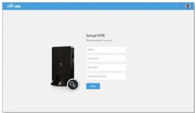
UNIFI Setup NVR Configure your NVR Name Your NVR IUTC-08:00 Pacific Time (US & C) Gateway to the Terminal Service New Add to new server- Create the local admin account by entering a Name, Username, and Password (enter twice to confirm). This information will be used to log in and access the UniFi Video Controller system. Click Next.
text_image
Setup NVR Setup local within account. Name Username Password Password Password New- The Setup Cameras window will appear, displaying a randomly generated password (you can change this password later in the Settings section). Click Continue.

text_image
Setup Cameras Camera Recovery Password Any camera you manage will use this password. Start Menu CONTINUE- When the firmware update is complete, "Setup Complete" will be displayed. Click Go to Cameras:
Launching UniFi Video
After you have set up UniFi Video on your NVR, launch UniFi Video from the cloud as follows:
- Open the Chrome browser application on a computer with an Internet connection.
- Enter https://video.ubnt.com in your browser's address field. Press Enter (PC) or Return (Mac).
- Enter the Username and Password for your Ubiquiti account. Click Sign In.
- UniFi Video will connect to your NVR and open.

Note: You can also launch UniFi Video from a computer on the same network as the NVR:
- Open the Chrome browser application on a computer on the same network as the NVR.
- Enter https://
- Enter the Username and Password for your admin account on the NVR. Click Sign In.
- The UniFi Video application will open.
Proceed to the appropriate chapter for information on using the UniFi Video Management software:
- "Cameras" on page 7
• "Map" on page 13
• "Live View" on page 15
• "Timeline" on page 17
• "Recordings" on page 21 - "Alerts" on page 23
• "Users" on page 25
• "Settings" on page 29
Non-Cloud UniFi Video Setup
This section describes how to launch and set up UniFi Video using the software installed in "Software Installation" on page 1.
Windows Launch
Launch includes two steps:
- Start the UniFi Video service. If you selected Start UniFi Video after installation when you installed the software, the UniFi Video service will be started automatically. If you didn't select the option to start the UniFi Video service automatically, you can start it using one of the following two methods:
- Start Menu
a. Click the Start menu and select All Programs from the popup menu.
b. Scroll down to Ubiquiti UniFi Video and click the folder name once to expand its contents.
c. Select Ubiquiti UniFi Video. This will launch the UniFi Video tray icon in the bottom right corner of the Windows taskbar.

text_image
Ubiquiti UniFi Video UniFi Video Uninstall UniFi Video Back Search programs and filesUniFi Video Tray Icon

- Desktop Icon
a. Double-click the icon shown below to start the UniFi Video service.

b. The UniFi Video tray icon will appear in the bottom right corner of the Windows taskbar.
UniFi Video Tray Icon

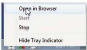
- Click the UniFi Video tray icon and select Open in Browser from the pop-up menu.
text_image
Open in Browser Start Stop Hide Tray IndicatorThe UniFi Video software will open in your browser. The first time you use the software, set up the NVR as detailed in "Windows UniFi Video Setup" on page 5.
Windows UniFi Video Setup
- If you receive a security warning, click Advanced, and then click Proceed to
.

text_image
Your connection is not private Attorneys might be trying to select your information from 10.0.3.197 (for example, passwords, messages, or credit cards). http://www.10.0.3.197, e-mail:10.0.3.197 □ Automatically request details of possible security incidents to Google. Email:public Home advanced Next to email This server could not prove that it is 10.0.3.197. Its security certificate is not trusted by your computer's operating system. This may be caused by a misconfiguration or an attacker interesting your connection. Present to 10.0.3.197 as follows- The Setup NVR window will appear:
a. Enter a name for the NVR.
b. Specify your time zone.
c. Select I agree to the Terms of Service (click Terms of Service to view the Terms of Service).
d. Click Next.

text_image
UNIFI Setup NVR Configure your NVR. Name: Your NVR UTC 08:00 Pacific Time (US&C) Agree to the Turnout of Service Next MORDER COPY- Create an Admin account by entering a Name, Username, and Password (enter twice to confirm). This information will be used to log in and access the UniFi Video Controller system. Click Next.

text_image
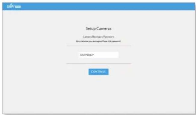
URFI Setup NVR Setup local admin network Name Username Password Password Password Next- The Setup Cameras window will appear. Enter a password (twice to confirm) to be used to manage your cameras.
text_image
Setup Cameras Camera Recovery Password Any cameras you manage will use this password. SUPHsUpDV CONTINUE- When the firmware update is complete, "Setup Complete" is displayed. Click Go to Cameras.
Proceed to the appropriate chapter for information on using the UniFi Video Management software:
- "Cameras" on page 7
- "Map" on page 13
• "Live View" on page 15
• "Timeline" on page 17
• "Recordings" on page 21
• "Alerts" on page 23 - "Users" on page 25
- "Settings" on page 29
Enabling Cloud Access from Existing Installations
If you have upgraded to UniFi Video version 3.8 from an older version, follow these instructions to enable cloud access to your UniFi Video Management system:
- Launch the UniFi Video Management software, as described in "Launching UniFi Video" on page 4.
- Click Settings to open the Settings page.
- Click Connect to My Ubiquiti Account.

Note: If you do not have a Ubiquiti account, you must create one before continuing. Create a new Ubiquiti account as follows:
- Go to https://video.ubnt.com
- Click Register.
- Enter the requested information. Click Register.
-
A verification e-mail will be sent to the e-mail account you specified in the previous step. Open the e-mail and click the link to verify your account.
-
Enter your Username and Password of your Ubiquiti account to connect the account to the NVR.
- You will now be able to access your UniFi Video Management system from https://video.ubnt.com

text_image
UniFi CAMERAS MAP LIVE VIEW TIMELINE RECORDINGS 12 Search MANAGED UNMANAGED NAME HOST MAC ADDRESS LAST RECORDING LINK STATE QA G3 Micro Android 192.168.10.162 F0: RF:CC:CC:CC:BL n/a -59 dBm LIVE FEED QA G3 Micro iOS 192.168.10.171 F0: RF:CC:CC:CC:RF n/a -63 dBm LIVE FEED QA UVC Pro 192.168.10.108 DC: RF:CB:BC:BA:AZ n/a 100 Mbps LIVE FEED QA G3 Micro1 192.168.10.119 04:18:DC:AD:BA:AC n/a -63 dBm LIVE FEED QA G3 Micro2 192.168.10.123 04:18:DC:AD:BA:RE n/a -73 dBm LIVE FEED QA UVC Dome 192.168.10.213 04:18:DC:AD:AE:RE n/a 100 Mbps LIVE FEED QA UVC G3 AF1 192.168.10.203 F0: RF:CC:CC:FC:FC n/a 100 Mbps LIVE FEED QA UVC G3 AF2 192.168.10.147 F0: RF:CC:CC:FC:FC n/a 100 Mbps LIVE FEED QA UVC G3 Dome 192.168.10.91 04:18:DC:AD:BA:BE n/a 100 Mbps LIVE FEED QA UVC G3 Micro2 192.168.10.140 04:18:DC:AD:BA:BE n/a -58 dBm LIVE FEED QA UVC Micro1 192.168.10.104 64:28:E7:E4:E2:E3 n/a -56 dBm LIVE FEED QA UVC Micro5 192.168.10.167 64:28:E7:E4:E2:E3 n/a -36 dBm LIVE FEEDChapter 2: Cameras
On the Cameras page, you have the option to view all cameras (default), a selected group of cameras, or a single camera, depending on your search criteria. The Search option will narrow down the list of cameras displayed as you type characters into the Search text field, eliminating the ones that don't match your search criteria. The searchable columns are Name, Host, and MAC Address.
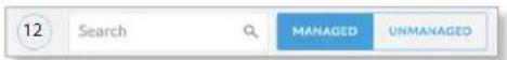
Each camera will be categorized as Managed or Unmanaged and the number in the upper left corner indicates how many cameras you have per category. In this example, there are 12 Managed cameras.
Cameras listed under the Managed tab have been added to the UniFi Video management system. Cameras listed under the Unmanaged tab have not been configured or added to the UniFi Video management system yet, or have been unmanaged.
To change the status of a camera from Unmanaged to Managed, follow these steps:
- Click Unmanaged to see a list of unmanaged cameras.
- Click a camera to view its details. Refer to "Configuration" on page 12.
- Enter the username and password for the selected camera and click Manage.
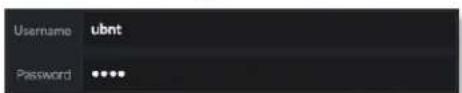
text_image
Username ubnt Password ****Ubiquiti Networks, Inc.
Once you've finished adding the unmanaged cameras, click Managed to return to the Managed cameras view.
| NAME | HOST | MAC ADDRESS | LAST RECORDING | LINK STATE |
For each camera, the Managed camera view lists the Name, Host (address), MAC Address, Last Recording, and Link State. Click a column heading to sort the list by that column; click again to reverse the sort order.
Name Displays the local device name and a thumbnail image of the camera.
Host Displays the local host IP address assigned to each specific camera.
MAC Address Displays the MAC Address of the camera. Each camera has its own unique hardware address.
Last Recording Displays how long it has been since a camera recorded something based on its recording mode. Refer to "Recording" on page 11.
Link State Displays the following information for the currently selected camera:
- Connection type:
- Wired or Wireless

Green icon: Camera is connected Gray icon: Camera is disconnected
- Connection state: Connected, Disconnected, Rebooting, Unauthenticated
- Connection speed in Mbps (wired cameras only)
- Connection quality in dBm (wireless cameras only)
Live Feed Click LIVE FEED to view a live feed of the selected camera.

natural_image
Interior view of a hallway with ceiling-mounted equipment and wall-mounted screens (no visible text or symbols)Camera Details Window
Click a camera to view the details window and display its IP Address, MAC Address, Model Name, Uptime, Connected Time, Last Motion At, and Status. To select more than one camera, click the checkbox next to each camera. To select a range of cameras, press and hold Shift, and then click the first and last cameras in the range.

Note: To select a camera, do not click the Host column (doing so brings up the camera's standalone web UI, described in "Using Standalone Mode" on page 45).
The Camera Details window also has four clickable tabs: Video, Recording, Stats, and Manage.

text_image
UVC G3 AF1 IP Address: 192 168 10 203 MAC Address: F0.3F.C2.C0.F6FC Firmware: v4.1.8 Model Name: UVC G3 Uptime: 1h 44m 30s Connected Time: 16m 45s Last Recording At: No motion Camera Status: Connected VIDEO RECORDING STATS MANAGE REPORTIP Address Displays the local IP address of the camera.
MAC Address Displays the MAC (Media Access Control) Address of the camera. Each camera has its own unique hardware address.
Firmware Displays the version of the firmware currently installed on the camera.
Model Name Displays the model name of the camera.
Uptime Displays the amount of time that a camera has been running without interruption or since last reboot.
Connected Time Displays the amount of the time the camera has been connected.
Last Recording At Displays the last date and time that a recording took place for the camera you are currently viewing.
Status Displays the current status of the camera. Indicators are Connected, Disconnected, or Rebooting. If Disconnected is displayed, a message summarizing the reason for the disconnection is also displayed. The following table describes these messages in detail:
| Message Detailed Description | |
| Error Conditions | |
| Camera Database Failure | UniFi Video database corruption was detected during a camera firmware upgrade. |
| Unauthorized Access | The camera username and/or password were rejected when attempting to manage a camera. |
| Authentication Failed | The camera and/or the controller failed during their mutual authentication process. |
| Upgrade Failed The | camera firmware upgrade failed. |
| Connection Lost The | controller lost its connection with the camera. |
| Provisioning Failed | The controller failed to provision the camera during the camera management process. |
| Video Settings Failed | The controller failed while applying video settings during the camera management process. |
| Password Sync Failed | The controller failed while updating the camera password. |
| Analytics Settings Failed | The controller failed while applying analytics settings during the camera management settings. |
| Network Status Settings Failed | The controller failed while applying network settings during the camera management settings. |
| Controller Bad Request | The controller sent a bad request to the camera. |
| Connection Timeout | The connection timed out while the controller was trying to send the camera a message. |
| Camera Error An internal camera error was reported back to the controller. | |
| Firmware Not Supported | The controller detected an unsupported firmware installed on a camera it is trying to manage. |
| No Route To Host The | the controller is unable to reach the camera from its IP address. |
| Certificate Mismatch | The controller has detected a certificate mismatch during the authentication process. |
| Informational | |
| Upgrade In Progress | The controller disconnected the camera due to the camera firmware upgrade being initiated. |
| Rebooting The controller disconnected the camera due to the user rebooting the camera from the UniFi Video web application. | |
| Updating Password | The controller has requested a password update to the camera. |
| Camera Umanaged | The controller un-managed the camera. |
| Camera Discovered | The controller discovered a camera. |
| Camera Initialized The controller is initialized and can be managed. | |
Reboot (Functional for administrators only.) Click Reboot to reboot the camera. The camera's status will temporarily change from Connected to Rebooting, and then Disconnected before coming back online as Connected. Rebooting a camera will also reset the Uptime and Connected Time fields in the details window.
Hide Details Click to hide the camera details. Click it again to reveal the camera details.
Exit Camera Detail Click ✗ to close and exit the Camera Details window.
Live Stream Click the image thumbnail in the upper-right corner to display the live stream window of the selected camera.
Live Stream Window

text_image
Entrance to Hall 2016-04-29 16:03:12 Entrance to HallThe Live Stream window above has a menu bar in the upper right corner that allows you to view the camera feed in Full Screen, adjust the Image Settings, take a Snapshot of the live feed, change the Camera Resolution, and adjust the volume controls for audio input and output.
Full Screen Click to view the live stream window in full screen. Press esc on your keyboard to exit full screen mode and return to the window view.
Image Settings Click to view the imaging drop-down menu that allows you to change the live view image settings for each of the following:
- Brightness Adjust the brightness of the live view image by dragging the slider control to the left or right.
- Contrast Adjust the contrast of the live view image by dragging the slider control to the left or right.
- Hue Adjust the hue of the live view image by dragging the slider control to the left or right.
- Saturation Adjust the saturation of the live view image by dragging the slider control to the left or right.
- Denoise Adjust the noise level of the live view image by dragging the slider control to the left or right.
- Sharpness Adjust the sharpness of the live view image by dragging the slider control to the left or right.
- WDR Adjust the WDR (Wide Dynamic Range) sensitivity of the live view image by dragging the slider control to the left or right. WDR helps create better image and video detail in frames that contain both light and dark areas that would otherwise be over- or underexposed.
- AE Mode Choose AE (Auto Exposure) mode for the live view images by selecting Normal, Anti-Flicker for 60 Hz light, or Anti-Flicker for 50 Hz light from the drop-down menu. The default is Normal.

text_image
AE MODE Normal Anti-Flicker for 60Hz light Anti-Flicker for 50Hz lightUbiquiti Networks, Inc.
- Orientation Change the way an image is displayed in the live stream window by selecting Normal, Flip Horizontally, Flip Vertically, or Flip Both from the drop-down menu. The default setting is Normal.

text_image
ORIENTATION Normal Flip Horizontally Flip Vertically Flip Both- Infrared The infrared filter can be changed for the live view image by selecting On or Off from the drop-down menu. The default setting is Auto.
- Zoom Adjust the optical zoom (if equipped) from 1x up to 3x
• Focus Adjust the focus mechanism (if equipped)
Snapshot Click to take a snapshot of the live video image and save it to a file. The file name will have the following format:
Camera Resolution Click to set the live view image resolution to High, Medium, or Low. The default setting is Auto, which allows the camera to choose the best supported setting automatically.
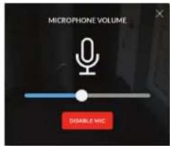
Microphone Volume (Option available for cameras that support audio.) Click to adjust the microphone volume used to record audio input for a recording. You can adjust the volume by dragging the slider horizontally.
text_image
MICROPHONE VOLUME DISABLE MHC- Disable Mic To disable the microphone, click Disable Mic, and then click Yes, Disable Microphone to confirm.

Note: To re-enable the microphone, the camera must be set to its factory default settings.

Note: UniFi Video Cameras can be reset to factory defaults using one of the following methods:
- Camera's WEB UI
• SSH - Camera's Physical Reset Button
Audio Output (Option available for cameras that support audio.) Click to mute or unmute the live view audio feed of the camera.
Close Click ✗ to close the Camera Details window and exit back to the home screen.
Video
Resolution
Resolution in this section refers to video output quality expressed in total pixels: image length (horizontal) x image height (vertical).

bar
Resolution Override Suggested Settings ON | Resolution | FPS | Bitrate | | :--- | :--- | :--- | | HIGH (1920 X 1080) | 15 | 3000 Kbps | | MEDIUM (1024 X 576) | 15 | 1000 Kbps | | LOW (640 X 360) | 15 | 500 Kbps |Override Suggested Settings Click to enable or disable manual override of the selected camera's resolution settings. With Override Suggested Settings set to ON, you will be able to adjust FPS (frames per second, also known as frequency), and Bitrate, for the video output at each resolution: High, Medium, and Low.

Note: The displayed resolution (n X n) for High, Medium, and Low is hardware-dependent.
High/Medium/Low (n X n)
FPS Drag the slider to choose a frame rate for the selected camera's video output resolution.
Bitrate Drag the slider to choose a bitrate for the selected camera's video output resolution. The bitrate is selectable in 100 Kbps increments.
On Screen Display

text_image
On Screen Display Override Message ON Message Timestamp Overlay ON Watermark ONOverride Message Click to enable or disable message override. When enabled, enter the text, for example, Rob's Office, that you want to be displayed on the video feed for the selected camera.
Timestamp Overlay Click to enable or disable the timestamp from appearing on the live video feed.
Watermark Click to enable or disable the visibility of the watermark on the live video feed of the selected camera.
Accessories

text_image
Accessories Enable Status LED ON Enable Speaker ON Enable System Sounds ONEnable Status LED (Available on UVC-G3 Dome and UVC-G3-Micro.) Click to enable or disable the status LED on the camera.
Enable Speaker Enable for two-wa communication
Enable Ssytem Sounds Enables or disables informational tones, such as WiFi or controller disconnects.
RTSP/RTMP/RTMPS Services
RTSP Service (Real Time Streaming Protocol), RTMP Service (Real Time Media Protocol), and RTMPS Service (Real Time Media Protocol over SSL) are network protocols designed for facilitating the playback of media files. These settings allow you to enable RTSP/RTMP/RTMPS service(s) for each of the camera's resolutions (High, Medium, and Low).

Note: The displayed resolution (n X n) for High, Medium, and Low is hardware-dependent.

text_image
RTSP Service High (1920 X 1080) OFF Medium (1024 X 576) OFF Low (640 X 360) OFF RTMP Service High (1920 X 1080) OFF Medium (1024 X 576) OFF Low (640 X 360) OFF RTMPS Service High (1920 X 1080) OFF Medium (1024 X 576) OFF Low (640 X 360) OFFClick to enable/disable the toggle switch ON or OFF for each resolution under the specified service.
Recording Configuration

text_image
Configuration Record Mode Record only motion Resolution High (1260 x 720)Record Mode Allows you to define the recording mode of the selected camera.
- Don't change This option only appears when multiple cameras are selected. Choosing this option keeps the cameras in their current recording mode.
- Don't record Nothing will be recorded by the camera.
• Always record Enables the camera to record all the time, regardless if there is motion detected or not. - Record only motion All captured images are analyzed and only recorded when motion is detected.
- Record on schedule Allows you to set up a specific recording schedule for each individual camera. Choosing this Record Mode will display a Schedule option. Click the Schedule drop-down menu to create a new schedule or select from a list of existing schedules.
- New Schedule To create a new recording schedule, click and drag a block of time on each day you would like the camera to record. When you are finished, click Save. You can also update or delete an existing schedule by clicking to view it in edit mode.

text_image
Sunday 01:00 02:00 03:00 04:00 05:00 06:00 07:00 08:00 09:00 10:00 11:00 12:00 13:00 14:00 15:00 16:00 17:00 18:00 19:00 20:00 21:00 22:00 23:00 24:00 25:00 26:00 27:00 28:00 29:00 30:00 31:00 32:00 33:00 34:00 35:00 36:00 37:00 38:00 39:00 40:00 41:00 42:00 43:00 44:00 45:00 46:00 47:00 48:00 49:00 50:00 51:00 52:00 53:00 54:00 55:00 56:00 57:00 58:00 59:00 60:00 61:00 62:00 63:00 64:00 65:00 66:00 67:00 68:00 69:00 70:00 71:00 72:00 73:00 74:00 75:00 76:00 77:00 78:00 79:00 80:00 81:00 82:00 83:00 84:00 85:00 86:00 87:00 88:00 89:00 90:00 91:00 92:00 93:00 94:00 95:00 96:00 97:00 98:00Resolution Choose one of the following three resolutions to use for the selected camera: High, Medium, or Low.

Note: The displayed resolution for High, Medium, and Low is hardware-dependent.
Motion Detection
text_image
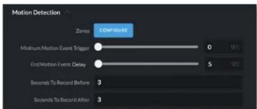
Motion Detection Zones CONFIGURE Minimum Motion Event Trigger 0 SEC End Motion Event Delay 5 SEC Seconds To Record Before 3 Seconds To Record After 3Ubiquiti Networks, Inc.
Zones Click Configure to edit motion zones for the selected camera. This option does not appear if multiple cameras are selected, as zones are configured individually.
Minimum Motion Event Trigger Drag the slider control left or right to set the minimum duration (0 to 10 seconds) that motion must take place to trigger recording.
(X Seconds Before -> Actual Motion -> X Seconds After Motion)
End Motion Event Delay The number of seconds that must elapse before a camera considers motion to have stopped.
Seconds To Record Before Enter the number of seconds you want UniFi Video to record before the triggering motion occurs on the selected camera.
Seconds To Record After Enter the number of seconds you want UniFi Video to record after the triggering motion occurs on the selected camera.
Configuring a Zone
text_image
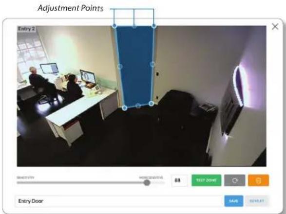
Adjustment Points Entry 2 Entry Door HKEYSOUTH HKEYSOUTH 88 TEST ZONE OK ADD SAVE REVEEBy default, the initial zone for each camera is the entire viewing area captured in the live feed window. Click and drag the Adjustment Points from each corner of the window to the perimeter of the area you would like to define as your zone. Only motion within this zone will trigger recording.
Click to test the zone you just created and adjust the sensitivity using the Sensitivity Slider control. Image trails will appear when motion is detected and the sensitivity level and motion spikes will appear in the bottom right corner of the camera feed. The sensitivity level (from 0 to 100) is shown in the box to the right of the slider control. As various degrees of motion occur, you'll see different level spikes. Adjust the sensitivity to a level that best suits your needs. Motion spikes that exceed the defined sensitivity threshold will be recorded when motion recording is enabled. Click Test Zone again to stop the test.
Chapter 2: Cameras UniFi Video User Guide
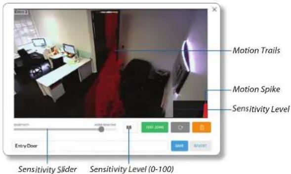
text_image
Entry 2 Motion Trails Motion Spike Sensitivity Level Entry Door Sensitivity Slider Sensitivity Level (0-100)
Click to refresh the camera image that appears in the zone preview.

Use this button to delete the current zone. Click an area of the camera feed to define another zone after deleting the existing zone.

Enter a name or brief description of the zone you are creating, in the text field provided. In this example, Entry Door is used.

Click Save when you are done configuring and naming your new zone.

Click Revert to cancel all changes and restore the previous settings.
Status

line
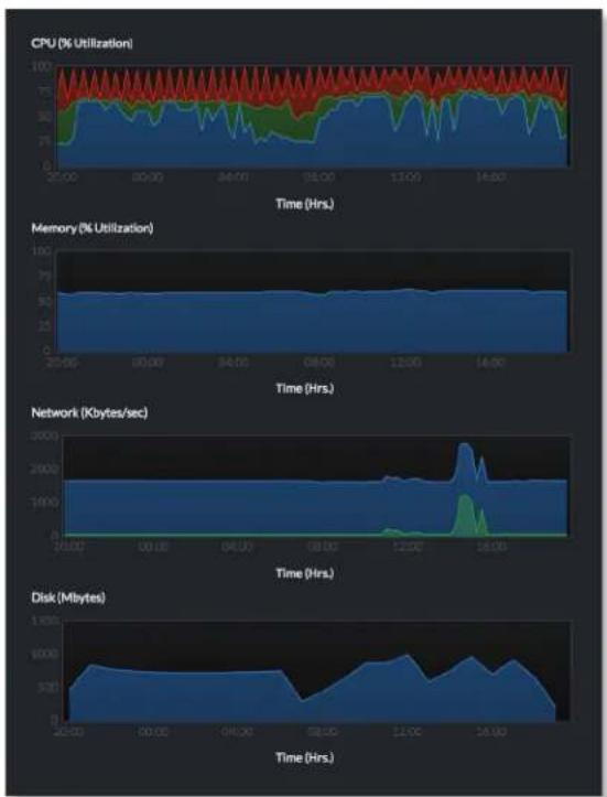
| Metric | Time (Hrs.) | | --- | --- | | CPU Utilization (%) | 100 | | Memory Utilization (%) | 100 | | Network (Kbytes/sec) | 120 | | Disk (Mbytes) | 25 |CPU (% Utilization) Displays the camera's CPU utilization recorded over 24 hours with high, low, and average points highlighted. Red indicates the highest point, green is the average, and blue is the lowest point during sampled intervals.
Memory (% Utilization) Displays the percentage of the camera's memory utilization over a 24-hour period.
Network (Kbytes/sec) Displays the network traffic for the selected camera over the last 24 hours. Graph is expressed in kilobytes per second.
Disk (Mbytes) Displays the amount of disk usage for the selected camera over the last 24 hours. Graph is expressed in total megabytes.
Manage

text_image
Configuration Host 192.168.10.203 Alias QA UVC G3 AF1 Controller Settings Controller Host 192.168.1.35 Controller Port 7442Configuration
Host Displays the local IP address configured for the camera you are currently viewing.
Alias Displays the device name configured for the live feed window for each camera. This is different from the name described for "On Screen Display" on page 10.
Controller Settings
Controller Host The IP address that the camera should use to communicate with the controller. This setting is typically used in environments where the UniFi Video server has multiple active network interfaces. Controller Port The port that the camera should use to communicate with the controller. Beginning with version 3.8.0, this has been separated from the web management port (default 7443) for security purposes.
Unmanage

text_image
Unmanage Remove Unlocked Recordings UNMANAGEClick Unmanage if you no longer want to manage the selected camera. If you wish to remove unlocked recordings for that particular camera as well, check the box labeled Remove Unlocked Recordings.
text_image
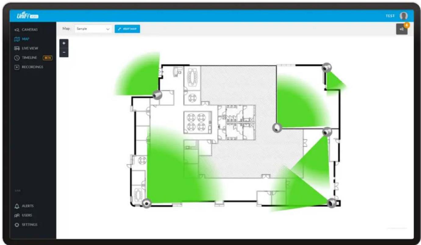
UniFi TEST CAMERAS MAP LIVE VIEW TIMELINE BETA RECORDINGS Map: Sample EDIT MAP AID ALERTS PRL USERS SETTINGSChapter 3: Map
The Map page allows you to upload custom map images of your site or floor plan, including aerial locations from Google Maps ^™ for a visual representation of your camera layout.
The map also indicates if motion has been detected on a camera. The color of each camera's field of view varies from red (motion currently detected) to green (no recent motion).
Defining a Map
You can add an image you've created as a map image or use Google Maps to generate an image for use as a background.
Image Map
To add a custom map, you must first create the image using an illustration, image editing, or blueprint application that exports .jpg, .gif, or .png file formats.
Once you've created the map, you can upload it to the UniFi Video software by performing the following steps:
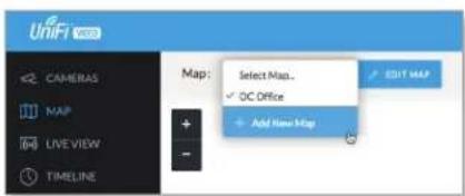
- Click Add New Map in the Map drop-down menu.

text_image
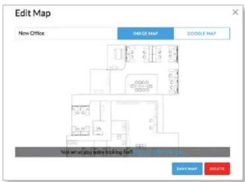
UniFi CAMERAS MAP LIVE VIEW TIMELINE Map: Select Map... ✓ OC Office + Add New Map EDIT MAP- Enter a map name in the Enter new map name field and click Image Map.
text_image
Edit Map New Office IMAGE MAP GOOGLE MAP High set up your entire booking for 5 SAVE MAP DELETE-
Select the file to use as a map (valid file formats are .jpg, .gif, and .png). Click Open.
-
Click Add Map.
-
Zoom in on the map using the button on the left. Zoom out using the button.
Chapter 3: Map UniFi Video User Guide
- Click the button in the upper right corner to bring up a list of cameras for placement. Drag the camera from the Cameras list on the right to the appropriate location on the map. The camera will appear in the area it was placed.

text_image
Floor plan interface screenshot showing room layouts and furniture layout with Chinese labelsGoogle Map
To create a custom map using Google Maps, perform the following steps:
- Click Add New Map in the Map drop-down menu.
text_image
UniFi 3.0 CAMERAS MAP LIVE VIEW TIMELINE Map: Select Map... ✓ OC Office + Add New Map EDIT MAP- Enter the desired address in the Enter location field and click Locate.

text_image
New Map Enter new map home THREE MAP GOOGLE MAP Map: Satellite Solar Location CREATE ADD MAP STARTS-
Enter a map name in the Enter new map name field and click Add Map.
-
Zoom in on the map using the button and zoom out using the button.
-
Click the button in the top right corner to bring up a list of cameras for placement. Drag the camera from the Cameras list on the right to the appropriate location on the map. The camera will appear in the area it was placed.

Note: When using Google Maps, you must supply an API Key in the Maps Settings box under Settings.

text_image
http://www.3ds.com File Edit View Help Name: 012456789 Address: 012456789 Location: 012456789 Name: 012456789 Address: 012456789 Name: 012456789 Address: 012456789 Name: 012456789 Address: 012456789 Name: 012456789 Address: 012456789 Name: 012456-01245678 Address: 012456789 Name: 012456789 Address: 012456789 Name: 012456789 Address: 012456789 Name: 012456789 Address: 012456789 Name: 0124Camera Placement
Camera thumbnails can be placed on the map to show the location of your cameras. To reposition a camera on the map, click and hold the Camera thumbnail and then drag the camera to another location on the map.

text_image
Suite C Entry from AClick and drag the black dot to adjust the camera's direction and field of view.
Click the Camera icon to reveal additional options: Live Feed Details, and Remove.
Live Feed
Click the Live Feed Ⓞ icon to bring up the camera's Live Stream window. The details are described in "Live Stream Window" on page 9.
Details
Click the Camera Details icon to bring up the Camera Details page. The details are described in "Cameras" on page 7.
Delete
Click the icon to remove the camera from the map.

text_image
UNIFT CAMERA MAP LIVE VIEW TIMESARY RECORDING All Camera Layout 36 Camera ACCESS NAME SAVE ALERTS AFL USERS SETTINGChapter 4: Live View
You can monitor multiple camera feeds through a single view layout using the Live View page. There are 12 pre-defined templates that support up to 26 cameras. Live View allows you to select which camera layout to use and which video feeds to display in that particular layout.
Create a New View
To create a custom Live View, follow these steps:
- Click the drop-down box at the top left of the window. Click New View.

- Select a layout by clicking one of the templates in the Choose a Layout window.

text_image
Choose a Layout 1 Camera 4 Camera 6 Camera 7 Camera 8 Camera 9 Camera 10 Camera 11 Camera 12 Camera 13 Camera 14 CameraUbiquiti Networks, Inc.
- Do the following for each of your cameras:
a. Click the Camera Select icon in the bottom right corner of a video feed area to display the list of available cameras.

text_image
New Layer 3D Camera Layer 12 Camera Add Camera Remove Office Browse Image Carbohydrate Based Box Carbohydrate Based Post Browse Image Demographic Box 1 Remove Box Office Membrane Open Office 2 Presetscale Box Office Remove Box Subs. Add Store Subs. Add Office Box Subs. Add Open Office Subs. Add Press Subs. Add Broadcast Box Subs. Add Broadcast Center Subs. Add Email Subs. Add Email Advancedb. Assign the camera to the video feed area using one of the following methods:
- Select a camera from the list.
- Search for a camera name (or part of a name) by entering it into the Search field at the top of the list.
- Select Advanced at the bottom of the list to open the Advanced dialog. Then select the camera from the drop-down list and select the Cycle On setting: Motion or Time Interval.
- The cameras will appear in the areas of the layout and you will see their live video feeds in the Live View window.
Chapter 4: Live View UniFi Video User Guide
- To view or modify the details of any camera in your layout, click the Configure icon and refer to "Camera Details Window" on page 8.
- Save the layout by entering a name or brief description in the View Name text field and clicking Save on the right side of the menu bar. Or, click Delete to delete the view without saving it.

Edit a View
To edit an existing Live View, follow these steps:
- Display the view that you want to edit by selecting it from the drop-down list. Then click Edit View.

-
Edit the view using the icons displayed in the video feeds of the layout:
-
Camera Select Click this icon to assign a different camera to the video feed.
- Configure Click this icon to display the camera details window (described in detail in "Camera Details Window" on page 8).
- Camera Settings Click this icon to configure various image settings such as Brightness, Contrast, Hue, Saturation, Denoise, Sharpness, WDR, AE Mode, Orientation, and Infrared.
- Snapshot Click this icon to download a snapshot of the current view.
- Camera Resolution Click this icon to set the camera's resolution to one of the following settings: Auto (Medium), High, Medium, Low.
- Microphone Volume Click this icon to configure the camera's microphone. Drag the slider to the left or right to adjust the volume for recording audio input, or click Disable Mic to disable the microphone.

Note: If the microphone is disabled, the volume icon will not appear in the toolbar. To re-enable the microphone, you will have to manually reset the camera to factory defaults by pressing its reset button.
- Audio Click this icon to mute or unmute the audio.
- Save the edited layout by clicking Save on the right side of the menu bar. Click Revert to cancel the changes you've made to the view.
Renaming a View

natural_image
Six-panel collage of an office interior showing various workstations and desks, with no visible text or symbols.You can rename an existing view or layout by performing the following steps:
- Click the drop-down list of existing camera layouts and select the view you want to rename. In this example, we will use Front Office.
- Click Edit View next to the camera layout you selected and enter a new name for the layout.

- Click Save to save the changes you've made to the view. Click Revert to cancel the changes you've made to the view.
Deleting a View
You can delete an existing view or layout by performing the following steps:
- Click the drop-down list of existing camera layouts and select the view you want to delete.
- Click the Delete button to remove a view.

text_image
Confirm Delete Are you sure you want to delete this view?- When prompted, click Delete to confirm.

text_image
UniFi CAMERAS MAP LIVE VIEW TIMELINE RECORDINGS 2016-03-02 09:03:05 Entrance to Hall Entrance to Hall 05:00:13 PM 1x Mar 02 '16 1Hr 0:00 PM 0:00 PM 0:10 PM 0:15 PM 0:30 PM 0:25 PM 0:30 PM 0:28 PM 0:40 PM 0:45 PM 1:00 PM 0:15 PM 4:00 PMChapter 5: Timeline
The Timeline page allows you to selectively view the parts of recorded video clips where motion has been detected. You can also set the duration of video to play, adjust the playback speed, and move directly to any point in a clip. Keyboard shortcuts are also provided as a convenient method of control during playback.
Selecting a Clip for Playback
Selecting a clip to view involves the following steps:
- Select the camera whose video clip(s) you want to view.
- Select the playback date.
- Select the playback start time and duration.
- Select the playback rate.
Select Camera
- At the lower left of the video screen, click the drop-down box to display a list of available cameras.

text_image
Entrance to Hall 1st ▶ May 02 16 Camera List- Select the desired camera.
- If the camera has no recorded video clips, "No Video" is displayed; select another camera for playback.
Select Playback Date
- The playback date is displayed below the center of the video screen.

text_image
Emnance Hall Is > Mar 02 '18 Playback Date- To change the date, click it to display a calendar, and then select the desired date.

text_image
February 2016 8 M T W T F S 1 2 3 4 5 6 7 8 9 10 11 12 13 14 15 16 17 18 19 20 21 22 23 24 25 26 27 28 29 Be D Feb 15 '16- Click ✗ to close the calendar.
Select Playback Start Time and Duration
- The playback start time is displayed at the lower left side of the video screen.

text_image
VFC MicroDC 10:00 PM 12:00 PM 13:00 PM 14:00 PM 15:00 PM 16:00 PM 17:00 PM 18:00 PM 19:00 PM 20:00 PM 21:00 PM 22:00 PM 23:00 PM 24:00 PM 25:00 PM 26:00 PM 27:00 PM 28:00 PM 29:00 PM 30:00 PM 31:00 PM 32:00 PM 33:00 PM 34:00 PM 35:00 PM 36:00 PM 37:00 PM 38:00 PM 39:00 PM 40:00 PM 41:00 PM 42:00 PM 43:00 PM 44:00 PM 45:00 PM 46:00 PM 47:00 PM 48:00 PM 49:00 PM 50:00 PM 51:00 PM 52:00 PM 53:00 PM 54:00 PM 55:00 PM 56:00 PM 57:00 PM 58:00 PM 59:00 PM 60:00 PM 61:00 PM 62:00 PM 63:00 PM 64:00 PM 65:00 PM 66:00 PM 67:00 PM 68:00 PM 69:00 PM 70:00 PM 71:00 PM 72:00 PM 73:00 PM 74:00 PM 75:00 PM 76:00 PM 77:00 PM 78:00 PM 79:00 PM 80:00 PM 81:00 PM 82:00 PM 83:00 PM 84:00 PM 85:00 PM 86:00 PM 87:00 PM 88:00 PM 89:00 PM 90:00 PM 91:00 PM 92:00 PM 93:00 PM 94:00 PM 95:00 PM 96:00 PM 97:00 PM 98:00 PM 99:00 PM 12/1/24 12/1/25 12/1/26 12/1/27 12/1/28 12/1/29 12/1/3/3 12/1/3/4 12/1/3/5 12/1/3/6 12/1/3/7 12/1/3/8 12/1/3/9 12/1/3/12 12/1/3/13 12/1/3/14 12/1/3/15 12/1/3/16 12/1/3/17 12/1/3/18 12/1/3/19 12/1/3/2/3 12/1/3/2/4 12/1/3/2/5 12/1/3/2/6 12/1/3/2/7 12/1/3/2/8 12/1/3/2/9 12/1/3/2/12 12/1/3/2/13 12/1/3/2/14 12/1/3/2/15 12/1/3/2/16 12/1/3/2/17 12/1/3/2/18 12/1/3/2/19 12/1/3/2/2- To change the start time, use the and controls (Back and Forward, respectively) on the left and right sides of the window. Each click will move the start time forward or backward by half the value of the playback duration. For example, if the duration is one hour, clicking will move the start time back 30 minutes.
- The playback duration is displayed at the lower right of the video screen.
- To change the duration, click it to display a list of available values: 24 Hrs, 12 Hrs, 6 Hrs, 1 Hr, or 30 Min. Select the desired duration. The default is 1 Hr.
Select Playback Rate
- The playback rate is displayed below the center of the video screen.

text_image
Oculus to FM Playback Rate 1.00 fps 120 fps 150 fps 180 fps 220 fps 250 fps 300 fps 350 fps 400 fps 450 fps 500 fps 550 fps 600 fps 650 fps 700 fps 750 fps 800 fps- To change the rate, click it to display a list of available rates: 0.25x, 0.5x, 1x, 2x, 4x, or 8x. Select the desired rate. The default is 1x.
Playback
After you have selected the video clip, use the controls to view it. The controls include:
- Timeline The Timeline shows the start and end times of the video clip, with tick marks at regular intervals in between. Drag the slider advance directly to a specific point in the video.

- Motion Bar The Motion Bar contains red markers to show where motion has been detected in the video clip.

- Zoom When you position the cursor over the video screen, the Zoom control appears, allowing you to zoom in on specific parts of the video display, or to zoom back out. Use the slider control or the and buttons to adjust the zoom factor.

When you zoom in, a small box will appear in the upper-right corner of the video display, showing the zoomed-in area within the main field of view. To zoom in on a different area, click and drag the video screen until the desired area is displayed.

Control buttons used for playback include the following:

text_image
UVC-MHz DC Play/Pause Full-Screen Shortcuts- Click Play to start playing the clip. The playback automatically plays only the sections of the clip where motion has been detected.
- Click Pause to stop playing the clip.
- Click Full-screen to enlarge the video display to full-screen or reduce it from full-screen back to normal size.
- Click Snapshot to download a snapshot of the current view.
- Click Shortcuts to display a list of keyboard shortcuts:
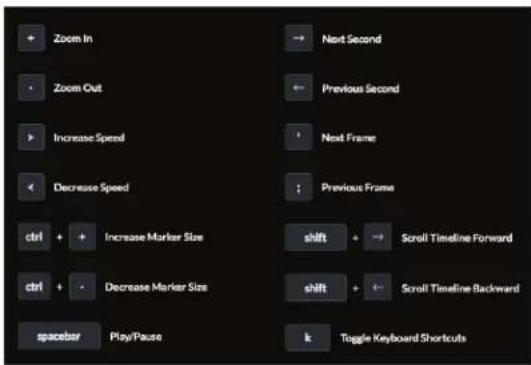
text_image
Zoom In Zoom Out Increase Speed Decrease Speed ctrl + Increase Marker Size ctrl + Decrease Marker Size spacer Play/Pause Next Second Previous Second Next Frame Previous Frame shift + Scroll Timeline Forward shift + Scroll Timeline Backward k Toggle Keyboard ShortcutsKeyboard shortcuts include:
-
- Zoom In – Changes the playback duration to the next lower value (for example, from 1 Hr to 30 Min).
- Zoom Out – Changes the playback duration to the next higher value (for example, from 1 Hr to 6 Hrs).
-
Increase Speed – Changes the playback rate to the next higher value (for example, from 1x to 2x).
- < Decrease Speed – Changes the playback rate to the next lower value (for example, from 0.5x to 1x).
- ctrl + Increase Marker Size – Increases the height of the markers in the Motion Bar.
- ctrl – Decrease Marker Size – Decreases the height of the markers in the Motion Bar.
- spacebar Play/Pause – Starts/stops playback.
- Next Second – Advances the video by one second.
- Previous Second – Moves the video back by one second.
- alt ▶ Next Frame – Moves the timeline forward one frame.
- alt ◀ Previous Frame – Moves the timeline back one frame.
- shift ▶ Scroll Timeline Forward – Moves the Timeline start and end times forward (later in time). This has the same effect as the >control.
- shift ◀ Scroll Timeline Backward – Moves the Timeline start and end times backward (earlier in time). This has the same effect as the <control.
- k Toggle Keyboard Shortcuts – Press k to toggle the display of keyboard shortcuts on and off.
When you are finished viewing the shortcut list, click ✗ to close the list.
Chapter 5: Timeline UniFi Video User Guide
text_image
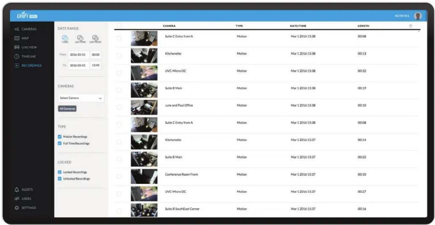
UniFi CAMERAS MAP LIVE VIEW TIMELINE RECORDINGS DATE RANGE Tally Last View Last Month From 2016-03-01 00:00 To 2016-03-01 15:45 CAMERAS Select Camera All Cameras TYPE ✓ Motion Recordings ✓ Full Time Recordings LOCKED ✓ Locked Recordings ✓ Unlocked Recordings CAMERA TYPE DATE/TIME LENGTH Suite C Entry from A Motion Mar 1 2016 15:38 00:08 Kitchenette Motion Mar 1 2016 15:38 00:13 UVC-Micro OC Motion Mar 1 2016 15:38 00:32 Suite B Main Motion Mar 1 2016 15:38 00:19 June and Paul Office Motion Mar 1 2016 15:38 00:10 Suite C Entry from A Motion Mar 1 2016 15:38 00:08 Kitchenette Motion Mar 1 2016 15:37 00:14 Suite B Main Motion Mar 1 2016 15:37 00:22 Conference Room Front Motion Mar 1 2016 15:37 00:10 UVC-Micro OC Motion Mar 1 2016 15:37 00:27 Suite B SouthEast Corner Motion Mar 1 2016 15:37 00:16
Chapter 6: Recordings
The Recordings page lets you search, sort, and view saved video recordings based on camera name, recording type, recording date, or length of video clip. Each of the following column headers is a clickable label that sorts the list of recordings alphabetically or numerically, depending on the type of data contained in that field: Camera, Type, Date/Time, and Length.
Camera Displays the local device name of each camera that recorded a video clip on the Recordings page.
Type Displays the type of recording that was made based on the recording mode defined in the camera details. The two types are Motion and Full Time.
Date/Time Displays the date and time each video clip was recorded.
Length Displays the length of each video clip recorded.
Date Range

Today Displays a list of all video recordings made within the last day (24 hours).
Last Week Displays a list of all video recordings made within the last week (7 days).
Last Month Displays a list of all video recordings made within the last month.

Ubiquiti Networks, Inc.
From Specify the beginning range of video recordings.
To Specify the ending range of video recordings.
Cameras

text_image
CAMERAS entry Select Camera Entry 2 New Suite Entry New Suite Entry B Office Entry All CamerasSelect Camera Allows you to filter your search by camera name. The Search option will narrow down the list of cameras as you type into the Search box, eliminating the ones that don't match your search string criteria.
All Cameras Click All Cameras to display the video recordings made by every camera.
Type

Motion Recordings Check this box to include motion-detection recordings.
Full Time Recordings Check this box to include full-time recordings.
Chapter 6: Recordings UniFi Video User Guide
Locked

Locked Recordings Check this box if you would like to include Locked Recordings in the list of video clips displayed in the Recordings window.
Unlocked Recordings Check this box if you would like to include Unlocked Recordings in the list of video clips displayed in the Recordings window.
Viewing Recordings
Play Click the video clip to open a window where you can view the recording. Use the controls displayed in the window as follows:
| Icon Name Function | |
| Play Click to start playing the video clip. The icon changes to the Pause icon. | |
| Pause Click to stop playing the video clip. The icon changes to the Play icon. | |
| Playback Rate Click to set the playback rate to one of the following: 0.25x, 0.5x, 1x, 2x, 4x, 8x. | |
| Mute Click to mute the camera's audio. The icon changes to the Unmute icon. | |
| Unmute Click to unmute the camera's audio. The icon changes to the Mute icon. | |
| Motion Indicator Click to enable or disable the motion detection indicator. When enabled, the indicator shows where motion occurred in the field of view using red shading. | |
| Snapshot Click to download a JPG of the current frame | |
| Microphone Two-way communication available on select cameras (UVC-Micro and UVC-G3-Micro). | |

text_image
2016-03-01 15:52:41 Corner Hall? 00:13/00:16 Info Camera Corner Hall Date/Time Mar 1 2016 15:52 Duration 00:15 Type Motion Unlocked DOWNLOAD DELETE
text_image
2016-03-01 15:52:29 Corner Hall?Motion Detection (red-shaded areas)
Info
Click any recording to display the details and options for the selected video clip.
Camera Displays the name of the camera.
Date/Time Displays the date and time the video clip was recorded.
Duration Indicates the length of the video clip.
Type Displays the type of recording that was made.
Unlocked Changes the status of a video clip recording between Locked and Unlocked. If a recording is unlocked, the video clip can be deleted by an administrator. If a recording is locked, the video clip cannot be deleted.
Download Click Download to save a copy of the selected camera recording to your computer as an MPEG4-formatted video.
Delete Click Delete to initiate removal of a video clip from the current list of recordings. A video clip can only be deleted if it is designated as Unlocked.

text_image
Confirm Delete Delete 1 recording? CANCEL DELETEWhen prompted to confirm deletion, click Delete to permanently delete the selected recording, or click Cancel to keep it.

text_image
UniFi CAMERAS MAP LIVE VIEW TIMELINE RECORDINGS DATE/TIME MESSAGE Fri, Feb 26 2016 1:36 PM Camera UVC-Micro OC requests management. DELTE Wed, Feb 24 2016 12:02 PM Camera Aaron I Office requests management. DELTE Mon, Feb 15 2016 9:28 PM Camera Suite C G3 Dome was discovered and is available for management. DELTE Fri, Dec 11 2015 1:39 PM Camera UVC G3 Dome was discovered and is available for management. DELTE Mon, Dec 7 2015 11:28 AM Camera UVC G3 was discovered and is available for management. DELTE Wed, Nov 11 2015 12:32 PM Camera UVC2 requests management. DELTE Wed, Nov 11 2015 12:32 PM Camera UVC2 was discovered and is available for management. DELTE Wed, Nov 11 2015 11:53 AM Camera UVC G3 Bullet was discovered and is available for management. DELTE Tue, Nov 10 2015 4:11 PM UniFi Video update v3.2.0-alpha12 is available. DELTE Tue, Nov 10 2015 4:11 PM Camera Suite A G3 Dome was discovered and is available for management. DELTE Tue, Oct 13 2015 1:02 PM Camera Micro Rob requests management. DELTE Tue, Oct 13 2015 1:02 PM Camera Rob Office requests management. DELTE Tue, Oct 13 2015 1:02 PM Camera Upstairs Front requests management. DELTEChapter 7: Alerts
(The Alerts section is available to administrators only.) Alerts and messages can be sorted by date or message type, including software updates, camera discoveries, and requests for management.
Alerts Home Page
Date/Time Displays the day of week, date, and time that an event occurred.
Message Displays a description of each event recorded by the NVR.
If you would like to remove a message from the list of alerts, click Ⓞ DELETE next to the corresponding event you would like to delete.
Click any message to view specific details of the device recorded in the selected event. Details and options will vary based on the type of device being reported. Refer to "Cameras" on page 7.
Chapter 7: Alerts UniFi Video User Guide

text_image
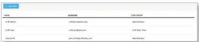
UniFi 2000 CAMERAS MAP LIVEVIEW TIMELINE RECORDINGS ADD USES NAME USERNAME USER GROUP UniFi Admin unifiadmin@ubnt.com Administrator UniFi User unifiuser@ubnt.com UniFi User View John Smiths john.smith@unifivideo.com AdministratorChapter 8: Users
(The Users section is available to administrators only.) This section allows you to manage user accounts on the NVR.
Name Displays the user's full name.
Username Displays the user's email address. This email address is used to log into the NVR.
User Group Displays the name of the user group that each NVR user belongs to.
User Details
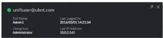
text_image
unifiuser@ubnt.com Full Name: Last Logged Inc Admin1 2016/03/01:14:21:34 Usergroup: Last IP Address Administrator 10.0.2.161Click any user account to open the Details window for that particular user.
Full Name Displays the selected user's full name.
Usergroup Displays the name of the user group that the selected NVR user belongs to.
Last Logged In Displays the date and time when the selected user account last logged in to the NVR.
Last IP Address Displays the last IP address used to log in to the NVR (by the selected user account).
There are four clickable tabs below the user details: Account, API Access, Alert, and Delete. (Delete is not displayed if you are viewing your own account.)
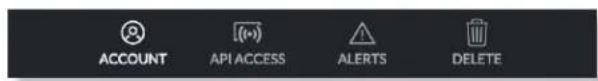
text_image
ACCOUNT API ACCESS ALERTS DELETEAccount

text_image
Full Name Admin1 Email Address Admin1@ubnt.com User Group Administrator Language English Local Access ON Username unifiuser@ubnt.com New Password Confirm PasswordFull Name View or edit the user's full name.
E-Mail Address View or edit the user's email address. This email address is used to log into the NVR.
User Group Select or edit the user group for this account. Click Edit to make changes to an existing user group. Refer to "New User Group" on page 27 for group options.
Language Select the user's language preference.
Chapter 8: Users UniFi Video User Guide
Local Access Used to turn local access on or off. When set to ON, the Username and Password options become available. These credentials are required when the cloud option is not being utilized.
Username The user name for the user account.
New Password Create a password for the selected user. This password will be used to log in and access the NVR.
Confirm Password Confirm the password by entering it a second time in the Confirm Password field.
API Access

text_image
Allow API Usage ON API Key 561fcd6aaca4f075 NEW API KEYAllow API Usage API stands for Application Programming Interface. Click to toggle ON and display the API Key field.
API Key Click New API Key to generate a key code when accessing UniFi Video from external applications.
Alerts
For a non-cloud UniFi Video installation, the Alerts tab appears as shown below:

text_image
ACCOUNT API ACCESS ALERTS Enable Alert Emails ON CAMERA ON DISCONNECT ON MOTION G3 Micro1 Never Never UVC Pro Never NeverEnable Alert Emails Click to enable or disable email alerts for specific cameras and events.
Camera Displays the camera name.
On Disconnect Indicates when to notify the administrator if the selected camera becomes disconnected. Select Never or Always.
On Motion Indicates when to notify the administrator if the selected camera records motion. Select Never or Always, or select New Schedule to define a schedule.
For a cloud-based UniFi Video installation, the Alerts tab appears as shown below:

text_image
ACCOUNT API ACCESS ALERTS CAMERA Alert Type: None Email Push ✓ Email & Push ON DISCON ON MOTION G3 Micro1 Never Never UVC Pro Never NeverAlert Types Select the type of alert to be received: None, Email, Push, or Email & Push.

Note: Push notifications requires your install to be connected to the cloud.
Camera Displays the camera name.
On Disconnect Indicates when to notify the administrator if the selected camera becomes disconnected. Select Never or Always.
On Motion Indicates when to notify the administrator if the selected camera records motion. Select Never or Always, or select New Schedule to define a schedule.
Alert Schedule for Motion Detection
To create a new schedule for motion detection alerts:
- Select New Schedule in the On Motion drop-down list.
- A window showing the days of the week and hours of the day will be displayed.

bar
| Day | Schedule Name | Amount ($) | |---|---|---| | Sunday | Send Alert 1 (mail) | 58.00 | | Monday | Send Alert 1 (mail) | 17.00 | | Tuesday | Send Alert 1 (mail) | 13.00 | | Wednesday | Send Alert 2 (mail) | 17.00 | | Thursday | Send Alert 2 (mail) | 17.00 | | Friday | Send Alert 2 (mail) | 17.00 | Schedule Name... SAVE CANCEL.- Select the periods to send an alert upon motion detection by dragging the cursor within the appropriate days of the week.
- Enter a name for the schedule and click Save.
To edit an existing schedule for motion detection alerts:
- Select the schedule from the On Motion drop-down list and click 🔒
- The schedule will be displayed in a separate window.
- Edit the schedule as needed.
- When done editing, click Save to save the changes.
To delete an existing schedule for motion detection alerts:
- Select the schedule from the On Motion drop-down list and click
- The schedule will be displayed in a separate window.
- Click Delete to delete the schedule.
Delete

text_image
ACCOUNT PASSWORD API ACCESS DELETE Are you sure you want to remove this user? REMOVE USERClick Delete to remove the selected user. When prompted to confirm removal of the user, click Remove User.

Note: This option is not available when viewing your own account.
Add User
text_image
NAME GENDER USD GROUP vW.Ashri vW.Ashri@ic.com Administrator vW.Ase vW.Ase@ic.com Unit New Year 2016.03.0 jsw@wjshri@ic.com AdministratorTo add a new user, click Add User on the top left corner of the window. The Create New User window will appear. Click each field and fill out the requested information. The Account and Password tabs are only required if you want this user to access the install via direct IP access; the API Access tab is optional. When you are finished, click Save.

text_image
Create New User ACCOUNT API ACCESS Full Name Email Address User Group Select User Group Language English Local Access ON Username Password Confirm Password SAVEAn e-mail invitation will be sent to the new user using the e-mail address you specified only if you are connected to the cloud. If you are not connected to the cloud, you must share the configured credentials with the intended user manually.

text_image
UniFi Video - microphy@ubst.com To you UnFi Video Input UniFi VIDEO Admin has invited you to connect to a NVRI. LXXXW Reply, Reply All or Forward | MoreUpon receipt of the e-mail invitation, the new user should click Login to accept the invitation and log into the UniFi Video system.
Account

text_image
Full Name Email Address User Group Select User Group Language English Local Access ON Username Password Confirm Password SAVEFull Name Enter the full name of the new user.
E-Mail Address Enter an email address for the new user. This email address will be used to log in to the NVR.
User Group Click Select User Group to display the User Group menu. Select an existing user group from the drop-down list or select New User Group to create a new group.
New User Group

text_image
User Group Select User Group Administrator New UniFi User Group Language + New User GroupChapter 8: Users UniFi Video User Guide
If you select New User Group, the following window will appear:

text_image
Can receive alert notifications via email CAMERAS VIEW CAMERA EDIT CAMERA VIEW RECORDINGS EDIT RECORDINGS Entry 2 ✓ ✓ ✓ Kitchesetra ✓ ✓ ✓ Suite B South Windows ✓ ✓ ✓ Uptain Front ✓ ✓ ✓ Aaron I Office ✓ ✓ ✓ Suite C Entry from A ✓ ✓ ✓ Corner Hall ✓ ✓ ✓ Server Room ✓ ✓ ✓ Entrance to Hall ✓ ✓ ✓ Suite C G3 Dome ✓ ✓ ✓ User Group Name... SAYS CREATE- Can receive alert notifications via email Check this box to grant users (in this group) the ability to receive email notifications when the NVR generates an alert message.
- View Camera, Edit Camera, View Recordings, Edit Recordings Select which cameras and recordings can be accessed by users in this group by clicking the checkbox next to each camera in the list.

Note: Some permissions are contingent on others. Therefore, as you select specific privileges, the system will automatically place a check mark next to the additional permissions required.
- User Group Name Assign the group a new name by entering it into the User Group Name field and click Save. You can also delete the group name by clicking Delete.
Language Select the user's language preference.
Local Access Used to enable or disable local access. If enabled (set to ON), the Username, New Password, and Confirm Password options are available.
Username The user name for the user account.
New Password Create a password for the selected user. This password will be used to log in and access the NVR.
Confirm Password Confirm the password by entering it a second time in the Confirm Password field. Passwords must match in both fields before UniFi Video will allow you to save the user account.
API Access

text_image
Allow API Usage ONAllow API Usage Click to enable or disable access to UniFi Video from an external application. When enabled, click New API Key to generate a new random key in the API Key text field.
API Key Use this key to authenticate access to UniFi Video from an external application.
When you are finished entering all of the information for the new user account, click Save.

text_image
UniFi V8B OC-NVR AARONJ UPDATE AVAILABLE GET SUPPORT FILE DOWNLOAD CONFIGURATION REVERT SAVE CAMERAS MAP LIVE VIEW TIMELINE DATA RECORDINGS OC-NVR SYSTEM CONFIGURATION 192.168.157.250 (xth0) Currently installed 3,9,0-alpha.3 CAMERA SETTINGS Any managed cameras will be updated to use this password. Camera Password ********** Camera Password should be different than your login password. Camera Adoption Token SELECT ORDER Use to adopt in Camera Web U: TIME & DATE Timezone (UTC-08:00) Pacific Time (US & Canada) ALERTS Minutes Between Motion Alert Emails 0 CONFIGURE ALERTS FIRMWARE UPDATES Check UBNT for Updates ON Report Statistics ON DEVICE DISCOVERYChapter 9: Settings
(The Settings section is available to administrators only.) The Settings section provides you with important system information and configuration options for your NVR.
System Configuration Click this button to configure your NVR's settings. Refer to "System Configuration" on page 30 for detailed information on System Configuration.
Get Support File Click this button to generate a support file for use by Ubiquiti customer support. This file only needs to be generated at their request.
Download Configuration Click this button to download your NVR's configuration to a file. (This doesn't include recordings). The configuration file is only used by the Setup Wizard when installing a new NVR.
Revert Click this button to cancel all changes you have made on the Settings page.
Save Click this button to save all changes you have made on the Settings page.
UniFi Video Cloud
Connect To My Ubiquiti Account/Disconnect From My Ubiquiti Account Click to connect or disconnect your UniFi Video installation from your Ubiquiti account. This enables or disables the free cloud access to your UniFi Video installation.
Camera Password
Camera Password The camera password, by default, is generated by UniFi Video's initial configuration wizard. Click this field to view the password in plain text, in the event you need to access a specific camera. You can also use this field to change the password used to access individual cameras. To save any password changes, you must also click Save in the upper right.

Note: This change will only apply to cameras that are currently managed by and connected to the UniFi Video server.
Camera Adoption Token A random adoption token can be generated to aide in the rapid adoption of multiple cameras. To use this feature, click New Token and a token will be generated in the field. The token is valid for 30 minutes from its generation and can be copied/pasted into the camera's web UI along with the IP address of the UniFi Video server for rapid camera management.

Note: The Adoption Token option only exists on cameras with firmware version 3.8.3 or newer.
Time & Date
Timezone Select the local time zone where the UniFi Video NVR is located.
Alerts
Minutes Between Motion Alert Emails Specify the number of minutes you want to separate recurring motion alert emails.
Configure Alerts Click Configure Alerts to customize the alert settings for each camera managed by the NVR. For information on configuring alerts, see "Alerts" on page 26.
[SMTP/Email Server (Only shown in installations that are not connected to the cloud) When not connected to the cloud, you may still receive camera disconnect and motion alert emails; however, push notifications are a cloud exclusive feature. In order to utilize this feature on an installation that is not connected to the cloud, you must toggle this feature On and then configure your SMTP server settings in conjunction with your email provider.
Firmware Updates
Check UBNT For Updates UniFi Video automatically checks for system updates but doesn't install them unless initiated by an administrator. If you don't want the NVR to automatically check for updates, click to toggle OFF.
Report Statistics (Available if Check UBNT for Updates is enabled.) Statistics are gathered and provided to Ubiquiti Networks for reference, in an effort to continually improve performance. To opt out, click to toggle OFF.
Device Discovery
Discover Cameras When set to ON, your NVR will automatically discover UniFi Video cameras as they become available on the network. To disable this feature, click to toggle OFF.
System Configuration
Click 📋 SYSTEM-COMPS SWITCH to open the System Configuration window. This will display the configuration details for the NVR.

text_image
SecondaryNVR IP Address: 192.168.1.35 CPU MAC Address: 24A43C06FB-C6 Memory Version: 3.9.0 Disk Model Name: UVC NVRIP Address Displays the current IP address of the NVR.
MAC Address Displays the hardware MAC address.
Version Displays the firmware version currently installed on the NVR.
Model Name Displays the model name of the NVR.
CPU Indicates the percentage of the CPU being utilized by the NVR.
Memory Indicates the amount of memory used by the NVR (expressed in gigabytes).
Disk Indicates the amount of disk space used on the NVR.
Configure
Configuration

text_image
CONFIGURE UPDATES STATS LOGS Configuration ^ Alias My NVR Recording Path /srv/unifi-video/videos Time Based Purging ON Time To Retain 1 Weeks Space To Keep Free 10 GB Tools ^ Database Synchronization ANALYZEAlias Displays the current name of the NVR.
Recording Path Path to where video clip recordings are stored on the NVR.
Time Based Purging When enabled, recordings are deleted after the amount of time specified in the Time To Retain field.
Time To Retain Defines the number of Hours, Days, or Weeks to keep recordings before deleting them. This option is available when Time Based Purging is set to ON.
Space to Keep Free Use the slider or text field to define how much space should be kept available on the NVR (expressed in gigabytes).

Note: This feature cannot be disabled.
Tools
Database Synchronization Allows you to analyze the current NVR database.
Updates

text_image
CONFIGURE UPDATES STATS LOGS UP TO DATE Currently Installed : 3.9.0 CHECK FOR UPDATES COMPATIBLE UPDATES No updates availableCurrently Installed Displays the firmware currently installed on your NVR. If it is the most recent firmware, "Up to Date" is also displayed.
Check for Updates Click to check the website for the latest firmware update (requires Internet connection). If an update is available, the version number will be listed with an Install button for easy upgrades through the web UI.
Stats
line
| Time (Hrs) | CPU (% Utilization) | Memory (% Utilization) | Network (Kbytes/sec) | Disk (Mbytes) | |------------|---------------------|------------------------|----------------------|---------------| | 25:00 | ~95 | ~60 | ~1000 | ~300 | | 00:00 | ~95 | ~60 | ~1000 | ~300 | | 04:00 | ~95 | ~60 | ~1000 | ~300 | | 08:00 | ~95 | ~60 | ~1000 | ~300 | | 12:00 | ~95 | ~60 | ~1000 | ~300 | | 16:00 | ~95 | ~60 | ~1000 | ~300 | | 21:00 | ~95 | ~60 | ~1000 | ~300 |CPU Displays percentage utilization of the NVR's processor over a 24-hour period.
Memory Displays percentage utilization of the NVR's memory over a 24-hour period.
Network Displays the amount of network activity over a 24-hour period (expressed in kilobytes).
Disk Displays the amount of disk activity over a 24-hour period (expressed in megabytes).
Logs
The Logs tab provides you with four separate log files generated by the NVR in the UniFi Video management system. Click Logs to display the current log activity. The default log is the Error log.

text_image
ERROR purge recording connection 1be19707c04d8 142894230.643 2015-04-13 09:26:26.107/FXT: ERROR Camera[7eb6f8fb-f5b-37a-8430-cd97 142894230.643 2015-04-13 09:26:20.870/FXT: ERROR Camera[731f645a-d900-3caa-8315-4edb5 142894230.643 2015-04-13 09:26:20.789/FXT: ERROR Camera[18f1c436-d82d-35aa-9037-lbm1 142894230.643 2015-04-13 09:26:20.643/FXT: ERROR Camera[ef200af3-b0as-36o9-22f1-4bf32 4bf32acbf7f81] 142894230.643 2015-04-13 09:26:20.511/FXT: ERROR Camera[021c97c4-a63c-33e9-a29b-sfdd afdd4952c0033] 1428942374.912 2015-04-13 09:26:14.912/FXT: ERROR Camera[7id8f1f-a9d-362c-Pod4-7819 "from","UniFiVideo,"to","ubnt_avoliont,"responseExpected":false,"functionName":"Dot "timeoutMe":10008,"what":"jpeg,"uri":"http://10.0.2.112/7080/camera/1.0/upload","for "securityToken":4611826755918556893","serverFilename":"lol.jpg","formFieldKeyServer [Entry 2] in tomat-HTTPD-exec=12 1428942374.910 2015-04-13 09:26:14.910/FXT: ERROR Camera[bdf5f43-a90e-3879-b5c3-b570 "from","UniFiVideo,"to","ubnt_avoliont,"responseExpected":false,"functionName":"Dot "timeoutMe":10008,"what":"jpeg,"uri":"http://10.0.2.112/7080/camera/1.0/upload","for "securityToken":4611826755918556914","serverFilename":"lol.jpg","formFieldKeyServer (Kitchenette) in tomat-HTTPD-exec=0 1428942374.908 2015-04-13 09:26:14.908/FXT: ERROR Camera[a19id929-769d-36bf-b0cb-bffie "from","UniFiVideo,"to","ubnt_avoliont,"responseExpected":false,"functionName":"Dot "timeoutMe":10008,"what":"jpeg,"uri":"http://10.0.2.112/7080/camera/1.0/upload","for "securityToken":4611826755918556848","serverFilename":"lol.jpg","formFieldKeyServer (Mov Suite Entry B) in tomat-HTTPD-exec=9 1428942374.908 2015-04-13 09:26:14.908/FXT: ERROR Camera[088d30ae-ac15-39a-89Ff-a82c "from","UniFiVideo,"to","ubnt_avoliont,"responseExpected":false,"functionName":"Dot "timeoutMe":10008,"what":"jpeg,"uri":"http://10.0.2.112/7080/camera/1.0/upload","for "securityToken":4611826755918556848","serverFilename":"lol.jpg", "formFieldKeyServer (June and Paul Office) in tomat-HTTPD-exec=5 1428942371.570 2015-04-13 09:26:11.570/FXT: ERROR Camera[1064ebhd-bd4b-379c-8644-325c 325cc26c3ea 1428942376.943 2015-04-13 09:26:10.942/FXT: ERROR Camera[25lbe917-55-coa-975-26lbc 2f1b6ad49f12] 1428942376.943 2015-04-13 09:26:10.942/FXT: ERROR Camera[ef200af3-a63c-33e9-a29b-sfdd afdd4952c0033]Error Displays a running log of all error messages.
Purge Displays a running log of all purge activity.
Recording Displays a running log of all recording activity.
Connection Displays a log of all connection activity, including loss of connection.
You can also delete, download, or refresh the view of any log activity by clicking one of the toolbar icons located in the upper right corner of the Logs screen.
Delete ☐ clears the log file currently displayed on your screen, without saving a copy to your computer.
Download Allows you to save a log file to your computer.
Refresh Updates the running log activity on your screen.
Chapter 9: Settings UniFi Video User Guide
Appendix A: Mobile App
UniFi Video is now accessible from iOS and Android™ smartphones and tablets using the UniFi Video mobile app. This appendix describes how to use the app on your mobile device to communicate with an NVR over the internet (cloud access).
UniFi Video App for iOS
- If you have not connected your Ubiquiti account to the NVR, do so now as described in "UniFi Video Cloud" on page 29.
-
On your smartphone or tablet, download the free UniFi Video mobile app for iOS from the iTunes® App Store.
-
Open the UniFi Video mobile app. The Sign In screen appears:
-
The Select NVR screen appears. Select the desired NVR from the list.
-
To sign in using your Ubiquiti user account, enter your E-mail address or Username and Password, and then tap Sign In. Go to step 7.
Note: If you do not have a Ubiquiti account, tap Register, enter all requested info, and tap Register. Then connect the account to your NVR as described in "UniFi Video Cloud" on page 29 before continuing.
- To connect directly to an NVR without signing into your Ubiquiti account, tap Connect directly to your NVR.
If the NVR you want is not displayed in the list, you can add it as follows:
a. Tap the more options icon, and then tap Add New NVR.
b. Enter the NVR's IP address and your Username and Password. Then tap Sign In.
If you don't know the NVRs IP address, use the search function as follows:
a. Tap the more options icon, and then tap Search for NVR.
b. Newly discovered NVRs will be displayed with next to the name.
Appendix A: Mobile App UniFi Video User Guide
- The app opens. By default, the Cameras screen appears:

text_image
Multi-View Break Room Last Recording Today 1:46 PM CONNECTED Conference Room Back Last Recording February 18 CONNECTED Conference Room Front Last Recording Today 1:46 PM CONNECTED Corner Hall Last Recording Today 12:09 PM CONNECTED Entrance to Hall Last Recording Today 1:47 PM CONNECTED Entry 2 Last Recording Today 1:47 PM CONNECTED Cameras Recordings SettingsThe menu bar at the bottom of the screen has icons used to navigate between the main screens:
- Tap to display the Cameras screen (already selected by default).
- Tap to display the Recordings screen.
- Tap to display the Settings screen.
Cameras Screen
The Cameras screen displays a list of cameras that are known to the UniFi controller. For each camera in the list, the following information is displayed:
- A thumbnail image of the camera's view (image is faded if the camera is offline).
• The name of the camera. - Date and time of two different events, depending on the connection status:
- Connected: The date and time of the last recording, or N/A if no recordings are available.
- Not connected: The date and time when the camera was last seen by the UniFi Video controller.
- The camera's connection status: Connected or Disconnected.
On the Cameras screen, you have the following options:
- Select a camera from the list to open the Camera Detail screen which contains a live video feed from the camera as well as information on the camera.
- At the top of the screen, tap 📄 Multi-View to open the Multi-View screen, which displays live feeds from four cameras.
Camera Detail
The Camera Detail screen displays a live video feed from the selected camera, as well as specific details on the camera, including its name, status, IP address, and software version.

text_image
No SIM 12:27 PM QA UVC G3 AF1 STEP IN 10:27:55 QA UVC G3 AF1 LIVE STREAM QA UVC G3 AF1 IP Address : 192.168.10.203 Firmware : v3.8.61 Status : Connected Record Made : None Record Resolution : High Recent RecordingsIcons located just below the Camera Detail screen provide the following controls:
| Icon Name Function | ||
| || | Pause Tap to | pause the live video stream. The icon changes to the Play icon. |
| ▷ | Play Tap to | resume the live video stream. The icon changes to the Pause icon. |
| Enhance (Available only on select G3 cameras. The G3 Pro does not support Magic Zoom). This feature lets you set a camera's view to a specific part of its full field of view. After zooming in (pinch to zoom), tap this icon and then tap Continue to make the zoomed-in view persist. To disable the zoomed-in view and restore the camera's full field of view, tap the icon again. | ||
| Mute Tap to | mute the camera's audio. The icon changes to the Unmute icon. | |
| Unmute Tap to | unmute the camera's audio. The icon changes to the Mute icon. | |
| Full-screen | Tap to toggle the video display between normal size and full-screen display. (Not available on all models; if not available, rotate the device between landscape and portrait mode to switch views.) | |

Note: When Enhance is selected, the new view will apply to the following:
- All live video from the camera.
- All recorded video from the camera.
- All motion zones for the camera.

Note: Depending on your mobile device's setup, the icon bar may contain additional icons not related to the UniFi Video mobile app.
Below the icon bar, the following information is displayed:
Camera Name Displays the name of the camera.
Camera Settings Tap Camera Settings to access camera settings:
- Motion Alert Sound (Available on UVC-Micro and UVC-Pro only) Set to On to enable the camera's motion alert sound, or set to Off to disable the motion alert sound.
- Camera LED (Available on UVC-Micro only) Set to On to enable the camera's LED, or set to Off to disable the LED.
- Image Settings Tap Image Settings to access the Image Settings screen.
IP Address Displays the IP address of the camera on the local network.
Firmware Displays the firmware version installed on the camera.
Status Displays Connected or Disconnected.
Record Mode Displays the recording mode: Off,
On Motion, or Always. To change the setting, tap the icon and select the new setting.
Record Resolution Displays the recording resolution:
High, Medium, or Low. To change the setting, tap the icon and select the new setting.
Recent Recordings Tap Recent Recordings to open a Recordings screen that lists recordings for the selected camera only.
Image Settings
The Image Settings screen lets you change the image settings for the live feed you are currently viewing. You can access this screen by tapping to the right of the camera name.

text_image
0000 AT&T 1:55 PM IMAGE SETTINGS Preview BRIGHTNESS CONTRAST HUE SATURATION 50Use the adjustment slider to modify each image property. The Image Settings window includes a live preview that updates as adjustments are made. Swipe the Image Settings menu horizontally to see additional image settings.
The image settings include the following:

Brightness Change the image brightness by moving the slider control left or right, from 0 (darkest) to 100 (brightest).


Contrast Change the image contrast by moving the slider control left or right, from 0 (least contrast) to 100 (greatest contrast).

Hue Change the image hue by moving the slider control left or right, from 0 (red end of spectrum) to 100 (purple end of spectrum).
Appendix A: Mobile App UniFi Video User Guide

SATURATION
Saturation Change the image saturation by moving the slider control left or right, from 0 (least saturated) to 100 (most saturated).


SHARPNESS
Sharpness Change the image sharpness by moving the slider control left or right, from 0 (least sharp) to 100 (sharpest).

DENOISE
Denoise Change the amount of image noise ("graininess") by moving the slider control left or right, from 0 (most noise) to 100 (least noise).


ORIENTATION
Orientation Change the orientation of the live feed window by selecting Flip Horizontally for a mirror image of the display or Flip Vertically for an upside-down image of the display. Select both options to flip the image horizontally and vertically at the same time.


INFRARED
Infrared Adjust the infrared setting for the live feed image by selecting Auto, On, or Off on the menu bar.


AUTO EXPOSURE
Auto Exposure Adjust the exposure setting for your live feed image by selecting Auto, 50 Hz, or 60 Hz on the menu bar.


WDR
WDR Adjust the WDR sensitivity level by selecting Lowest, Low, Mid, or High on the menu bar.

RESET
Reset Resets all of the Image Settings to their default values.

Multi-View Screen
The Multi-View screen displays live video feeds from four cameras. By default, the first four cameras listed in the Cameras screen are displayed.

natural_image
Interior view of a modern office space with multiple windows and ceiling equipment (no visible text or symbols)To access configuration options for a video feed, tap the video feed to display the following menu:

View

Switch

Fullscreen
To view a camera's live stream:
-
Tap the video feed to display the menu.
-
Tap View.
-
The Camera Detail screen will appear. (For more information, refer to "Camera Detail" on page 34.)
To change a video feed to display a different camera:
-
Tap the video feed to display the menu.
-
Tap Switch.
-
A list of cameras will be displayed. Tap a camera to select it.
-
The Multi-View screen will be displayed with the new camera in the video feed.
To enlarge a video feed to full-screen display:
-
Tap the video feed to display the menu.
-
Tap Fullscreen.
Recordings Screen
The Recordings screen displays a list of recently recorded video clips from all cameras that are known to the UniFi controller.

text_image
RECORDINGS March 7, 2016 0:10 1:53 PM Break Room 0:10 1:46 PM Break Room 0:10 1:44 PM Break Room 0:12 1:21 PM Break Room 0:12 1:19 PM Break Room 0:38 1:18 PM Break Room 0:08 1:17 PM Break Room 0:08 1:17 PM Break Room 0:12 1:15 PM Break Room Cameras Recordings Settings
Note: The recording of video clips is controlled by the recording preferences defined on the Cameras page of the UniFi Video app (see "Recording" on page 11) and on the Camera Detail screen of the mobile app (see "Camera Detail" on page 34).
For each recording in the list, the following information is displayed:
- A thumbnail image of the recording, superimposed with the length of the recording in minutes and seconds
• The starting time of the recording
• The name of the camera which made the recording. To view a recording, tap the recording to display the Recording Playback screen.
Tap the filter Icon in the top-right corner of the screen to display the filtering options: Date Range, Cameras, Type, and Locked.

Date Range
Select a specific date or range of dates to filter when listing the recent video recordings.

text_image
DATE RANGE CAMERA TYPE LOCKED Today : 4/13/15 Last Week : 4/6/15 - 4/13/15 Last Month : 3/13/15 - 4/13/15 Custom Range From : 4/6/15, 5:45 PM > To : >Today Displays a list of all recordings from today.
Last Week Displays a list of recordings from the last seven days.
Last Month Displays a list of recordings from the last month.
Custom Range Allows you to display a list of recordings based on a range of dates and times specified by the user.
• From Select the beginning date and time for your range.
• To Select the ending date and time for your range.
Cameras
Select specific cameras to view in the list of recent recordings. If no specific cameras are selected, then all cameras managed by the NVR will appear in the list.
Type
Allows you to select specific cameras based on their recording mode.
Record on Motion Include cameras that record on motion only.
Always Record Include cameras that record all the time, regardless of motion.
Locked
Locked Filters the view on recent recordings for video clips that are locked and cannot be deleted.
Unlocked Filters the view on recent recordings for video clips that are unlocked.
Appendix A: Mobile App UniFi Video User Guide
Recording Playback Screen
To begin playback of a recently recorded video clip, tap the clip in the Recordings screen list.
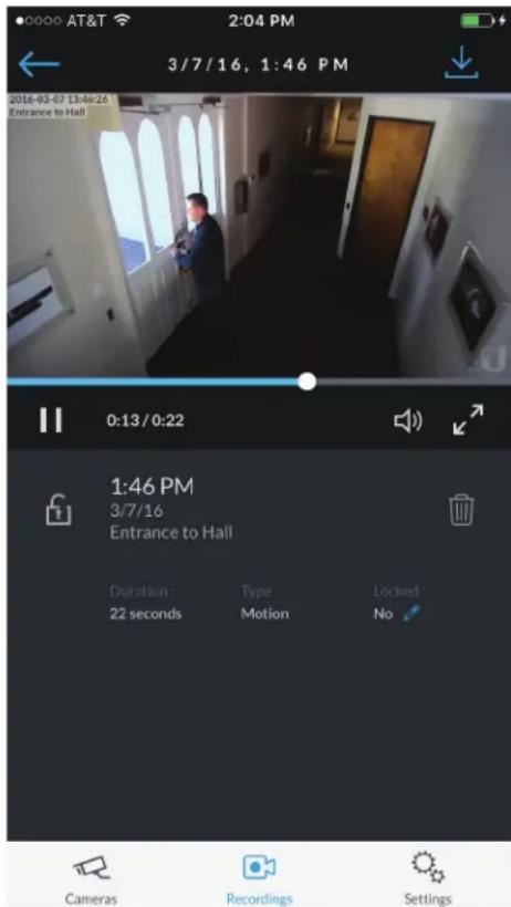
text_image
0:13/0:22 1:46 PM 3/7/16 Entrance to Hall Duration : Type : Locked : 22 seconds Motion No Cameras Recordings SettingsTap at the top-right corner of the screen to download the video clip to Camera Roll on your mobile device.
Icons below the recording playback screen provide the following controls:
| Icon Name Function | |
| Play Tap to play the recording. The icon changes to the Pause icon. | |
| II | Pause Tap to pause the recording. The icon changes to the Play icon. |
| Mute Tap to mute the recording's audio. The icon changes to the Unmute icon. | |
| Unmute Tap to unmute the recording's audio. The icon changes to the Mute icon. | |
Icons at the bottom of the recording playback screen provide the following controls:
| Icon Name Function | |
 | Locked Tap to unlock the video recording. The icon changes to theUnlockedicon. |
 | Unlocked Tap to lock the video recording. The icon changes to theLockedicon. |
 | Delete Tap and confirm to delete the video recording. |
The following information is displayed below the screen:
Duration The duration of the video clip.
Camera The name of the camera that recorded the video clip.
Type The recording criteria: On Motion or Always.
Locked The lock status: Yes (locked) or No (unlocked).
Settings Screen
To access the Settings screen, tap in the tab bar.

text_image
ATT 1:59 PM SETTINGS Sign Out Admin rob.rohm@ubnt.com OC NVR 10.0.2.112 Touch ID Use NVR Time Zone Local Time Zone Los Angeles NVR Time Zone Los Angeles Support Forum Knowledge Base Cameras Recordings SettingsSign Out Tap this option to sign out of the UniFi Video mobile app.
Use NVR Time Zone Select this option if you want the mobile app to use the NVR's time zone. This does not affect the NVR's time zone.
Local Time Zone This displays the local time zone of your mobile device.
NVR Time Zone This displays the time zone of the NVR.
Support Forum Tap this option to open the UniFi Video Support Forum in a web browser.
Knowledge Base Tap this option to open the UniFi Video Knowledge Base in a web browser.
UniFi Video App for Android
-
If you have not connected your Ubiquiti account to the NVR, do so now as described in "UniFi Video Cloud" on page 29.
-
On your smartphone or tablet, download the free UniFi Video mobile app for Android from the Google Play™ Store.

- Open the UniFi Video mobile app. The Sign In screen appears:
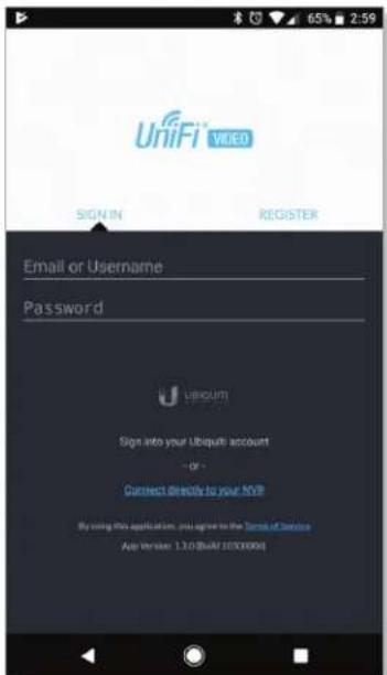
text_image
UniFi VIDEO SIGN IN REGISTER Email or Username Password U SIRCUIT Sign into your Ubiquit account - or - Connect directly to your NVP By using this application, you agree to the Terms of Service App Version: 1.1.0 (Web) (850000x)- To sign in using your Ubiquiti user account, enter your E-mail address or Username and Password, and then tap Sign In. Go to step 7.

Note: If you do not have a Ubiquiti account, tap Register, enter all requested info, and tap Register. Then connect the account to your NVR as described in "UniFi Video Cloud" on page 29 before continuing.
-
To connect directly to an NVR without signing into your Ubiquiti account, tap Connect directly to your NVR.
-
The Select NVR screen appears. Select the desired NVR from the list.
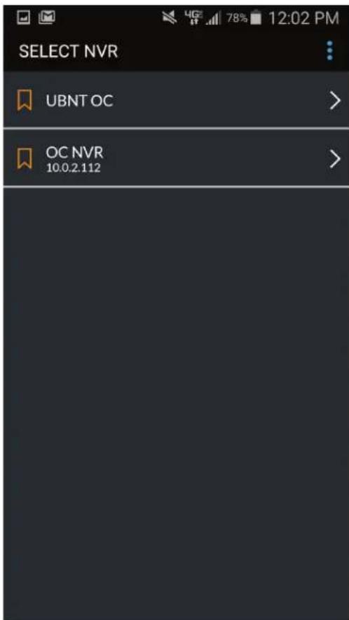
text_image
SELECT NVR UBNT OC > OC NVR 10.0.2.112 >If the NVR you want is not displayed in the list, you can add it as follows:
a. In the overflow menu ; tap Add New NVR. b. Enter the NVR's IP address and your Username and Password. Then tap Sign In.
If you don't know the NVRs IP address, use the search function as follows:
a. In the overflow menu ; tap Search for NVR. b. Newly discovered NVRs will be displayed with + next to the name.

- The app opens. By default, the Cameras screen appears:

text_image
CAMERAS Backyard East Last Recording 10/19/2017 7:02 AM CONNECTED Backyard North Last Recording 10/19/2017 2:11 PM CONNECTED Backyard West Last Recording 10/19/2017 7:03 AM CONNECTED Basement Last Recording 02/06/2017 9:19 AM CONNECTED Driveway Last Recording 10/19/2017 8:15 AM CONNECTED Exterior Gun Safe Last Recording 10/19/2017 1:41 PM CONNECTED Family RoomThe menu bar at the top of the screen has icons used to navigate between the main screens:
- Tap to display the Cameras screen (already selected by default).
- Tap to display the Recordings screen.
The overflow menu at the top right of the screen has the following options:
- Settings Tap Settings to display the Settings screen. Refer to "Settings Screen" on page 44 for detailed information on the Settings screen.
- Switch NVR Tap Switch NVR to display the Select NVR screen and select a different NVR.
- Sign Out Tap Sign Out to sign out of the UniFi Video mobile app.
Cameras Screen
The Cameras screen displays a list of cameras that are known to the UniFi controller. For each camera in the list, the following information is displayed:
- A thumbnail image of the camera's view (image is faded if the camera is offline).
• The name of the camera.
- Date and time of two different events, depending on the connection status:
- Connected: The date and time of the last recording, or N/A if no recordings are available.
- Not connected: The date and time when the camera was last seen by the UniFi Video controller.
- The camera's connection status: Connected or Disconnected.
On the Cameras screen, you have the following options:
- Select a camera from the list to open the Camera Detail screen which contains a live video feed from the camera as well as information on the camera.
- At the top right of the Cameras screen, tap the Icon to open the Multi-View screen, which displays live feeds from four cameras.
Camera Detail
The Camera Detail screen displays a live video feed from the selected camera, as well as specific details on the camera, including its name, status, IP address, and software version.

text_image
64% 3:07 LIVE STREAM Driveway Camera Settings JP Address: 192.168.1.14 Firmware: v4.1.8 Status: Connected Record Mode: On Motion Record Resolution: High Recent RecordingsIcons below the Camera Detail screen provide the following controls:
| Icon Name Function | |
| II | Pause Tap to pause the live video stream. The icon changes to the Play icon. |
| Play Tap to resume the live video stream. The icon changes to the Pause icon. | |
| Mute Tap to mute the camera's audio. The icon changes to the Unmute icon. | |
| Unmute Tap to unmute the camera's audio. The icon changes to the Mute icon. | |
| Microphone Two-way communication available on select cameras (UVC-Micro and UVC-G3-Micro). | |
The following control is located above the video screen:
Enhance (Available only on select G3 cameras. The G3 Pro will not support Magic Zoom). This feature lets you set a camera's view to a specific part of its full field of view. After zooming in (pinch to zoom), tap this icon and then tap Continue to make the zoomed-in view persist. To disable the zoomed-in view and restore the camera's full field of view, tap the icon again.

Note: When Enhance is selected, the new view will apply to the following:
- All live video from the camera.
• All recorded video from the camera.
• All motion zones for the camera.
Below the icon bar, the following information is displayed:
Camera Name Displays the name of the camera.
Camera Settings Tap Camera Settings to access camera settings:
- Motion Alert Sound (Available on UVC-Micro and UVC-Pro only) Set to On to enable the camera's motion alert sound, or set to Off to disable the motion alert sound.
- Camera LED (Available on UVC-Micro only) Set to On to enable the camera's LED, or set to Off to disable the LED.
• Image Settings Tap Image Settings to access the Image Settings screen.
IP Address Displays the IP address of the camera on the local network.
Firmware Displays the firmware version installed on the camera.
Status Displays Connected or Disconnected.
Record Mode Displays the recording mode: Off,
On Motion, or Always. To change the setting, tap the icon and select the new setting.
Record Resolution Displays the recording resolution:
High, Medium, or Low. To change the setting, tap the icon and select the new setting.
Recent Recordings Tap Recent Recordings to open a Recordings screen that lists recordings for the selected camera only.
Image Settings
The Image Settings screen lets you change the image settings for the live feed you are currently viewing. To access this screen from the Camera Detail screen, tap Camera Settings and then tap Image Settings.

text_image
Preview BRIGHTNESS CONTRAST HUE SATURATION 50Use the adjustment slider to modify each image property. The Image Settings window includes a live preview that updates as adjustments are made. Swipe the Image Settings menu horizontally to see additional image settings. The image settings include the following:

Brightness Change the image brightness by moving the slider control left or right, from 0 (darkest) to 100 (brightest).

Contrast Change the image contrast by moving the slider control left or right, from 0 (least contrast) to 100 (greatest contrast).

Hue Change the image hue by moving the slider control left or right, from 0 (red end of spectrum) to 100 (purple end of spectrum).
Appendix A: Mobile App UniFi Video User Guide

SATURATION
Saturation Change the image saturation by moving the slider control left or right, from 0 (least saturated) to 100 (most saturated).

SHARPNESS
Sharpness Change the image sharpness by moving the slider control left or right, from 0 (least sharp) to 100 (sharpest).


DENOISE
Denoise Change the amount of image noise ("graininess") by moving the slider control left or right, from 0 (most noise) to 100 (least noise).


ORIENTATION
Orientation Change the orientation of the live feed window by selecting Flip Horizontally for a mirror image of the display or Flip Vertically for an upside-down image of the display. Select both options to flip the image horizontally and vertically at the same time.


INFRARED
Infrared Adjust the infrared setting for the live feed image by selecting Auto, On, or Off on the menu bar.


AUTO EXPOSURE
Auto Exposure Adjust the exposure setting for your live feed image by selecting Auto, 50 Hz, or 60 Hz on the menu bar.


WDR
WDR Adjust the WDR sensitivity level by selecting Lowest, Low, Mid, or High on the menu bar.


RESET
Reset Resets all of the Image Settings to their default values.

Multi-View Screen
The Multi-View screen displays live video feeds from four cameras. By default, the first four cameras listed in the Cameras screen are displayed.
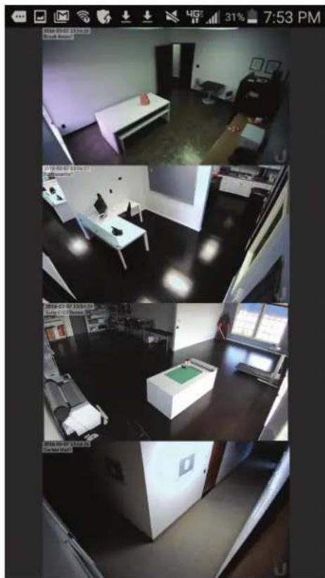
natural_image
Interior view of a modern office space with multiple windows and equipment (no visible text or symbols)To access configuration options for a video feed, tap the video feed to display the following menu:

View

Switch

Fullscreen
To view a camera's live stream:
-
Tap the video feed to display the menu.
-
Tap View.
-
The Camera Detail screen will appear. (For more information, refer to "Camera Detail" on page 40.)
To change a video feed to display a different camera:
-
Tap the video feed to display the menu.
-
Tap Switch.
-
A list of cameras will be displayed. Tap a camera to select it.
-
The Multi-View screen will be displayed with the new camera in the video feed.
To enlarge a video feed to full-screen display:
-
Tap the video feed to display the menu.
-
Tap Fullscreen.
Recordings Screen
The Recordings screen displays a list of recently recorded video clips from all cameras that are known to the UniFi controller.

text_image
RECORDINGS March 7, 2016 11:54 AM Kitchenette 11:54 AM Suite A Office Entry 11:54 AM Open Office 2 11:54 AM Entry 2 11:54 AM Suite A Open Office 11:54 AM June and Paul Office 11:54 AM Suite B Main
Note: The recording of video clips is controlled by the recording preferences defined on the Cameras page of the UniFi Video app (see "Recording" on page 11) and on the Camera Detail screen of the mobile app (see "Camera Detail" on page 40).
For each recording in the list, the following information is displayed:
- A thumbnail image of the recording, superimposed with the length of the recording in minutes and seconds
• The starting time of the recording
• The name of the camera which made the recording. To view a recording, tap the recording to display the Recording Playback screen.
You can also filter the list of recent recordings by date range, camera, camera type, and recording status (locked or unlocked). Select the filter icon in the top-right corner of the screen to display the filtering options: Date Range, Cameras, Type, and Locked.

Date Range
Select a specific date or range of dates to filter when listing the recent video recordings.
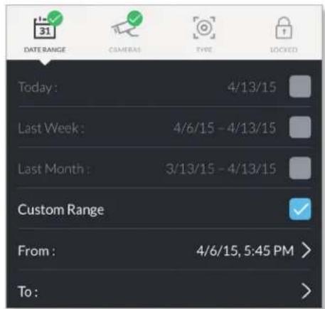
text_image
DATE RANGE CAMERA TYPE LOCKED Today: 4/13/15 Last Week: 4/6/15 - 4/13/15 Last Month: 3/13/15 - 4/13/15 Custom Range From: 4/6/15, 5:45 PM > To:Today Displays a list of all recordings from today.
Last Week Displays a list of recordings from the last seven days.
Last Month Displays a list of recordings from the last month.
Custom Range Allows you to display a list of recordings based on a range of dates and times specified by the user.
• From Select the beginning date and time for your range.
• To Select the ending date and time for your range.
Cameras
Select specific cameras to view in the list of recent recordings. If no specific cameras are selected, then all cameras managed by the NVR will appear in the list.
Type
Allows you to select specific cameras based on their recording mode.
Record on Motion Include cameras that record on motion only.
Always Record Include cameras that record all the time, regardless of motion.
Locked
Locked Filters the view on recent recordings for video clips that are locked and cannot be deleted.
Unlocked Filters the view on recent recordings for video clips that are unlocked.
Appendix A: Mobile App UniFi Video User Guide
Recording Playback Screen
To begin playback of a recently recorded video clip, tap the clip in the Recordings screen list.

text_image
007-02-19:44 Drivingway 00:00/00:14 Duration 13 seconds Camera Driveway Type On Motion Locked NoTap at the top-right corner of the screen to download the video clip to Photos on your mobile device.
Icons below the recording playback screen provide the following controls:
| Icon Name Function | |
| ▷ | Play Tap to play the recording. The icon changes to the Pause icon. |
| || | Pause Tap to pause the recording. The icon changes to the Play icon. |
| ◀◀ | Mute Tap to mute the recording's audio. The icon changes to the Unmute icon. |
| ◀× | Unmute Tap to unmute the recording's audio. The icon changes to the Mute icon. |
Icons at the bottom of the recording playback screen provide the following controls:
| Icon Name Function | |
| [width] | Locked Tap to unlock the video recording. The icon changes to theUnlockedicon. |
| [width] | Unlocked Tap to lock the video recording. The icon changes to theLockedicon. |
| [width] | Delete Tap and confirm to delete the video recording. |
The following information is displayed below the screen:
Duration The duration of the video clip.
Camera The name of the camera that recorded the video clip.
Type The recording criteria: On Motion or Always.
Locked The lock status: Yes (locked) or No (unlocked).
Settings Screen
To access the Settings screen, tap Settings in the overflow menu.
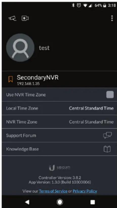
text_image
test SecondaryNVR 192.168.1.35 Use NVR Time Zone Local Time Zone Central Standard Time NVR Time Zone Central Standard Time Support Forum Knowledge Base UBIQUIT Controller Version: 3.8.2 App Version: 1.3.0 (Build 10300006) View our Terms of Service or Privacy PolicyDisconnect from my Ubiquiti Account Tap this option to remove the NVR from your Ubiquiti account. Tap Yes to confirm the deletion.
Notifications Tap this option to enable or disable notifications. The default is enabled.
Use NVR Time Zone Select this option if you want the mobile app to use the NVR's time zone. This does not affect the NVR's time zone.
Local Time Zone This displays the local time zone of your mobile device.
NVR Time Zone This displays the time zone of the NVR.
Support Forum Tap this option to open the UniFi Video Support Forum in a web browser.
Knowledge Base Tap this option to open the UniFi Video Knowledge Base in a web browser.
Appendix B: Standalone Mode
Standalone mode lets you directly access a UniFi Video camera via a web browser, without using the UniFi Video software. Use standalone mode to set up a camera right of the box, and to view a live video feed via RTSP streaming.
Using Standalone Mode

Note: To use standalone mode on a UniFi Video camera, the camera's firmware must be updated to version 3.9. To download the latest firmware for the UniFi Video camera, go to downloads.ubnt.com/
To use standalone mode on a UniFi Video camera:
- Enter https://
- The camera's login screen will appear. Enter your Username and Password (ubnt for both if this is the initial login to the camera). Then click Login.
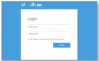
text_image
Login Username Password © the homepage in our website for the Company Database Login- If you want to set up the camera, click Continue and follow the prompts. Otherwise, click Skip.
- The camera's standalone mode window will appear, displaying a live video feed and camera information.

text_image
MNC Q3 Camera Name Camera Name Camera Type Camera Color Camera Color Camera Color Camera Color Camera Color Camera Color Camera Color Camera Color Camera Color Camera Color Camera Color Camera Color Camera Color Camera Color Camera Color Camera Color Camera Color Camera Color Camera Color Camera Color Camera Color Camera Color Camera Color Camera Color Camera Color Camera Color Camera Color Camera Color Camera Color Camera Color Camera Color Camera Color Camera Color Camera ColorBelow the live video display, the window has three tabs: Configure, Network, and System. Edit the settings on each tab as needed.
Configure Tab
The Configure tab displays basic camera settings and allows you to configure certain settings. The top section of the Configure tab provides the following information:

text_image
Name UVC G3 Mode Standalone Enable External Accessory: ✓ Display Camera Name ✓ Display Timestamp ✓ Display Logo Enable Anonymous Snapshot Microphone Volume DISABLE MICROPHONE VERTI-QUALITY RTSP Stream High (1920x1080) Bbit rate FPS Enable RTSP Authentication RTSPURL: rtsp/192.168.10.200:554/50 Width: 1920 Height: 1080 Bitrate: 6000 Hbps FPS: 30 SAVE CHANGES Revert Show RGBName Displays the local device name and a thumbnail image of the camera.
Mode The mode of the camera: UniFi Video or Standalone. The UniFi Video setting indicates that the camera is being managed by UniFi Video. To go into standalone mode, select Standalone and click Save Changes. (If you are prompted to unmanage the camera, do so as described in "Unmanaging a Camera" on page 49.)
UniFi Video Server (Available in UniFi Video mode only.) Displays the IP address of the UniFi video server.
Display Camera Name Used to enable or disable the camera name display in the video feed. Default is Disabled.
Display Timestamp Used to enable or disable the timestamp in the video feed. Default is Enabled.
Display Logo Used to enable or disable the logo display in the video feed. Default is Enabled.
Microphone Volume Move the slider left or right to adjust the microphone volume for recording audio.
Disable Microphone To disable the microphone, click Disable Microphone and then click Continue to confirm.

Note: To re-enable the microphone, you will have to manually reset the camera to factory defaults by pressing its reset button.
Appendix B: Standalone Mode UniFi Video User Guide
Camera Model Displays the model of the camera.
Mode Displays the camera mode: UniFi Video or Standalone.
Connected To Displays the IP address of the server to which the camera is connected.
Uptime Displays the camera's total uptime in days, hours, and minutes.
Video Quality
The Video Quality section is available in Standalone mode only. This section of the Configure tab provides the following information:

text_image
VIDEO QUALITY RTSP Stream High (1920x1080) Bitrate FPS Enable RTSP Authentication RTSP URL: rtsp://192.168.1.15:554/s Width: 1920 Height: 1080 Bitrate: 6000 kbps FPS: 30RTSP Stream Displays the current video resolution of the RTSP stream: High (n x n), Medium (n x n), or Low (n x n).

Note: The displayed resolution for High, Medium, and Low is hardware-dependent. The first number indicates the vertical image height in pixels.
Bitrate Drag the slider control left or right to adjust the RTSP streaming bitrate.
FPS Drag the slider control left or right to adjust the frames per second.
Enable RTSP Authentication Use this option to require a user to authenticate before allowing the user to view an RTSP live stream from the camera. Check the box to enable this option, then enter the Username and Password that will be used for authentication.
RTSP URL Displays the current URL for RTSP streaming.
Width Displays the current width of the RTSP video feed.
Height Displays the current height of the RTSP video feed.
Bitrate Displays the current bitrate of the RTSP video feed.
FPS Displays the current frame rate of the RTSP video feed.
Bottom of Window
The controls displayed at the bottom of the Configure tab are used as follows:
Save Changes Click this button to save changes you have made.
Revert Click this button to cancel any changes you have made and restore the original settings.
Show Video Click this to scroll the window up to the live video feed.
Network Tab
The Network tab displays network-related settings for the camera.
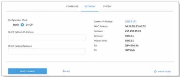
text_image
CONFIGURE NETWORK SYSTEM Configuration Mode Static DHCP DHCP Camera IP Address: 10.0.2.141 MAC Address: 04:18:D6:23:AC:5E Netmask: 235.220.255.0 Gateway: 10.0.2.1 Primary DNS: 10.0.2.1 DHCP Failback Netmask RX: 2B44196 Kb TX: 3853 Mb SAVE CHANGES Revert SHOW VIDEOConfiguration Mode Used to set the camera's IP address configuration mode to Static or DHCP.
DHCP Fallback IP Address Use this to specify the IP address to fall back to if Configuration Mode is set to DHCP and no DHCP server is available.
DHCP Fallback Netmask Use this to specify the IP net mask if Configuration Mode is set to DHCP and no DHCP server is available.
Camera IP Address Displays the camera's IP address.
MAC Address Displays the camera's MAC address.
Netmask Displays the camera's IP net mask.
Gateway Displays the gateway IP address.
Primary DNS Displays the DNS server IP address.
Secondary DNS Displays the secondary DNS server IP address.
Received Displays how much data (in Kb) the camera has received.
Transmitted Displays how much data (in Mb) the camera has sent.
Save Changes Click this button to save changes you have made.
Revert Click this button to cancel any changes you have made and restore the original settings.
Show Video Click this to scroll the window up to the live video feed.
System Tab
The System tab displays system-related information for the camera.

text_image
CONFIGURE NETWORK SYSTEM ACCOUNT Administrator Username ubrt New Password Show Old Password Show Verify New Password Show SAVE CHANGES Revert LANGUAGE Language English SAVE CHANGES Revert TIME & DATE NTP Server pool.ntp.org Timezone SAVE CHANGES Revert FIRMWARE Upload Firmware File Firmware Version: UVC.v3.2.0.50.4334c08.151106.0049 ONCOME MAINTENANCE View Camera Log Download Support File Reset To Defaults Reboot © 2016 Ubiquiti Networks, Inc. All Rights Reserved Privacy Policy Terms of ServiceAccount
The Account section of the System tab provides the following information:
Administrator Username Displays the username for the current user.
Old Password Displays the current password.
New Password To change the password, enter the new password in this field. (Click Show to display the password.)
Verify New Password Re-enter the new password in this field to verify it. (Click Show to display the password.)
Save Changes Click this button to save changes you have made.
Revert Click this button to cancel any changes you have made and restore the original settings.
Language
The Language section of the System tab provides the following information:
Language To change the language used by the UI, click the drop-down menu and select an available language: English, Français, Español, Español (América Latina), Português Brasileiro, Русскǔ, فارسي, 中文 (简体), or 繁體中文. The default is English.
Save Changes Click this button to save any changes you have made.
Revert Click this button to cancel any changes you have made and restore the original settings.
Time and Date
This section is available in Standalone mode only.
NTP Server Displays the IP address or URL of the Network Time Procotol (NTP) server from which the camera obtains its system time.
Timezone Displays the camera's time zone.
Firmware
The Firmware section of the System tab contains the following options and information:
Upload Firmware File Displays the name of the firmware file that you have selected for upload.
Choose Click this button to select a firmware file for upload to the camera.
Firmware Version Displays the version of the firmware that is currently installed in the camera.
Maintenance
The Maintenance section of the System tab provides the following information:
View Camera Log Click this to display the camera log. When you are finished viewing, click Cancel to close the window or Save to save a local copy.

text_image
VIEW CAMERA LOG 2018-02-24 15:12:12 502415,712 P7 netd[948]: Enquaging task 'NetworkStatus' (type): 0, id: 36 2018-02-24 15:12:12 502415,719 P7 netd[948]: onTaskFinished(); 'NetworkStatus' (type): 0, id: 2018-02-24 15:12:42 502445,726 P7 netd[948]: Enquaging task 'NetworkStatus' (type): 0, id: 56 2018-02-24 15:13:42 502445,736 P7 netd[948]: onTaskFinished(); 'NetworkStatus' (type): 0, id: 2018-02-24 15:13:12 502475,719 P7 netd[948]: Enquaging task 'NetworkStatus' (type): 0, id: 57 2018-02-24 15:13:12 502475,722 P7 netd[948]: onTaskFinished(); 'NetworkStatus' (type): 0, id: 2018-02-24 15:13:42 502505,704 P7 netd[948]: Enquaging task 'NetworkStatus' (type): 0, id: 57 2018-02-24 15:13:42 502505,710 P7 netd[948]: onTaskFinished(); 'NetworkStatus' (type): 0, id: 2018-02-24 15:14:12 502535,708 P7 netd[948]: Enquaging task 'NetworkStatus' (type): 0, id: 57 2018-02-24 15:14:12 502535,715 P7 netd[948]: onTaskFinished(); 'NetworkStatus' (type): 0, id: 2018-02-24 15:14:20 502564,018 P6 analytics[943]: Sending event (113) start. triggers [0-21 2018-02-24 15:14:28 502562,151 P6 analytics[943]: Sending event (113) stop. triggers [0-36] 2018-02-24 15:14:42 502565,707 P7 netd[948]: Enquaging task 'NetworkStatus' (type): 0, id: 57 2018-02-24 15:14:42 502565,713 P7 netd[948]: onTaskFinished(); 'NetworkStatus' (type): 0, id: 2018-02-24 15:15:12 502595,733 P7 netd[948]: Enquaging task 'NetworkStatus' (type): 0, id: 57 2018-02-24 15:15:12 502590,737 P7 netd[948]: onTaskFinished(); 'NetworkStatus' (type): 0, id: 2018-02-24 15:15:42 502626,735 P7 netd[948]: Enquaging task 'NetworkStatus' (type): 0, id: 57 2018-02-24 15:15:42 502626,735 P7 netd[948]: onTaskFinished(); 'NetworkStatus' (type): 0, id: 2018-02-24 15:16:12 502635,736 P7 netd[948]: Enquaging task 'NetworkStatus' (type): 0, id: 57 2018-02-24 15:16:12 502639,739 P7 netd[948]: onTaskFinished(); 'NetworkStatus' (type): 0, id: 2018-02-24 15:16:42 502685,765 P7 netd[948]: Enquaging task 'NetworkStatus' (type): 0, id: 57 2018-02-24 15:16:42 502686,794 P7 netd[948]: onTaskFinished(); 'NetworkStatus' (type): 0, id: 2018-02-24 15:17:12 502715,739 P7 netd[948]: Enquaging task 'NetworkStatus' (type): 0, id: 57 2018-03-24 15x:17:12 502715,736 P7 netd[948]: onTaskFinished(); 'NetworkStatus' (type): 0, id:Download Support File Click this to download the support file.
Reset To Defaults Click this to reset the camera to its factory default settings.
Reboot Click this to reboot the camera.
Show Video Click this to scroll back up to the top the window to display the live video feed.
Configuring the Camera
When the camera is in standalone mode, the top right corner of the live video feed display has two icons:
- click this icon to toggle the live video screen between normal size and full-screen display.
- Click this icon to display the drop-down menu that allows you to perform the following camera functions:

natural_image
Vertical toolbar with icons representing weather, lighting, and refresh (no text or symbols)- Brightness adjust the brightness of the live view image by dragging the slider control to the left or right.
- Contrast ☐ adjust the contrast of the live view image by dragging the slider control to the left or right.
- Hue Adjust the hue of the live view image by dragging the slider control to the left or right.
- Saturation adjust the saturation of the live view image by dragging the slider control to the left or right.
- Denoise adjust the noise level of the live view image by dragging the slider control to the left or right.
- Sharpness adjust the sharpness of the live view image by dragging the slider control to the left or right.
- WDR Adjust the WDR (Wide Dynamic Range) sensitivity of the live view image by dragging the slider control to the left or right. WDR helps create better image and video detail in frames that contain both light and dark areas that would otherwise be over- or underexposed.
-
AE Mode ☒ choose AE (Auto Exposure) mode for the live view images by selecting Normal, Anti-Flicker for 60 Hz light, or Anti-Flicker for 50 Hz light from the dropdown menu. The default is Normal.
-
Flip Reverse the image vertically (flip upside down) by selecting Flip from the drop-down menu, or restore the normal view by selecting Normal from the drop-down menu. The default is Normal.
- Mirror Reverse the image horizontally (mirror image) by selecting Mirror from the drop-down menu, or restore the normal view by selecting Normal from the drop-down menu. The default is Normal.
- IR Mode the infrared filter can be changed for the live view image by selecting On or Off from the dropdown menu. The default setting is Auto.
- Zoom adjust the optical zoom (if equipped) from 1x up to 3x.
- Focus adjust the focus mechanism (if equipped).
Standalone Mode from UniFi Video
You can also enter standalone mode on a camera from within the UniFi Video software.
Entering Standalone Mode
To enter standalone mode on a camera within UniFi Video:
- On the Cameras tab, click the camera's IP address in the Host column.
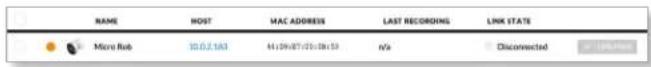
text_image
NAME HOST MAC ADDRESS LAST RECORDING LINK STATE Micro Rob 10.0.2.163 41/09/07/20:28:53 n/a Disconnected- The camera's login screen will appear. Enter your Username and Password. Then click Login.

text_image
Login Username Password • Be loading to any user in the Optical Services. OK- If you want to set up the camera, click Continue and follow the prompts. Otherwise, click Skip.
- The camera's standalone mode window will appear, displaying a live video feed and camera information.

text_image
U DRPT 300 C:\Users\DRPT\300\1.2.1.1\1.2.1.2\1.2.1.3\1.2.1.4\1.2.1.5\1.2.1.6\1.2.1.7\1.2.1.8\1.2.1.9\1.2.1.10\1.2.1.11\1.2.1.12\1.2.1.13\1.2.1.14\1.2.1.15\1.2.1.16\1.2.1.17\1.2.1.18\1.2.1.19\1.2.1.20\1.2.1.21\1.2.1.22\1.2.1.23\1.2.1.24\1.2.1.25\1.2.1.26\1.2.1.27\1.2.1.28\1.2.1.29\1.2.1.30\1.2.1.31\1.2.1.32\1.2.1.33\1.2.1.34\1.2.1.35\1.2.1.36\1.2.1.37\1.2.1.38\1.2.1.39\1.2.1.40\1.2.1.41\1.2.1.42\1.2.1.43\1.2.1.44\1.2.1.45\1.2.1.46\1.2.1.47\1.2.1.48\1.2.1.49\1.2.1.50\1.2.1.51\1.2.1.52\1.2.1.53\1.2.1.54\1.2.1.55\1.2.1.56\1.2.1.57\1.2.1.58\1.2.1.59\1.2.1.\nDrain Camera\nDrive Computer\nDrive Trimming\nDrive Log\nDrive Log/Trimming (log/Trimming)\nPharmature Display\nControl Panel\nControl Panel\nControl Panel\nControl Panel\nControl Panel\nControl Panel\nControl Panel\nControl Panel\nControl Panel\nControl Panel\nControl Panel\nControl Panel\nControl Panel\nControl Panel\nControl Panel\nControl Panel\nControl Panel\nControl Panel\nControl Panel\nControl Panel\nControl Panel\nControl Panel\nControl Panel\nControl Panel\nControl Panel\nControl Panel\nControl Panel\nControl Panel\nControl Panel\nControl Panel\nControl Panel\nControl Panel\nControl Panel\nControl Panel- If the Mode field is set to UniFi Video, click Standalone and click Save Changes. (If you are prompted to unmanage the camera, do so as described in "Unmanaging a Camera" on page 49.)
You will now have direct access to the camera through standalone mode.
Unmanaging a Camera
To access a camera from UniFi Video using standalone mode, the camera must be unmanaged.
To check if a camera is managed or unmanaged:
- Go to the Cameras tab.
- Click Managed to display the list of managed cameras.
- If the camera appears in the list, the camera is managed. If not, the camera is unmanaged.
To unmanage a managed camera:
- Go to the Cameras tab.
- Click Managed to display the list of managed cameras.
- Select the camera from the list to display its details window.
-
Select the Manage tab on the details window.
-
Click Unmanage.
-
If you want to keep the camera's recordings, click Keep My Recordings. To delete the camera's recordings (except locked recordings), click Remove Everything.
UniFi Video User Guide
Appendix C: Contact Information
Ubiquiti Networks Support
Ubiquiti Support Engineers are located around the world and are dedicated to helping customers resolve software, hardware compatibility, or field issues as quickly as possible. We strive to respond to support inquiries within a 24-hour period.
Ubiquiti Networks, Inc.
685 Third Avenue, 27th Floor
New York, NY 10017
USA
Online Resources
Website: www.ubnt.com
Support: ubnt.link/UniFi-Video-Support
Community: https://community.ubnt.com/t5/UniFi-Video/bd-p/airVision_board
Downloads: www.ubnt.com/download/unifi-video
AJAI010518

natural_image
Abstract logo design featuring a stylized letter 'U' with blue and gray curved elements (no text or symbols)www.ubnt.com