
7833 - Car alarm GEMINI - Free user manual and instructions
Find the device manual for free 7833 GEMINI in PDF.


| Product Type | Car Alarm System |
| Brand | Gemini |
| Model | 7833 |
| Power Supply | 12V DC (vehicle battery) |
| Control Unit Dimensions | 80 x 60 x 25 mm |
| Weight | 200 g |
| Remote Control Range | Up to 100 meters |
| Shock Sensor | Adjustable dual-zone |
| Siren Output | 120 dB |
| Engine Immobilizer | Yes |
| Remote Keyless Entry | Yes |
| Panic Function | Yes |
| Anti-Hijack Mode | Yes |
| Override Switch | Valet mode with key |
| Maintenance | Replace remote battery annually |
| Cleaning | Wipe control unit with dry cloth |
| Safety Precautions | Disconnect battery before installation |
| Spare Parts | Remote controls, siren, wiring harness |
| Repairability | Requires professional installation |
| Warranty | 1 year |
Frequently Asked Questions - 7833 GEMINI
User questions about 7833 GEMINI
0 question about this device. Answer the ones you know or ask your own.
Ask a new question about this device
Download the instructions for your Car alarm in PDF format for free! Find your manual 7833 - GEMINI and take your electronic device back in hand. On this page are published all the documents necessary for the use of your device. 7833 by GEMINI.
USER MANUAL 7833 GEMINI
7833
7832
INSTALLER AND USER MANUAL
UK
CE
For all EU Countries

AC XXXX Rev. 04 - 08/07
UK
1.0 - CONTENTS
1.0 - CONTENTS.... PAGE 02
2.0 - GENERAL NOTE FOR INSTALLATION...... PAGE 02
3.0 - FUNCTIONS...... PAGE 03
4.0 - OPERATING DESCRIPTION...... PAGE 03
4.1 - Complete system arming..... PAGE 03
4.2 - System arming with sensor exclusion...... PAGE 03
4.3 - Passive arming..... PAGE 04
4.4 - Arming inhibit time.... PAGE 04
4.5 - System armed.... PAGE 04
4.6 - Alarm, inhibit time and alarm cycles.... PAGE 04
4.7 - System disarming.... PAGE 04
4.8 - Emergency disarming by electronic key.... PAGE 04
4.9 - Alarm memory...... PAGE 05
5.0 - ELECTRICAL CONNECTIONS...... PAGE 05
6.0 - CONNECTOR TABLE...... PAGE 06
7.0 - CONNECTION FOR TURN SIGNALS ACTIVATION PAGE 06
8.0 - COMPLETE ELECTRIC DIAGRAM...... PAGE 07
9.0 - SYSTEM PROGRAMMING...... PAGE 08
9.1 - Acoustic signalling...... PAGE 08
9.2 - Impulse optic signalling...... PAGE 08
9.3 - Optic signalling by arming/disarming...... PAGE 08
9.4 - System passive arming.... PAGE 08
9.5 - Negative comfort.... PAGE 08
9.6 - Satellite system activation.... PAGE 08
10.0 - SYSTEM PROGRAMMING EXAMPLE ...... PAGE 09
11.0 - VEHICLE CODE PROGRAMMING...... PAGE 10
12.0 - VEHICLE CODE PROGRAMMING EXAMPLE...... PAGE 11
13.0 - ADD NEW ELECTRONIC KEY...... PAGE 12
14.0 - WASTE ELECTRICAL AND ELECTRONIC EQUIPMENT (WEE) DIRECTIVE... PAGE 12
15.0 - WARRANTY CONDITIONS...... PAGE 13
16.0-TECHNICAL DATA....PAGE 13
2.0 - GENERAL NOTE FOR INSTALLATION
Dear installer, this manual has been written based on a complete system, therefore some functions, electrical connections and other can be present in one alarm version and not in another.
In order to avoid repetitions in the manual, before installing the alarm, verify its version and then follow the suitable instructions.
Furthermore, in order to carry out correctly the various procedures required, please VERIFY VERY CAREFULLY ALL THE ELECTRICAL CONNECTIONS, IN PARTICULAR THE CONNECTIONS
LISTED BELOW:
Device power supply (positive and ground).
Positive under key (+15/54)
Bonnet switch (if not on CAN-BUS line).
CAN-BUS line.
GEMINI 7832: same as 7833 without self-powered battery.
3.0 - FUNCTIONS
System arming and disarming by the vehicle original remote.
Acoustic arming/disarming signaling (excludable by programming).
Optical signalling (programmabili per inserimento e disinserimento se non presenti sul veicolo).
Perimetric protection.
Volumetric protection (excludable by arming).
Electrical engine immobiliser.
Negative output for additional siren.
Comfort negative output (about 20 seconds) or satellite system control.
LED memory.
Multifunction electronic key (random rolling code, 4.2 milliard of different codes).
4.0 - OPERATING DESCRIPTION
Furthermore, in order to indicate to the installer and to the user some particular functions or connections, an icon symbology has been used, which is briefly described below:

Indications useful for the installer.
This icon indicates to the installer a diversified operating, according to the connection and the programming of the system or it simply provides indications useful for the installation.

Indications useful for the user.
The user with indications for a diversified use of the system or it simply provides indications useful for the use.
4.1 - COMPLETE SYSTEM ARMING
Press the lock button on the original radio control of the vehicle or insert the electronic key into the specific receptacle.
Arming will be indicated by two short acoustic signals and by a number of optical signals (default vehicles manufacturer setting).

In case the vehicle has not optical signals when is closed, it is possible to activate these signals by programming. In this case, when the system is armed, two optical signals will be emitted
4.2 - SYSTEM ARMING WITH SENSOR EXCLUSION
This function allows the user to arm the system, with volumetric protection excluded.
To active this function, the system must be disarmed and the ignition switched in "OFF" position and than proceed as follows:
Turn the vehicle ignition key in "ON" position and wait for one second the status LED switches off (the drivers door can be open or close at this point).
Introduce the electronic key into the receptacle; he status LED will flash for one second and two short acoustic signals will indicate the exclusion of volumetric sensors
Turn the vehicle ignition key in "OFF" position.

When an immediate re-arming of volumetric sensors is required, switch the vehicle ignition key in "ON" and "OFF" position.
Press the lock button of the vehicle's original radio control or insert the electronic key into the receptacle.
^9 Two acoustic signals and the number of optical signals that has been programmed by the car's manufacturer will indicate that the system has been armed.

Sensor exclusion is bound to the single arming cycle.
4.3 - PASSIVE ARMING
After the programming, the alarm is set to be passively armed, about 60" after the vehicle switching off.

In case of alarm passive arming, internal sensors and comfort output will be excluded (automatic window closing).
Moreover, the vehicle's door opening during the 60" before the passive arming, does not inhibit activation.
4.4 - ARMING INHIBIT TIME
The inhibit arming time lasts for approximately 40 seconds and is indicated by a illuminated status LED.
4.5 - SYSTEM ARMED
After the inhibit time (about 40 sec.), the system is "armed" and it is ready to detect any theft attempt. When the system fully armed, the LED flashes.
After disarming the system, any occurred attempt will be indicated by the alarm with visual/acoustic signaling (see relative paragraph).
4.6 - ALARM, INHIBIT TIME ANDALARM CYCLES
As mentioned before, the alarm will indicate any theft attempt by optical/acoustic signals, depending on the system.
After the alarm has been triggered, before another alarm cause, there are 5 second of "neutral time". The alarm signalling has 7 cycles of 30" each for input and arming cycles. The ignition key (+15/54) and the cut wire alarm signaling have no cycle limitation.
4.7 - SYSTEM DISARMING
Press the unlock button on the original radio control of the vehicle.
Disarming is indicated by three short acoustic signals and by a number of optical signals, which have been programmed by the vehicles manufacturer.
If an alarm condition has occurred, it will be signalled by five quick acoustic signals. See relative paragraphs (4.9) for possible causes and signaling.

In case the vehicle has not optical signals when is opened, it is possible to activate these signals by programming.
In this case, when the system is disarmed, three optical signals will be emitted
4.8 - EMERGENCY DISARMING BY ELECTRONIC KEY
This kind of disarming has been conceived as an "EMERGENCY DISARMING" and "TOTAL DISARMING".
When placing the electronic key into the specific receptable, the alarm system disarms and switches OFF.
It will be not re-arm when the vehicle radio control is used.
PAGE 04 PAGE 05

It is possible to carry out the complete disarming procedure only when the system is armed, during one alarm cycle or during the neutral time between two alarm cycle but not during the arming neutral time.
To restore normal operation, it is necessary to put one time the electronic key into the specific receptacle and again during the arming inhibit time (LED lighted on).
4.9 - ALARM MEMORY
In case of five acoustic signals occurring at the alarm disarming, thanks to the LED's memory, it is possible to identify the cause which has generated the last alarm condition.
To do this, turn the ignition key in "ON" position and look at the vehicle installed LED. The LED will start to blinks, shown the last alarm condition.
The cause of the alarm will indicate for 5 times.
This indication can be interrupted by turning the ignition "OFF".
The possible alarm trigger signaling are indicated in the table reported below.
| LED SIGNALLING CAUSE OF ALARM | ALARM CYCLE NUMBER | |
| *** | Doors opening | 7 |
| ***** | Start attempt (+15/54) | Infinite |
| ***** | Boot/bonnet opening | 7 |
| ***** | Cut wires | Infinite |
| ***** | Volumetric sensors | 7 |
| LED OFF (2 seconds) * LED ON (1second) | ||
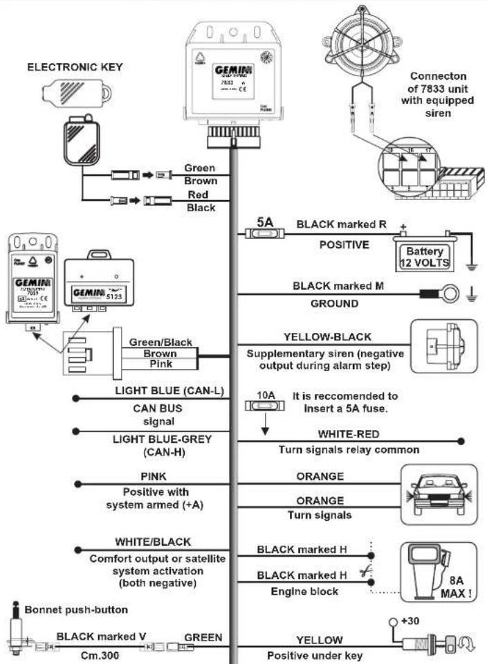
5.0 - ELECTRICAL CONNECTIONS
Connect the supply power positive of the system to the vehicle battery pole or to one of its derivations.
Connect the supply power negative of the system to the vehicle's original earth point.
Connect the GREEN wire of the alarm wiring harness to the bonnet switch. If the signal is present in the CAN-BUS line, leave this wire available
Connect the GREEN/BLACK wire of the system to the GREN/BLACK wire of the ultrasonic sensor or hyperfrequency sensor.
^a Verify the use of ORANGE and WHITE/RED wires, according to the alarm programming (see installation specifications).
^2 Verify carefully the wires of CAN-BUS line in the vehicle on which the installation is to be carried out.
Follow with GREAT ATTENTION the instructions for CAN-BUS line connection; do not invert CAN-H and CAN-L wires, otherwise the system will not work.

Before carrying out all electrical connections, disconnect the negative battery terminal and re-connect again after completion.

Available diagrams for specific vehicles can be downloaded on the web-site www.gemini-alarm.com (private area).
6.0 - CONNECTOR TABLE
| WIRE POSITION AND FUNCTION | WIRE COLOUR |
| 4 - Ground | BLACK marked M |
| 5 - Positive | BLACK marked R |
| 11 - Engine immobiliser | BLACK marked H |
| 12 - Engine immobiliser | BLACK marked H |
| 20 - Positive under key | YELLOW |
| 7 - Bonnet switch negative input(if not on CAN BUS line) | GREEN |
| 1 - Positive with system armed (+A) | PINK |
| 9 - Additional siren negative control | YELLOW/BLACK |
| 6 - Comfort output or satellite system activation output (both negative) | WHITE/BLACK |
| 15 - Turn signals positive/negative common | WHITE/RED |
| 14 - Turn signals positive/negative output | ORANGE |
| 16 - Turn signals positive/negative output | ORANGE |
| 2 - CAN BUS line (CAN-L) | LIGHT BLUE |
| 3 - CAN BUS line (CAN-H) | LIGHT BLUE/GREY |

In the alarm wiring two two-way connectors and a four-way connectors are present, whose functions are described below.
BLACK 2-way plug holder connector, RED and BLACK wires: connection of the signalling LED.
BLACK 2-way female holder connector, GREEN and BROWN wires: connection of the electronic key receptacle.
BLACK 4-way female holder connector, GREEN/BLACK, BROWN and PINK wires: connection of volumetric sensors (hyperfrequency or ultrasonic module).
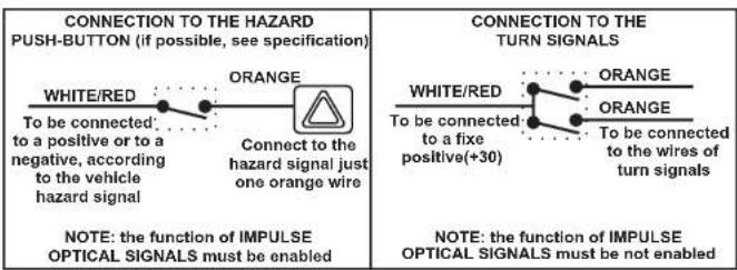
7.0- CONNECTION FOR TURN SIGNALS ACTIVATION
Connection and programming must be made according to the turn signals connection mode (standard or hazard), as indicated in the installation sheets.
The "standard configuration" module is set for connections as shown in the first design.
To modify configuration from "standard" to "impulse", please follow instructions given in the programming paragraph and then proceed with wiring connections as shown in the second design.
8.0 - COMPLETE ELECTRIC DIAGRAM
flowchart
graph TD
    A["ELECTRONIC KEY"] --> B["Green Brown Red Black"]
    B --> C["5A BLACK marked R"]
    C --> D["Battery 12 VOLTS"]
    D --> E["5A"]
    E --> F["5A"]
    F --> G["5A"]
    G --> H["5A"]
    H --> I["5A"]
    I --> J["5A"]
    J --> K["5A"]
    K --> L["5A"]
    L --> M["5A"]
    M --> N["5A"]
    N --> O["5A"]
    O --> P["5A"]
    P --> Q["5A"]
    Q --> R["5A"]
    R --> S["5A"]
    S --> T["5A"]
    T --> U["5A"]
    U --> V["5A"]
    V --> W["5A"]
    W --> X["5A"]
    X --> Y["5A"]
    Y --> Z["5A"]
    Z --> AA["5A"]
    AA --> AB["5A"]
    AB --> AC["5A"]
    AC --> AD["5A"]
    AD --> AE["5A"]
    AE --> AF["5A"]
    AF --> AG["5A"]
    AG --> AH["5A"]
    AH --> AI["5A"]
    AI --> AJ["5A"]
    AJ --> AK["5A"]
    AK --> AL["5A"]
    AL --> AM["5A"]
    AM --> AN["5A"]
    AN --> AO["5A"]
    AO --> AP["5A"]
    AP --> AQ["5A"]
    AQ --> AR["5A"]
    AR --> AS["5A"]
    AS --> AT["5A"]
    AT --> AU["5A"]
    AU --> AV["5A"]
    AV --> AW["5A"]
    AW --> AX["5A"]
    AX --> AY["5A"]
9.0 - PROGRAMMING THE ALARM SYSTEM
The table given below is applied to the alarm programmed in "standard configuration".
| FUNCTION STATE | |
| Acoustic signalling | Enabled |
| Impulse optical signals | Disabled |
| Optical signals by arming/disarming | Disabled |
| Alarm passive arming | Disabled |
| Management “Negative comfort” or “Satellite system activation” | Satellite system activation |
Power supply interruption will not modify the programming carried out..

Entering the programming procedure resets the functions to the default setting (preset by Gemini).
The procedure must be carried out completely
Indeed, when changing the position of the ingition key, the function is confirmed, the next step is activated and so on till the end of programming procedure.
In the example in the next page, programming instructions are given.
According to the programming procedure and the vehicle's operation, to connect the turn signals, please follow the relative diagram.
Programmable functions are briefly described below.
9.1 - ACOUSTIC SIGNALLING
2 short acoustic signals when arming, 3 short acoustic signals when disarming and 5 short acoustic signals when disarming with alarm memory.
9.2 - IMPULSE OPTIC SIGNALS
Function to be activated in particular vehicles, where connections are made directly to the hazard switch.
Activation of this function excludes automatically the next function.
9.3 - OPTIC SIGNALLING BY ARMING/DISARMING
This function can be activated only in vehicles which do not have opening/closing optical signals
9.4 - SYSTEM PASSIVE ARMING
The alarm is armed about 60 seconds after the engine turning off (positive under key missing) When the alarm is automatically armed the activation of output “+A” (positive with the alarm being armed) and of comfort are not foreseen
9.5 - NEGATIVE COMFORT
This is a function allowing to close the windows during the alarm arming phases. Please keep in mind that the function is excluded, if the sensors are not activated (paragraph 4.2) or the alarm is passively armed (paragraph 4.3).
9.6 - SATELLITE SYSTEM ACTIVATION
This is a function allowing to activate the comfort output, for the whole time of alarm arming

When you are programming the output for satellite module activation, the connection of the same wire to the vehicle's comfort is not suggested.
PAGE 08 PAGE 09
10.0 - EXAMPLE OF ALARM PROGRAMMING
For better understanding programming step, we describe below an example of the procedure to modify the programmable functions.
As mentioned before, the positive under key confirms the functions, while the electronic key modify them.
With the alarm being disarmed, turn the vehicle ignition key in "ON" position "ON".
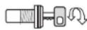
ON
The LED will flash for about one second.
During this period insert the electronic key into the specific receptacle.

Starting of programming procedure is indicated by one high tone and one low tone acoustic signal.


OFF-ON
In order to keep the unchanged setting, turn the ignition "OFF" and then back "ON". An acute acoustic signal will confirm the operation.

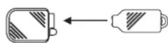
To change the operating state, put once the electronic key in the specific receptacle. An acute acoustic signal will confirm the operation.

In both cases, the alarm will pass at the next function.
Repeat the operation for the other functions.
When the fifth function has been programmed, either the electronic key is inserted into the receptacle, or the ignition key is turned, in addition to the programmed function tonality, two acoustic signals are emitted: one high tone and the other low tone.
These last two acoustic signals indicate the end of the programming procedure.
11.0 - VEHICLE CODE PROGRAMMING
In presence of a CAN-BUS line, the alarm needs a configuration depending on the vehicles model and make.
The alarm is supplied without any programming, since Gemini does not know the vehicle on which the module will be installed.
For this reason, programming has to be carried out during installation.
Indeed, even in the same vehicle's brand, operating differences are possible, according to the model (es. Coupè o station wagon).

The vehicle's codes are given in the supplementary leaflet included in the alarm packaging (the codes are updated at the packaging time).
Please refer to our web site "www.gemini-alarm.com" for updating information (private area).
To program the vehicle code, proceed as follows.
When installation is complete, connect the 20-way wiring harness connector to the 20-way system connector.
Push and hold the button located on the front of the alarm control unit until the LED is switches on.
Release the button the LED will switch off.
After a short pause, the LED will start flashing.
Count the number of LED flashes until it corresponds to the first number of the code, then press the button on the front of the control unit.
After a short pause, the led will start flashing again.
Count the number of LED flashes until it corresponds to the second number of the code, then press the button on the front of the control unit.
After a short pause, the led will start flashing again.
Count the number of LED flashes until it corresponds to the third number of the code, then press the button on the front of the control unit.
At the end of programming procedure, the alarm will «repeat» the entered code, by flashing the LED.
/ Verify the alarm system operation using the original radio control lock button of the vehicle.
If the entered code is correct and corresponds to the vehicle, the alarm will operate correctly.
If the code has been entered incorrectly repeat the procedure.
The table below refers the values corresponding to the LED flashes that have been entered in the alarm.
| FLASHFLASH | VALUEVALUE | ||
| First flash | Number value - 1 - | Sixth flash | Number value - 6 - |
| Second flash | Number value - 2 - | Seventh flash | Number value - 7 - |
| Third flash | Number value - 3 - | Eighth flash | Number value - 8 - |
| Fourth flash | Number value - 4 - | Ninth flash | Number value - 9 - |
| Fifth flash | Number value - 5 - | Tenth flash | Number value - 0 - |
12.0 - EXAMPLE OF ALARM MODULE CODE PROGRAMMING
For better understanding of coding, described below the procedure for entering the vehicle code. In the given example, the code 1-0-3 corresponds hypothetically to the cariAT XXXXX".
Connect the 20-way wiring harness connector to the 20-way system connector. Push and hold the button shown in figure, until the LED is switches on.

Release the button the LED switches off.

After 3/4 second pause the LED will start with the first sequence of flashes. Push the button at firts LED flashing, corresponding to value "1".

After 3/4 second pause the LED will start with the second sequence of flashes. Push the button at tenth LED flashing, corresponding to value "0".

After 3/4 second pause the LED will start with the third sequence of flashes. Push the button at third LED flashing, corresponding to value "3".

When the last digit has been entered, the alarm will "repeat" the entered code.



Press the vehicle radio control lock/unlock buttons to verify the alarm operation. Eventually disconnect the 20-ways connector and reconnect it after few seconds.
13.0 - ADD NEW ELECTRONIC KEY
The alarm can memorise up to a maximum of 4 electronic keys.
Programming is directly depending on the connection of GREEN wire which protects the grounded hood.
If this connection was not required, since bonnet opening is detected by CAN-BUS signals, before starting new electronic key programming, connect this wire to earth
Than proceed as described below
With the system disarmed, turn the vehicle ignition key in "ON" position.
Turn the vehicle ignition key in "OFF" position.
Re-turn the ignition key to "ON" for three consecutive times (ignition key to "ON" and "OFF"), within the maximum time of four seconds.
After the fourth commutation, let the ignition key to "ON" position.
The alarm will indicate the procedure starting of new electronic key learning by two acoustic signals, one acute tone and the other low tone, and two long flashes of the status LED.
Introduce the electronic key to be self learned in the specific receptacle.
The alarm will indicate the new electronic key learning by one status LED flash and an acoustic signal.
Repeat the same operation for all the keys.
Turn the ignition "OFF" and close the bonnet (or remove the Green wire from the negative).
The procedure completion will be indicated by one long acoustic signal and one flash of the status LED.

Programming a fifth device will delete the first device programmed into the alarm system memory.
14.0 - WASTE ELECTRICAL AND ELECTRONIC EQUIPMENT (WEEE) DIRECTIVE
In the European Union, this lable indicated that this product should not be disposed of with household waste. It should be deposited at an appropriate facility to enable recovery and recycling (directive 2002/95/CE, 2002/96/CE and 2003/108/CE).
For information on how to recycle this product responsibly in your Country, please visit the web-site: Www.eur-lex.europa.eu

natural_image
Simple line drawing of a trash bin with crossed lines indicating no waste or plastic (no text or symbols)
APPROPRIATE CONTAINER ONLY
PAGE 12 PAGE 13
15.0 - WARRANTY CONDITIONS
This apparatus is guaranteed against all defects of fabrications for a period of 24 month from the installation date shown on this warranty coupon, taking into consideration the 1999/44/CE. Therefore, you are kindly requested to fill entirely the guarantee certificate included in this booklet and to NOT REMOVE the guarantee label from the device.
Missing or tearing of this label, missing of one part of guarantee certificate or missing of the enclosed sale document, will invalidate the guarantee.
The guarantee is valid exclusively to Gemini Technologies S.p.A.Authorized Service Centers. The manufacturer will decline any responsibility for any eventual malfunctions of the device, or electrical plant damages of the vehicle, due to improper installation, use or tampering. This alarm has exclusively a deterrent function against eventual thefts.

Any type of modification or addition not expressly indicated on the installer manual or authorized by Gemini Technologies S.p.A., will invalidate automatically the installation certificate and product warranty.
16.0 - TECHNICAL DATA
| Nominal supply voltage | 12 Vdc |
| Nominal supply voltage range | From 10 to 15Vdc |
| Current absorption @ 12Vdc | 10mA |
| Working range temperature | From -30°C to +70°C |
| Turn signals output current capacity | 8A at 20°C |
| Engine immobilisation current capacity | 8A at 20°C |
| Alarm cycle duration | 30 sec. |
| Maximum positive current output when armed (+A) | 800 mA |
| Additional siren output current capacity | 5A |
- INSTALLER AND USER MANUAL
- UK
- - CONTENTS
- - GENERAL NOTE FOR INSTALLATION
- LISTED BELOW:
- - FUNCTIONS
- - OPERATING DESCRIPTION
- Indications useful for the installer.
- Indications useful for the user.
- - COMPLETE SYSTEM ARMING
- - SYSTEM ARMING WITH SENSOR EXCLUSION
- - PASSIVE ARMING
- - ARMING INHIBIT TIME
- - SYSTEM ARMED
- - ALARM, INHIBIT TIME ANDALARM CYCLES
- - SYSTEM DISARMING
- - EMERGENCY DISARMING BY ELECTRONIC KEY
- - ALARM MEMORY
- - ELECTRICAL CONNECTIONS
- 7.0- CONNECTION FOR TURN SIGNALS ACTIVATION
- - PROGRAMMING THE ALARM SYSTEM
- - ACOUSTIC SIGNALLING
- - IMPULSE OPTIC SIGNALS
- - OPTIC SIGNALLING BY ARMING/DISARMING
- - SYSTEM PASSIVE ARMING
- - NEGATIVE COMFORT
- - SATELLITE SYSTEM ACTIVATION
- - EXAMPLE OF ALARM PROGRAMMING
- - VEHICLE CODE PROGRAMMING
- - EXAMPLE OF ALARM MODULE CODE PROGRAMMING
- - ADD NEW ELECTRONIC KEY
- - WASTE ELECTRICAL AND ELECTRONIC EQUIPMENT (WEEE) DIRECTIVE
- - WARRANTY CONDITIONS
Brand : GEMINI
Model : 7833
Category : Car alarm