
7090 - Car alarm GEMINI - Free user manual and instructions
Find the device manual for free 7090 GEMINI in PDF.


| Type de produit | Alarme auto avec télécommande |
| Marque | Gemini |
| Modèle | 7090 |
| Alimentation | 10.5 - 14.5 V DC |
| Température de fonctionnement | -30°C à +85°C |
| Courant max (alarme désarmée) | 15 mA (avec sirène auto-alimentée) |
| Fréquence des télécommandes | 433.92 MHz |
| Capacité des relais (clignotants, immobilisation, klaxon, verrouillage central) | 10 A DC |
| Capacité sortie confort positif/négatif | 100 mA |
| Accessoires inclus | 2 télécommandes (art. 7208E), 2 clés électroniques (CDE2), sirène (modèles variables) |
| Fonctions principales | Verrouillage/déverrouillage à distance, immobilisation moteur, protection périmétrique et volumétrique, ouverture de coffre, fonction panique, mémoire des déclenchements |
| Programmation utilisateur | 8 fonctions programmables via télécommande (son continu/alterné, signal sonore, ouverture coffre, etc.) |
| Apprentissage des télécommandes | Jusqu'à 8 dispositifs (télécommandes et clés) |
| Mode garage | Désactive temporairement l'immobilisation passive (20 démarrages) |
| Position garage | Exclut l'immobilisation moteur pour entretien |
| Type de sirène compatible | Sirène auto-alimentée (Gemini 7025, 7125) ou sirène supplémentaire |
| Montage | Installation professionnelle recommandée, schémas de câblage fournis |
| Entretien | Vérifier les connexions, remplacer les piles des télécommandes (CR1616) |
| Garantie | 12 mois contre défauts de fabrication |
Frequently Asked Questions - 7090 GEMINI
User questions about 7090 GEMINI
0 question about this device. Answer the ones you know or ask your own.
Ask a new question about this device
Download the instructions for your Car alarm in PDF format for free! Find your manual 7090 - GEMINI and take your electronic device back in hand. On this page are published all the documents necessary for the use of your device. 7090 by GEMINI.
USER MANUAL 7090 GEMINI
The undersigned,qualified installer,attests to have personally fitted the here described Vehicle Security system following the manufacturer instructions.
CERTIFICAT D'INSTALLATION
natural_image
Blank white image with no visible content, text, or symbolsSold on : Venduto Vendu le Verkauft Vendido Vendido
Type of product : Tipo di prodotto : Produktartikel : Type de dispositif Dispositivo ciclo : Tipo de dispositiv
□ 7090
No formal text given is obtained to prepare the 100% psychology paper.


by GEMINI TRADING S.r.l. Via Luigi Galvani 12 21020 Bodio Lomnago (VA) Italia Tel. +39 0332 943211 - Fax +39 0332 948080
E-mail: info@gemini-alarm.com
7090

UK
GEMINI
AC2519-REV.00/03/01

DESCRIPTION
GEMINI 7090
The system 7090 is an alarm system with sensors, which can be installed on cars with 12 volts battery (negative earth).
FUNCTIONS
- Remote controlled modular alarm with dynamic code.
- Blinker, universal central door locking control, electric windows and sunroof closure for selected vehicles equipped with "Pack Comfort" system.
- Perimetric and volumetric protection.
- Controls for self-powered and additional siren (continuous or alternate sound).
- LED's Memory, acoustic arming and disarming (through siren or horn).
- Remote controlled panic function and/or boot opening.
- Electric engine immobilisation.
- Alarm unit functions programmable through the transmitter.
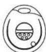
The unit is equipped with two 2-channel transmitters (art. 7208E, frequency 433.92 Mhz) and two electronic keys (CDE2).
Gemini 7090W
The system 7090W has the same functions of the 7090 but without the electronic keys and the receptacle.
USEFUL SUGGESTIONS FOR THE INSTALLATION
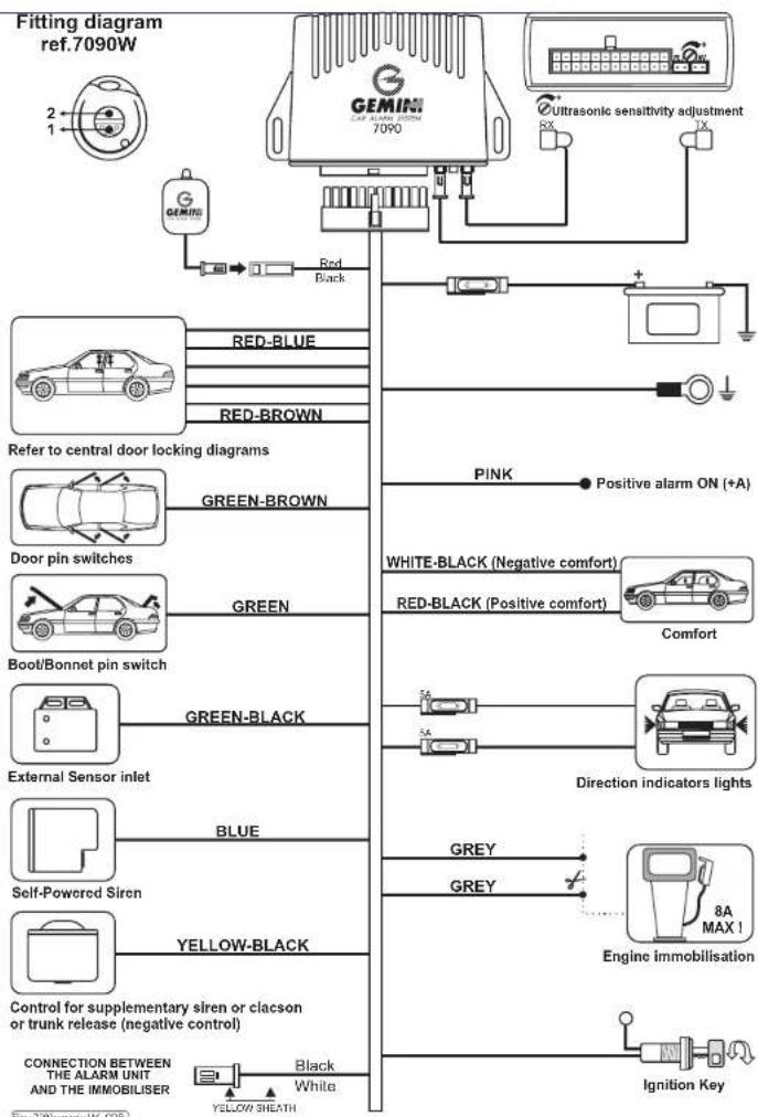
- Connect the positive and negative feeding wire of the alarm system to the battery.
- Connect always the alarm Green-Brown wire to the door pin switch.
- On catalysed vehicles the engine immobilisation must be carried out on the fuel pump and the starter motor.
- Avoid routing connection wires next to interference sources.
- The ultrasonic heads must be positioned at the top of each windscreen pillar and must be pointing at each opposite diagonal corner away from the facia outlets.
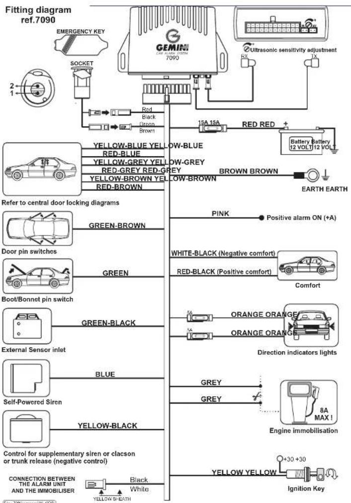
| WIRING CONNECTIONSDisconnect the negative terminal of the battery and only re-connect after the installation is complete. | ||
| FUNCTION WIRE COLOR | ||
| Earth | ↔ | BROWN |
| Battery positive terminal | ↔ | RED |
| Engine immobilisation (max. 10 A) | ↔ | 2 X GREY |
| Ignition live | ↔ | YELLOW |
| Direction Indicator lights | ↔ | 2 x ORANGE |
| Door pin switch | ↔ | GREEN-BROWN |
| Boot/bonnet pin switches | ↔ | GREEN |
| Positive alarm armed | ↔ | PINK |
| External sensors inlet | ↔ | GREEN-BLACK |
| Self-powered siren control | ↔ | BLUE |
| Additional siren negative control or klaxon | ↔ | YELLOW-BLACK |
| Comfort positive | ↔ | RED-BLACK |
| Comfort negative | ↔ | WHITE-BLACK |
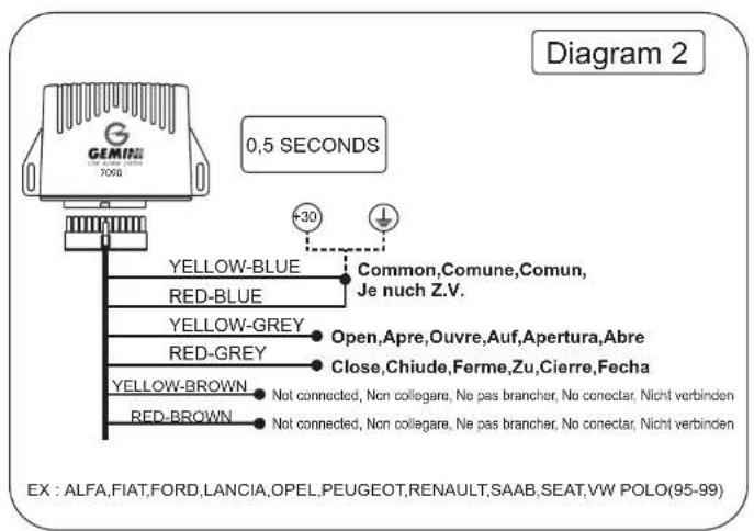
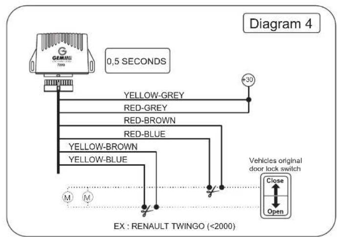
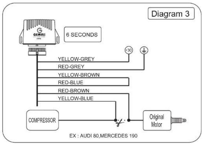
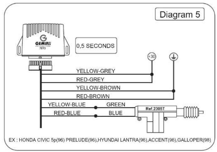
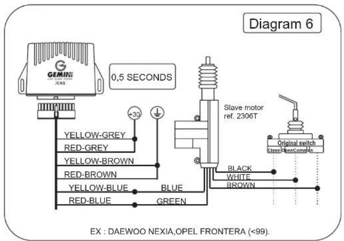
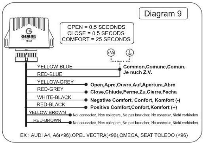
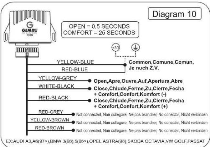
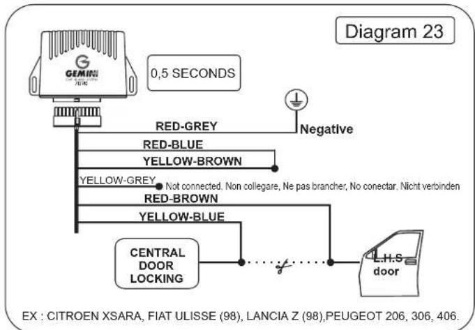
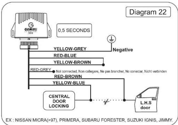
| Central door locking | ↔ | YELLOW-BLUE, RED-BLUE, YELLOW-GREY, RED-GREY, YELLOW-BROWN, RED-BROWN |
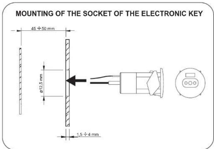
| Note: The wiring harness has 3 connectors: connect the two 2-pin connectors to the receptacle of the electronic key (art. 2390) and the connector with the thermal yellow sheath to the immobiliser. In the 7090W there are two connectors. One 2-pin connector to connect to the LED, the connector with the thermal Yellow sheath to an immobiliser. | ||
Table of programmable functions through the two-channels transmitter.
| ACTIONS | ALARM CONDITION | VISIBLE ACTIONS | LED FLASHING AND SELECTED FUNCTIONS | ALTERNATIVE ACTIONS |
| POWER OFF | Alarm OFF | - | - | - |
| Turn the ignition key to ON | Alarm OFF | - | - | - |
| FEED THE UNIT 7090 | Alarm ON | - | - | - |
| Push on the transmitter 1 button within 10 seconds | Access to the Set-up 1 function: Supplementary siren | One blinker flashing | One flashing = continuousTwo flashing = intermittent | Press the transmitter 2 button to change the selected option.De-activate +15 to memorise the selected options and to exit from User set-up. |
| Push on the transmitter 1 button | Access to the Set-up 2 function: acoustic signalling with supplementary siren | Two blinker flashing | One flashing = de-activatedTwo flashing = activated | |
| Push on the transmitter 1 button | Access to the Set-up 3 function: Panic and additional siren or boot opening through the transmitter | Three blinker flashing | One flashing = Panic and additional sirenTwo flashing = Boot opening | |
| Push on the transmitter 1 button | Access to the Set-up 4 function: boot opening while alarm armed | Four blinker flashing | One flashing = While alarm disarmedTwo flashing = For both functions | |
| Push on the transmitter 1 button | Access to the Set-up 5 function: vehicle check while arming the system | Five blinker flashing | One flashing = de-activatedTwo flashing = activated | |
| Push on the transmitter 1 button | Access to the Set-up 6 function: closure control period | Six blinker flashing | One flashing = 0,5 secondsTwo flashing = 6 seconds | |
| Push on the transmitter 1 button | Set-up function 7 function: Passive arming | Seven blinker flashing | One flashing = de-activatedTwo flashing = activated | |
| Push on the transmitter 1 button | Set-up 8 funcI voltage drop sensor | Eight blinker flashing | One flashing = de-activatedTwo flashing = activated | |
| Turn the ignition key to OFF | Set-up exit, normal working of the alarm | - | - | - |
Recapitulatory table of the programmable functions through the two-channels transmitter.
| Function | Manufacturer function | Programmable function | |
| 1 | Additional siren outlet | Continuous sound | Alternate sound |
| 2 | Acoustic signalling | De-activated | Activated |
| 3 | Boot opening with alarm disarmed | De-activated | Activated |
| 4 | Boot opening with alarm armed | De-activated | Activated |
| 5 | Vehicle's check | De-activated | Activated |
| 6 | Central door locking period | 0,5 seconds | 6 seconds |
| 7 | Passive arming | De-activated | Activated |
| 8 | Voltage drop sensor | De-activated | Activated |
WORKING DESCRIPTION
- Alarm arming with the transmitter: push on the transmitter's 1 button. One pulse of the direction indicator lights and the door closure signals the arming.
- Alarm arming with electronic key: approach the key to the appropriate socket found in the vehicle passenger's compartment. The arming is signalled through a direction indicator lights flashing; the doors closure is not activated.
- Alarm arming with exclusion of the volumetric sensor, external sensors and comfort control after the alarm arming: while alarm armed, during the inhibit time (Led lightning fix) push on the transmitter 2 button. The arming is signalled by one pulse of the direction indicator lights and the door closure, the comfort function and the sensors are excluded.
NOTE: This function de-activates at the first arming of the alarm. - Alarm disarming with the transmitter: push on the transmitter's 1 button. The disarming is signalled through 3 pulses of the direction indicator lights or 5 pulses if an alarm condition has occurred.
- Alarm disarming with the electronic key: with the alarm armed open the vehicle's door and approach the key to the appropriate socket. The disarming is signalled through 3 pulses of the direction indicator lights or 5 pulses if an alarm condition has occurred.
SPECIAL FUNCTIONS
SELF-LEARNING OF THE CODE OF A NEW TRANSMITTER OR A NEW ELECTRONIC KEY.
1. FOR THE USER.
While alarm disarmed turn the ignition key to ON, open the driver's door and push on the transmitter 2 button. The Led and the direction indicator lights activate. Turn the ignition key to OFF and push on the new transmitter 1 button or approach the electronic key to the receptacle within 8 seconds from the Led and the direction indicator lights switching off.
For each new code it is necessary to turn the ignition key to ON and then to OFF. At the end of the self-learning operation, after 8 seconds the system works normally.
2. FOR THE INSTALLER.
While alarm disarmed push on the button found in the 7090TN unit positioned in the right and rear side of the angle of the printed circuit. Turn the ignition key to ON for 1 second and then to OFF and push on the new transmitter 1 button or approach the electronic key to the receptacle.
For each self-learning of the new code it is necessary to turn the ignition key to ON for one second and then to OFF. At the end of the self-learning operation, after 8 seconds the system works normally.
NOTE: the system is supplied with a maximum number of 8 devices (transmitters and keys).
ENGINE IMMOBILISATION.
The engine immobilisation (with the 7 function activated) is obtained 60 seconds from the engine switching OFF. The Led lights quickly. To de-activate the engine immobilisation it is necessary to turn the ignition key to ON and to push on the transmitter 1 button or to approach the electronic key to the receptacle. When the Led stops flashing it is possible to start the engine.
NOTE: THE ARMING OF THE ENGINE IMMOBILISATION ACTIVATES ALWAYS 60 SECONDS AFTER THE ENGINE SWITCHING OFF (IF THE FUNCTION HAS BEEN ACTIVATED IN THE PROGRAMMING).
REMOTE CONTROLLED BOOT OPENING.
The alarm unit 7090 allows opening the vehicle boot if the control is electric and negative. This function is obtained (if the 3 function is activated) pushing on the transmitter 2 button with alarm disarmed.
If the boot opening is carried out, pushing on the transmitter 2 button with the alarm armed (if the 4 function is activated), the panic function will de-activate and all the inlets inhibit for 60 seconds. To avoid the alarm triggering, it is necessary to close the boot within this delay time. The opening of the boot is signalled by one pulse of the direction indicator lights.
PANIC FUNCTION
To obtain this function with the alarm armed after the neutral time push on the transmitter 2 button. The siren, the klaxon and the direction indicator lights activate. To de-activate this function push on the transmitter 2 button within the 10 seconds of the alarm cycle.
LEDS MEMORY.
At the alarm disarming it is possible to verify the alarm triggering cause turning the ignition key to ON. Following the Led flashing it is possible to identify the triggering cause.
| Signalling LED | Alarm triggering | Alarm cycle |
| *●* | Ultrasonic sensor | 10 |
| * * ● * * | Door and boot/bonnet pin switches. | 10 |
| * * * ● * * * | Ignition live | Unlimited |
| * * * * ● * * * * | External sensors | 10 |
| * * * * ● * * * * * | Voltage drop sensor | 10 |
| ● LED OFF (2 seconds) * LED ON (1 second) | ||
| Each alarm cycle is 30 seconds.The Inhibit time is 30 seconds for all alarm triggering's cause. | ||
GARAGE POSITION.
The user can select this function with the transmitter only if the function of the engine immobilisation has been activated. The garage position allows the user to exclude temporarily the ACTIVATION of the ENGINE IMMOBILISATION in order to leave the vehicle in the servicing or in the washing centres without giving the original transmitters or the electronic keys to the staff.
Activation of the Garage function.
- While alarm disarmed, turn the ignition key to ON.
- Turn the Ignition key to ON, within 15 sec. push on the transmitter 2 button. The LED signals the activation of the function with 2 pulses.
NOTE: do not open any door during this period. The procedure of the Garage function will automatically annul if the button is not pressed within the 15 sec. - Turn the ignition key to OFF position.
In this condition it is possible to start the engine of the vehicle for a max. of 20 attempts without obtaining the passive arming of the system.
The correct working of the GARAGE position is signalled by one acoustic signalling while starting the vehicle engine and through the fast flashing of the Led if the ignition key is in ON position.
De-activation of the Garage function.
The de-activation of the GARAGE function is obtained arming the alarm system with the transmitter or the electronic key or automatically at the end of the 20 attempts to start the engine.
ULTRASONIC ADJUSTMENT AND TEST PROCEDURE
The LED supplied with the kit is also used to signal the adjustment of the volumetric sensor.
The procedure is the following:
- Lower one of the front windows 20 cm. approximately.
- Adjust the trimmer to a medium sensitivity.
- Arm the alarm with the sensor exclusion function and wait till the end of the inhibit time signalled through the flashing Led.
- Push a hand through the open window and move it. The LED will flash when the movement has been detected. If the LED does not flash increase the sensitivity and repeat test.
TRANSMITTERS BATTERY DISCHARGING
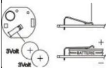
The discharging of the battery is signalled through the LED of the transmitter. If the LED does not light fix but flashes while pressing one of the transmitter's buttons it is necessary to replace the batteries.
BATTERIES: CR1616
Note: put the batteries in the appropriate container.
TECHNICAL DATA
| Power supply | 10.5-14.5 V dc. |
| Working temperature | -30^ + 85^ |
| Max. Current drawn alarm OFF | 15 mA (with self-powered siren connected) |
| Transmitters frequency | 433.92 MHz |
| Direction indicator lights relay contact capability | 10A dc |
| Engine Immobilisation relay contact capability 10A dc | |
| Outlet horn relay contact capability | 10A dc |
| Central door locking relay contact capability | 10A dc |
| Comfort positive/negative outlet capability | 100mA |
GEMINI 7147
DESCRIPTION.
GEMINI 7147 is 2 wires, high power electronic siren designed to be installed quickly and simply in the engine compartment.
CONNECTIONS.
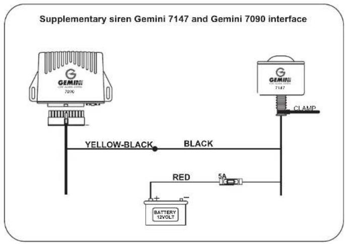
Connect the RED wire to the vehicle battery positive terminal. Connect the siren BLACK wire to the alarm YELLOW-BLACK wire.
INSTALLATION.
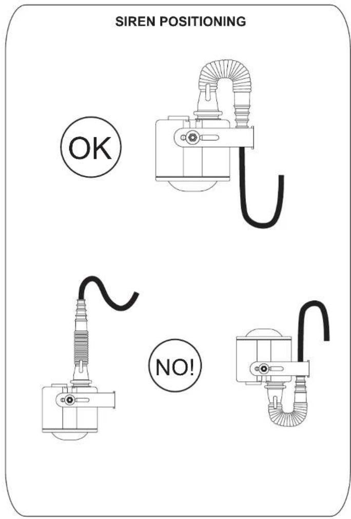
Install the siren in the engine compartment using the bracket and the screws supplied with the kit. Install the siren away from areas of intense heat and turn to low the siren ear trumpet to avoid water infiltrations. Protect the wires from water and humidity. Do not steam clean the siren.
GEMINI 7125
DESCRIPTION.
GEMINI 7125 is a high power electronic siren. It can be installed quickly and simply in the engine compartment and it can be connected to the alarm unit using the harness supplied in the kit.
WORKING DESCRIPTION.
The siren Gemini 7125 is supplied with an internal device, which allows the working of the siren also in case of absence of power supply or cutting of the connection wires of the unit. Through the codified system with alarm and siren, the alarm activate/de-activate both the battery charge and the feeding of the siren. The feeding is present only by alarm activated and 3 minutes after the alarm de-activation. Before disconnecting the siren, wait 3 minutes from the alarm do-activation.
WIRING CONNECTIONS.
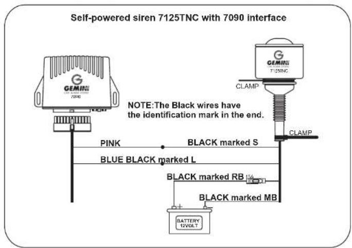
Connect the BLACK initialled RB wire to the battery positive terminal of the vehicle.
Connect the BLACK initialled MB wire to the battery negative terminal of the vehicle.
Connect the BLACK initialled L wire to the BLUE wire coming from the alarm unit.
Connect the BLACK initialled S wire to the PINK wire coming from the alarm unit.
N.B.: before supplying the siren it is necessary to CHECK the connections.
INSTALLATION.
Install the siren in the engine compartment using the bracket and the screws supplied in the kit. Install the siren away from areas of intense heat and turn to low the air trumpet of the siren in order to avoid water infiltrations. Protects the wires from water and humidity isolating connection points using protection sheath.
GEMINI 7025
DESCRIPTION.
Gemini 7025 is a self-powered, high power, electronic siren studied to install in the vehicle's engine compartment.
WORKING DESCRIPTION.
The self-powered electronic siren 7025 is supplied with an internal device, which allows the working of the siren also in case of absence of power supply or cutting of the connection wires of the unit. Through the codified system with alarm and siren, the alarm activate/de-activate both the battery charge and the feeding of the siren. The internal battery recharge activates only while alarm disarmed.
CONNECTIONS.
Connect the BLACK initialled RB wire to the vehicle battery positive terminal.
Connect the BLACK Initialled MB wire to the vehicle battery negative terminal.
Connect the BLACK initialled L wire to the alarm unit BLUE wire.
Connect the BLACK initialled S wire to the alarm unit PINK wire.
Isolate the BLACK initialled Z wire.
N.B.: before supplying the siren, check all connections.
To de-activate the alarm unit and the engine immobilisation, turn the siren key to off. The internal battery recharges while alarm de-activated.
INSTALLATION.
Install the siren in the engine compartment using the bracket and the screws supplied with the kit.
Install the siren away from areas of intense heat and turn to low the ear trumpet of the siren. Protect the siren wires from water and humidity.
This device is guaranteed against any manufacturing or working fault for 12 months from purchase date. The manufacturer declines every responsibility for any defect or failure to the device and to the electric plant of the vehicle due to an incorrect installation or to the alteration of the technical data stated in this manual.
flowchart
graph TD
    A["REF.7090W"] --> B["GEMIN 7090"]
    B --> C["Red-Black"]
    B --> D["Red-BLUE"]
    B --> E["RED-BROWN"]
    B --> F["PINK"]
    B --> G["Positive alarm ON (+A)"]
    B --> H["White-BLACK (Negative comfort)"]
    B --> I["Red-BLACK (Positive comfort)"]
    B --> J["Comfort"]
    B --> K["Green-Black"]
    B --> L["External Sensor inlet"]
    B --> M["Blue"]
    B --> N["Self-Powered Siren"]
    B --> O["YELLOW-BLACK"]
    B --> P["Control for supplementary siren or clacson or trunk release (negative control)"]
    B --> Q["CONNECTION BETWEEN THE ALARM UNIT AND THE IMMOBILISER"]
    Q --> R["Black"]
    Q --> S["While"]
    Q --> T["YELLOW SHEATH"]
    Q --> U["Ignition Key"]
flowchart
graph TD
    A["GEVIN 7000"] --> B["Yellow-GREY"]
    A --> C["RED-GREY"]
    A --> D["RED-BROWN"]
    A --> E["RED-BLUE"]
    A --> F["YELLOW-BROWN"]
    A --> G["YELLOW-BLUE"]
    B --> H["+30"]
    C --> H
    D --> H
    E --> H
    F --> I["M"]
    F --> J["M"]
    G --> K["g"]
    K --> L["EX: RENAULT TWINGO (<2000)"]
    H --> M["Closing"]
    I --> N["Open"]
    M --> O[" vehicles original door lock switch "]
    N --> O
    style A fill:#f9f,stroke:#333
    style O fill:#ccf,stroke:#333
flowchart
graph TD
    A["6 SECONDS"] --> B["Yellow-GREY"]
    A --> C["RED-GREY"]
    A --> D["YELLOW-BROWN"]
    A --> E["RED-BLUE"]
    A --> F["RED-BROWN"]
    A --> G["YELLOW-BLUE"]
    H["COMPRESSOR"] --> I["Switch"]
    I --> J["Original Motor"]
    K["EX: AUDI 80,MERCEDES 190"] --> L["+30"]
    L --> M["Ground"]
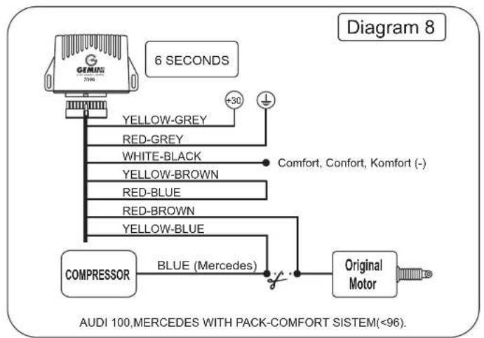
flowchart
graph TD
    A["6 SECONDS"] --> B["COMPRESSOR"]
    B --> C["BLUE (Mercedes)"]
    C --> D["Original Motor"]
    A --> E["WHITE-BLACK"]
    A --> F["YELLOW-BROWN"]
    A --> G["RED-BLUE"]
    A --> H["RED-BROWN"]
    A --> I["YELLOW-BLUE"]
    E --> J["+30"]
    F --> K["Comfort, Confort, Komfort (-)"]
    G --> L["Comfort, Confort, Komfort (-)"]
    H --> M["Comfort, Confort, Komfort (-)"]
    I --> N["Comfort, Confort, Komfort (-)"]
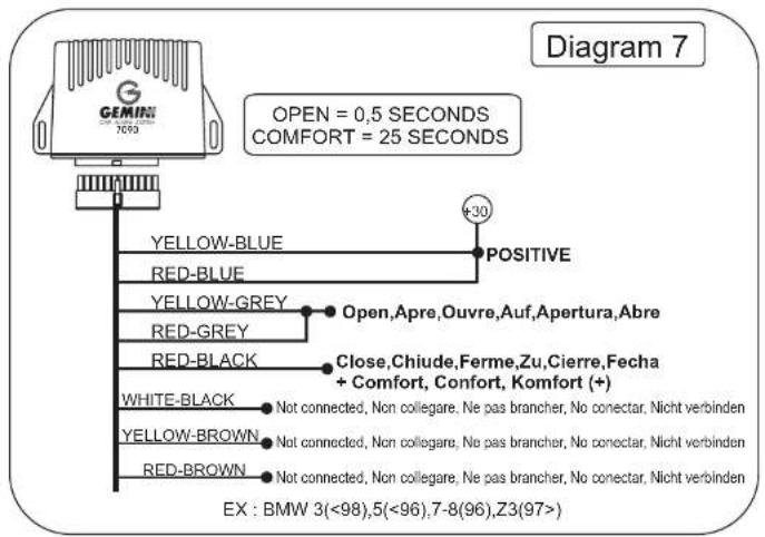
flowchart
graph TD
    A["GEMINI"] --> B["0,5 SECONDS"]
    B --> C["RED-GREY"]
    B --> D["RED-BLUE"]
    B --> E["YELLOW-BROWN"]
    B --> F["YELLOW-GREY"]
    F --> G["Not connected. Non collegare, Ne pas brancher, No conectar. Nicht verbinden"]
    F --> H["RED-BROWN"]
    F --> I["YELLOW-BLUE"]
    I --> J["..."]
    J --> K["L.H.S door"]
    L["Central DOOR LOCKING"] --> M["..."]
    M --> N["..."]
    N --> O["L.H.S door"]
flowchart
graph TD
    A["GEMIN 2050"] --> B["0,5 SECONDS"]
    B --> C["YELLOW-GREY"]
    B --> D["RED-BLUE"]
    B --> E["YELLOW-BROWN"]
    B --> F["RED-GREY"]
    F --> G["Not connected, Non collegare, Ne pas brancher, No conectar, Nicht verbinden"]
    F --> H["RED-BROWN"]
    F --> I["YELLOW-BLUE"]
    I --> J["CENTRAL DOOR LOCKING"]
    J --> K["L.H.S door"]
    K --> L["Ground"]
    style A fill:#f9f,stroke:#333
    style B fill:#ccf,stroke:#333
    style C fill:#cfc,stroke:#333
    style D fill:#cfc,stroke:#333
    style E fill:#cfc,stroke:#333
    style F fill:#fcc,stroke:#333
    style G fill:#fcc,stroke:#333
    style H fill:#fcc,stroke:#333
    style I fill:#fcc,stroke:#333
    style J fill:#cff,stroke:#333
    style K fill:#ffc,stroke:#333
    style L fill:#ffc,stroke:#333
- CERTIFICAT D'INSTALLATION
- DESCRIPTION
- GEMINI 7090
- FUNCTIONS
- Gemini 7090W
- USEFUL SUGGESTIONS FOR THE INSTALLATION
- WORKING DESCRIPTION
- SPECIAL FUNCTIONS
- SELF-LEARNING OF THE CODE OF A NEW TRANSMITTER OR A NEW ELECTRONIC KEY.
- FOR THE USER.
- FOR THE INSTALLER.
- ENGINE IMMOBILISATION.
- REMOTE CONTROLLED BOOT OPENING.
- PANIC FUNCTION
- LEDS MEMORY.
- GARAGE POSITION.
- Activation of the Garage function.
- De-activation of the Garage function.
- ULTRASONIC ADJUSTMENT AND TEST PROCEDURE
- TRANSMITTERS BATTERY DISCHARGING
- BATTERIES: CR1616
- GEMINI 7147
- DESCRIPTION.
- CONNECTIONS.
- INSTALLATION.
- GEMINI 7125
- WORKING DESCRIPTION.
- WIRING CONNECTIONS.
- GEMINI 7025
Brand : GEMINI
Model : 7090
Category : Car alarm