
7501 - Alarme auto GEMINI - Free user manual and instructions
Find the device manual for free 7501 GEMINI in PDF.


| Product Type | Self-powered car alarm system with remote control |
| Brand & Model | Gemini 7501 (also 7503 compatible) |
| Power Supply | 12 VDC (9-15 V), negative ground |
| Standby Current | < 10 mA with LED flashing |
| Remote Control Frequency | 433.92 MHz with dynamic code |
| Backup Battery | 150 mAh, 7.2 V |
| Auxiliary Output Current | Max 700 mA (PINK wire) |
| Engine Immobilizer Relay | Max 8 A (BLACK marked H) |
| Turn Indicator Relay | Max 10 A (fuse protected) |
| Siren Output | Protected by PTC resettable fuse |
| Protection Zones | Perimeter (doors, bonnet, boot), volume (ultrasound/hyperfrequency optional), power drain sensor, glass break (optional) |
| Alarm Cycle Duration | 30 seconds siren + indicators |
| Neutral Time (entry/exit) | Approx. 45 seconds (adjustable), 25 seconds for sensor cut-out |
| Memory | LED indicates last alarm cause with flash patterns |
| Remote Controlled Functions | Arm/disarm, panic alarm, car finder, sensor cut-out, siren cut-out, door lock control, comfort closure, garage mode |
| Programmable Features (8) | Sound signals, panic/car finder, power drain, anti-distraction, passive activation, lock pulse time (0.5/6 sec), comfort closure, double pulse unlock |
| Electronic Key & PIN Code | Dynamic code CDE2, 4‑digit PIN (default 1111, user programmable) |
| Learning Capacity | Up to 8 devices (remotes or electronic keys) |
| Garage Mode | Suspends anti-distraction and passive immobilizer for service |
| Warranty | 24 months from installation date |
| Operating Temperature | -30°C to +85°C (control unit), -40°C to +85°C (7059 hyperfrequency module) |
Frequently Asked Questions - 7501 GEMINI
User questions about 7501 GEMINI
0 question about this device. Answer the ones you know or ask your own.
Ask a new question about this device
Download the instructions for your Alarme auto in PDF format for free! Find your manual 7501 - GEMINI and take your electronic device back in hand. On this page are published all the documents necessary for the use of your device. 7501 by GEMINI.
USER MANUAL 7501 GEMINI
I hereby declare that the product
Is conform to all relevant essential requirements of the R&TTE-directive 1995/5/EC, issued March 9,1999. According to Annex IV of the R&TTE directive. The following standards and essential radio test suites published in the "Official Journal" of the European Communities, have been used to demonstrate the conformity of the product:
Product in class 1 frequency identification
Electrical safety
Radio and spectrum engineering parameters:
Electromagnetic Compatibility EMC:
Certificate of conformity:
Expert Opinion:
En 60950-2000
En 300220-1/1997
ETS 300683:1997
E811117M-CC
E811117M-EO
The product can be used in the following European Countries:
IR, I, L, NL, P, SP, S, UK
Company responsible for placing on the market:
GEMINI TRADING S.R.L.
Address:
Indirizzo:
Via Luigi Galvani 12 - 21020 BODIO LOMNAGO (VA) - ITALY
Point of contact:
flowchart
graph TD
    A["Wiring diagram art.7503"] --> B["7039"]
    A --> C["5123"]
    B --> D["Green/Black Brown Pink"]
    C --> D
    D --> E["AERIAL Do not tamper!"]
    E --> F["Red Black"]
    E --> G["Green Brown"]
    F --> H["15A BLACK marked R + Battery 12 V o I"]
    G --> H
    H --> I["Battery 12 V o I"]
    J["Electronic key"] --> K["ELECTRONIC Key"]
    L["See locks diagrams"] --> M["Yellow-Blue RED-BLUE"]
    L --> N["Yellow-GREY RED-GREY"]
    L --> O["Yellow-BROWN RED-BROWN"]
    P["Door pushbutton"] --> Q["BLACK marked VM"]
    R["Bonnet pushbutton"] --> S["BLACK marked V"]
    T["Boot pushbutton"] --> U["BLACK marked V"]
    V["Negative control for supplementary siren"] --> W["BLACK marked GN"]
    X["Fuses not supplied"] --> Y["ORANGE 5A"]
    X --> Z["ORANGE 5A ↑"]
    AA["Fuses not supplied"] --> AB["ORANGE 5A ↑"]
    AC["Turn indicators"] --> AD["ORANGE 5A ↑"]
    AE["Engine immobilisation"] --> AF["8A MAX"]
    AG["Ignition Key"] --> AH["+30"]
    AI["Black marked M"] --> AJ["EARTH"]
UK
INTRODUCTION
GEMINI 7503.
The 7503 system is a self-powered alarm control unit with built-in sensors and can be installed on cars having a 12-volt battery with the negative pole earthed.
DESCRIPTION
- Self-powered compact alarm control unit, remote-controlled with a dynamic code.
- Blinker and universal control to operate the centralised door locks, electric windows and roof (for cars equipped with the "pack-comfort" system).
- Boundary and volume protection.
- Controls for self-powered siren and supplementary siren (continuous sound).
- LED memory.
- Remote "panic" or car finder.
- Electrical engine immobilizer
- Electronic emergency key with dynamic code (CDE2) and emergency Pin-code.
- Control unit functions programmable by means of remote control.
-
Power supply sabotage sensor (only for version 7503).
-
like 7503 without self-powering unit
INSTALLATION TIPS
- Connect the power cable to the positive pole of the batter and the earth directly to the car frame.
- Always connect the Black alarm lead marked VM to the door pushbuttons.
- Always connect the Black alarm leads marked V to the bonnet pushbutton and the boot pushbutton.
- On cars with catalytic converters, implement the electrical engine immobilizers by pressing the fuel pump.
- If an ultrasound module is being used, position the capsules up on the RH and LH door jambs of the front windshield and aim them toward the car's interior, far from the air vents.
- Make the electrical connections and programme the accessory functions by remote control.
| ELECTRIC CONNECTIONS(REMOVE NEGATIVE POLE OF BATTERY AND RECONNECT IT ONLY AFTER ASSEMBLY IS COMPLETED) | ||
| FUNCTION WIRE COLOR | ||
| Earth | BLACK marked M | |
| Positive pole of battery | BLACK marked R | |
| Engine immobilizer 1 (max. 8A) | TWO BLACKs marked H | |
| Positive pole under key | BLACK marked G | |
| Turn indicators | TWO ORANGES | |
| Door pushbuttons | BLACK marked VM | |
| Bonnet and boot pushbutton | TWO BLACKs marked V | |
| Positive pole of alarm activated (max. 700 mA) | PINK | |
| External sensors input | GREEN-BLACK | |
| Negative control for supplementary siren | BLACK marked GN | |
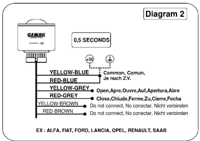
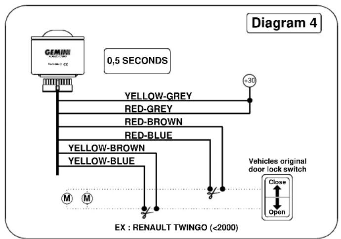
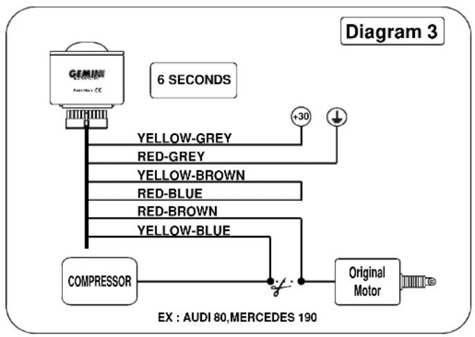
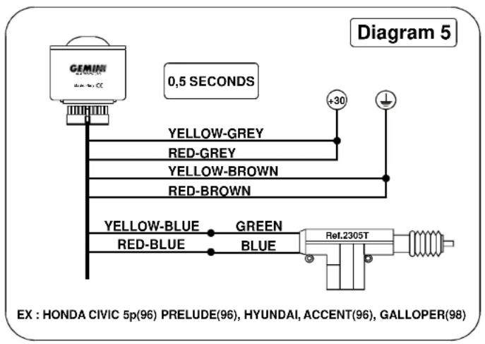
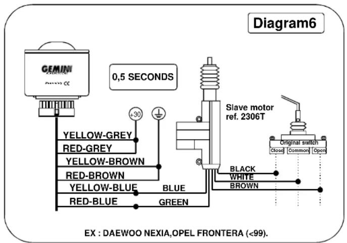
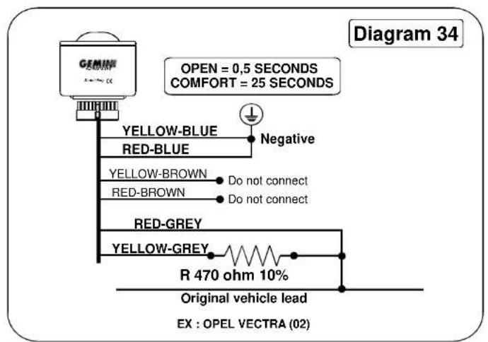
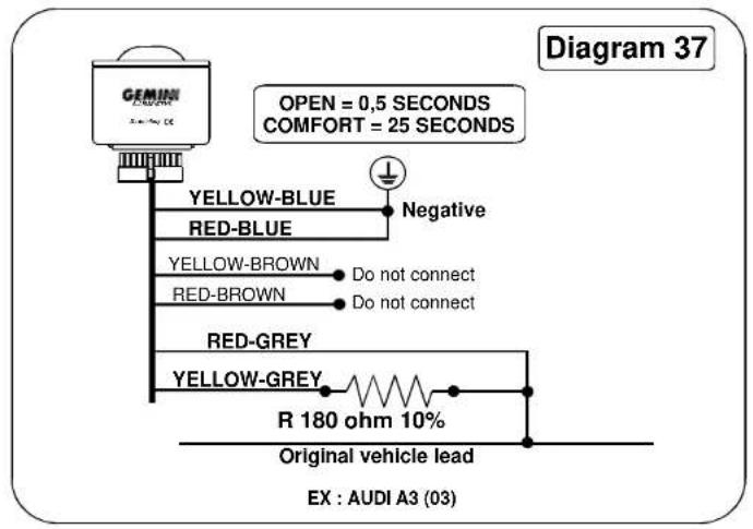
| Centralised locks | YELLOW-BLUE,RED-BLUE,YELLOW-GREY,RED-GREY,YELLOW-BROWN,RED-BROWN | |
| NOTE: In the wiring harness of the 7503 there are two 2-way connectors and one 4-way connector.The 2-way connectors must be connected to the electronic key socket (art.2390 or art.2325). If only the LED (art. 2324) is used, use only the 2-way connector with the Red wire and the Black wire.The 4-way connector serves to connect the ultrasound module or the hyperfrequency module or external modules, If fitted. | ||
ACCESSORY FUNCTIONS PROGRAMMABLE BY REMOTE.
| FUNCTION | PROGRAMMED AT FACTORY | |
| 1 | SOUND SIGNALS | ENABLED |
| 2 | PANIC ALARM / CAR FINDER | PANIC FUNCTION ENABLED |
| 3 | POWER DRAIN | DISABLED |
| 4 | ANTI-DISTRACTION - AUTOMATIC DOOR-LOCKING FUNCTION | DISABLED |
| 5 | PASSIVE ACTIVATION OF SYSTEM | DISABLED |
| 6 | SELECTION CENTRALIZED LOCK TIMES (0.5 / 6 SEC.) | 0.5 SEC. SELECTED: |
| 7 | 25-SECOND COMFORT CLOSURE COMMAND | DISABLED |
| 8 | DOUBLE PULSE WHEN OPENING | DISABLED |
ENTERING THE PROCEDURE FOR PROGRAMMING THE ACCESSORY FUNCTIONS.
Disconnect the alarm with the transmitter. Open the car door (and keep it open). Turn the ignition key to the ON position: the LED will turn on for 0.5 seconds. When the LED is on, press both keys on the remote. To confirm activation of programming mode, there will be a high beep followed by a low beep. The system is now in the programming mode and therefore it is awaiting commands that must be imparted by means of the remote control keys. During programming the LED stays on.
| VARIATION OF FUNCTION MODE.Each selection will be confirmed by a LED signal:IF YOU PRESS KEY 1 (TO ENABLE THE FUNCTION AND GO THE NEXT FUNCTION) A HIGH BEEP WILL SOUND.IF YOU PRESS KEY 2 (TO ENABLE THE FUNCTION AND GO THE NEXT FUNCTION) A LOW BEEP WILL SOUND. | |
| SOUND SIGNALS | Key 1: Enabled |
| Key 2: Disabled | |
| PANIC ALARM OR CAR FINDER | Key 1: Panic function enabledCar finder disabled |
| Key 2: Panic disabledCar finder enabled | |
| POWER DRAIN | Key 1: Enabled |
| Key 2: Disabled | |
| ANTI-DISTRACTION – AUTOMATIC DOOR-LOCKING FUNCTION | Key 1: Enabled |
| Key 2: Disabled | |
| PASSIVE ACTIVATION OF SYSTEM | Key 1: Enabled |
| Key 2: Disabled | |
| CENTRALIZED LOCK TIMES | Key 1: 6-sec time enabled |
| Key 2: 0.5 sec time enabled | |
| COMFORT COMMAND | Key 1: Enabled |
| Key 2: Disabled | |
| DOUBLE PULSE WHEN OPENING | Key 1: Enabled |
| Key 2: Disabled | |
EXITING ACCESSORY FUNCTION PROGRAMMING PROCEDURE.
You can exit the programming procedure at any time by turning the ignition key to the OFF position. At this point, the changes will be memorized and unchanged function modes will be confirmed. However, if you decide to program all the functions, the system will automatically exit the programming function. In any event, after the procedure is completed, the system will signal the end of programming the accessory functions with two low beeps and a high beep and the LED will turn off.
ACTIVATING THE ALARM SYSTEM.
The alarm can be activated by pressing key1 on the remote or by inserting the electronic key into the appropriate socket. The operation is confirmed by a visible signal consisting of one flash of the turn indicators lasting approximately one second. During the flash, the following functions are enabled:
a) Module output (PINK wire / +A)
b) LED output (lit continuously to indicate neutral activation time)
c) Engine immobilizer
d) Activation of door-locking control (with the timing selected in programming phase).
If the electronic key is used, all the functions described under points a), b) and c) will be activated, except d) ACTIVATION OF DOOR-LOCKING CONTROL which does not occur so that the user can get out of the vehicle).
Moreover, by using the electronic key, a car entry time of approximately 10 seconds will be generated to allow the user to get into the car and deactivate the alarm system with the electronic key without creating a false alarm.
While the user gets into the car, entry time is indicated by the continuous light of the LED.
NEUTRAL ACTIVATION TIME - CUTTING OUT OF EXTERNAL SENSORS / STOPPING UPWARD WINDOW / COMFORT.
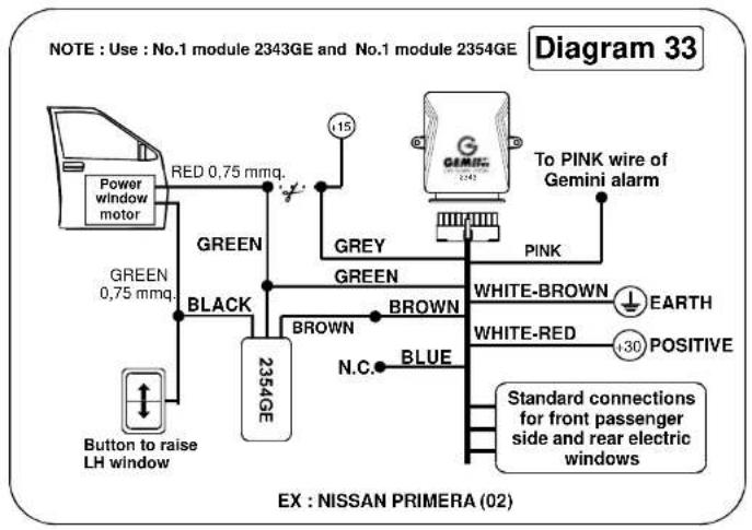
Neutral activation time lasts approx. 45" and it is indicated by the continuous light of the LED. This time interval allows the user to get out of the vehicle without causing false alarm conditions. During the first 25" of the neutral time it is possible to cut out the external sensors and stop the windows' upward travel by pressing key 2 on the remote (Note: the stop window function requires the installation of a special module – see art. 2344 – or the COMFORT function fitted on the car).
CUTTING OUT THE EXTERNAL SENSORS / STOPPING WINDOW UPWARD TRAVEL / COMFORT) IS INDICATED BY A BRIEF FLASH OF THE TURN INDICATORS.
NOTE: SENSOR CUTOUT IS LIMITED TO A SINGLE ALARM ACTIVATION CYCLE.
CUTTING OUT THE SIREN.
To cut out the sound of the siren and enable the alarm signal only through the turn indicators you must follow this procedure:
a) With the system off, turn the ignition key to the ON position – the LED will light up for about 0.5 seconds.
b) While the LED is ON (0.5 seconds), press key 2 on the remote – the LED will immediately turn off.
The siren will be cut out for the next alarm activation cycle. To reactivate the siren, just deactivate and reactivate the alarm system.
SYSTEM READY AFTER NEUTRAL TIME.
At the end of the neutral time (approx. 45"), the security system is completely armed and ready to intervene in cases of attempted theft or sabotage.
Completely armed status is indicated by the flashing of the LED, which will be piloted according to the following timing scheme in order to minimise power consumption:
LED ON : 200MS
LED OFF: 2
EVENTS THAT CAN GENERATE AN ALARM CONDITION:
a) Cutting of system wire.
b) Attempt to start engine
c) power drain. (this function is active only if enabled in the accessory function programming phase and can be used only in countries where the law does not prohibit the use of this sensor).
d) Attempt to open the doors
e) Attempt to open boot.
f) Attempt to open engine bonnet.
g) Intrusion detected by internal ultrasound volume sensor and optional external modules (even by radio).
h) Intrusion detected by external sensors (option) (also by radio).
i) Panic alarm - by pressing key 2 on the remote (this function is active only if enabled in the accessory function programming phase and it can be used only in countries where the law permits this type of alarm activation).
NOTE: In order to filter noise and/or undesired signals, the POSITIVE POLE UNDER KEY, DOORS PUSHBUTTON and BOOT PUSHBUTTON inputs have a DEBOUNCE time of 200mS. Therefore these inputs will cause the generation of an alarm cycle only if the signals coming in last longer than 200mS.
ALARM CYCLE.
An alarm cycle generated by an attempt to break in consists of the activation of the sirens connected to the alarm device (unless previously cut out) and the flashing of the turn indicators for a maximum of 30".
NOTE: During the alarm signal, the LED will be on.
You can cut off the alarm cycle without deactivating the system by pressing key 2 on the remote. As you do so, the audio/visual alarm signals will be immediately cut off, and the system will switch to the mode NEUTRAL TIME BETWEEN SUCCESSIVE ALARMS.
To minimise sound pollution in cases where the cause of the alarm persists, the DOORS PUSHBUTTON, ELECTRICAL INPUT SENSOR, and EXTERNAL SENSORS inputs are subject to a limitation of up to five alarm cycles per system activation period. The count is reset upon next deactivation of the alarm system.
NOTE: THE POSITIVE POLE UNDER KEY INPUT AND THE WIRE CUT FUNCTION HAVE NO ALARM LIMITS.
NEUTRAL TIME BETWEEN SUCCESSIVE ALARMS.
At the end of each alarm cycle there is a neutral time period, lasting up to approx. 5", during which there will be no reaction to the causes of alarm. During the neutral time between successive alarms, the LED will emit a continuous light. Normal flashing will be resumed at the end of the neutral time.
DEACTIVATING THE ALARM SYSTEM.
The alarm system can be deactivated by pressing key 1 on the remote, or by inserting the electronic key into the appropriate socket (or by means of an emergency PIN-CODE procedure during the neutral time between successive alarms).
Following this action, the centralized door-unlocking command will be implemented at once, according to the timing programmed at the installation phase, and two different types of confirmation signals will be generated:
1) DEACTIVATION WITHOUT INDICATING ALARM CONDITIONS: If no theft or break-in attempts have been detected during the surveillance period, the system will give out a visible signal consisting of three flashes of the turn indicators.
2) DEACTIVATION WITH INDICATION OF ALARM CONDITIONS: If one or more attempted thefts or break-ins have been detected during the surveillance period, the system will give out a visible signal consisting of 5 flashes of the turn indicators.
WHEN THE ALARM SYSTEM IS DEACTIVATED, THE FOLLOWING OUTPUTS / FUNCTIONS ARE DISABLED:
a) MODULE OUTPUT (PINK wire / +A)
b) LED OUTPUT
c) ENGINE IMMOBILIZER function
ACCESSORY FUNCTIONS
MEMORY OF LAST ALARM TRIGGERED:
Indications regarding the last alarm condition detected (ALARM MEMORY) are provided by the status LED as visual signals which differ as a function of the cause that has triggered the alarm. If any alarms have occurred, this signal emitted when the vehicle engine is started (positive pole under key in the ON position), after the alarm system has been turned off.
The visual signal is repeated five times and there is a 2" pause between the emission cycles. The visual signal can be cut off by turning the ignition key to the OFF position.
| LED SIGNALS REFLECTING ORIGIN OF ALARM CONDITION | CAUSE OF ALARM |
| * * * | Power drain sensor |
| * * * * * | Positive pole under key |
| * * * * * * * | Door pushbuttons |
| * * * * * * * * * | Wires cut |
| * * * * * * * * * * * | Pushbuttons for bonnet, boot and external sensors |
| * * * * * * * * * * * * | External radio sensor |
| I LED OFF (2 seconds) → LED ON (400mS) | |
Besides the accessory functions previously described (see "CUTTING OUT THE EXTERNAL SENSORS/ STOPPING WINDOW UPWARD TRAVEL / COMFORT"; "CUTTING OUT THE SIREN" and "MEMORY OF LAST ALARM TRIGGERED") the following accessory functions are available and can be programmed and used by the user or installer:
a) PANIC ALARM
b) ACTIVATION OF ANTI-DISTRACTION / AUTOMATIC DOOR-LOCKING FUNCTIONS
c) DOUBLE PULSE FOR CENTRALIZED UNLOCKING OF DOORS
d) PASSIVE ACTIVATION OF ENGINE IMMOBILIZER FUNCTION
e) GARAGE FUNCTION
PANIC ALARM / CAR FINDER
If enabled, the PANIC ALARM function allows the user to activate the visual and audio alarm signals deliberately by pressing key 2 on the remote.
This function works regardless of whether the alarm system is ON or OFF. The alarm signal lasts up to approx. 30". However, you can silence it at any time by pressing key 2 on the remote again.
Between one PANIC ALARM cycle and the next there is a neutral time of approximately 5" during which it is not possible to activate the alarm signal again.
While the alarm signal is emitted and during the consequent neutral time, the LED stays on.
IF DURING THE PROGRAMMING PHASE, THE PANIC FUNCTION HAS BEEN DISABLED, THE CAR FINDER FUNCTION WILL BE ACTIVATED.
The CAR FINDER function allows, with the ALARM ACTIVATED, you to obtain a short visual/audio signal by pressing key 2 on the remote. This function can be useful to look for the car in a parking lot or multi-storey garage without creating useless sound pollution.
The brief visual/audio signal consists of a low beep and the simultaneous flashing of the turn indicators (total length of indication is one second).
NOTE: the emission of the audio signals is subordinate to their being enabled when programming the accessory functions.
ACTIVATING THE ANTI-DISTRACTION / AUTOMATIC DOOR-LOCKING FUNCTION.
When this function is enabled, it causes the automatic activation of the alarm system if the latter has been turned off and no voluntary actions are performed by the user (e.g. OPENING A DOOR OR STARTING THE CAR) within approx. 35".
The function prevents the vehicle from being left unprotected in cases where, after the activation of
the protection system, key 1 on the remote is pressed accidentally and the alarm system is turned off by mistake.
The automatic activation of the alarm is evidenced by the regular visual signals described above.
The anti-distraction function activates the centralized door-locking control. Therefore, in order to prevent involuntary activations of the alarm system, it is INDISPENSABLE to connect the driver's side door pushbutton to the alarm system input.
In conjunction with the ACTIVATION OF THE ANTI-DISTRACTION function, the AUTOMATIC DOOR-LOCKING function is also enabled.
This function allows the automatic management of the centralized locks according to the running status of the vehicle.
The doors will lock automatically 20" after the engine is started (positive pole under key in the ON position).
The doors will unlock automatically 1" after the engine is turned off (positive pole under key in the OFF position).
Locking and unlocking times are programmed during the installation of the alarm system. To prevent this function from being activated accidentally, the system continuously monitors the status of the ignition key and the input line of the DOOR AND BOOT PUSHBUTTONS and therefore does not allow operation of the locks if the DOORS and BOOT are opened manually while starting the engine or during the 20" after starting it.
DOUBLE PULSE FOR CENTRALIZED DOOR-UNLOCKING FUNCTION
By enabling this function you will obtain, upon the deactivation of the alarm system, a double control pulse on the door-unlocking line, each pulse lasting 0.5". This allows the release of the centralized door locks on cars having the Dead-Lock function, which requires this type of signal.
The function, which can be enabled by programming during installation, is active only if the opening/closing time of 0.5" is selected.
Selecting an opening/closing time of 6" automatically excludes the double pulse upon opening.
PASSIVE ACTIVATION OF ENGINE IMMOBILIZERS
If enabled, this function automatically activates the double ENGINE IMMOBILIZER function approx. 45" after the engine is turned off. (Automatic activation of the alarm is indicated by the usual audio/visual signals already described in this document).
Activation of the PASSIVE ALARM ACTIVATION procedure is signaled, when the vehicle engine is turned off, by the flashing of the turn indicators for approximately one second, overlapped by two flashes of the LED and the simultaneous emission of two high beeps.
During the time between the activation of the PASSIVE ALARM ACTIVATION and the actual activation of the protection system, it is possible to temporarily interrupt the activation procedure by opening the DRIVER'S SIDE DOOR. This allows the user to operate calmly in the vehicle without activating the alarm system.
This pause mode is indicated by the LED emitting continuous light, and turning off when the vehicle door is closed, thus indicating the continuation of the activation count.
NOTE: audio signals will be emitted only if they have been enabled when programming the accessory functions.
GARAGE FUNCTION.
This function lets you suspend the ANTI-DISTRACTION AND PASSIVE ACTIVATION function. It can be useful for the purpose of facilitating maintenance and/or car washing operations without having to give the remotes or the electronic keys of the alarm system to the car mechanics.
To activate the GARAGE function, it is indispensable to enable the ANTI-DISTRACTION AND PASSIVE ACTIVATION functions.
Follow this procedure:
1) With the alarm system deactivated, turn the ignition key to the ON position. The status LED will turn on for approximately 0.5".
2) While the status LED is ON, press key 1 on the remote, the LED will turn off at once, reflecting the activation of the GARAGE function.
To deactivate the GARAGE function, it is sufficient to connect the alarm system with the remote.
Using the electronic key, to turn on and off the alarm system, does not reset the GARAGE function.
Learning Remote Codes
The system can learn up to 8 control devices from among the remotes and electronic keys and contacts by radio.
If the peripheral devices of the security system have been properly connected (DOOR pushbutton and BONNET pushbutton), the codes can be learned without intervening directly on the alarm control unit. This simplifies operations and reduces intervention time.
NOTE: To activate the user/installer learning procedure, the security system must be deactivated by means of a remote or an electronic key, or by entering the emergency PIN-CODE. Moreover, the PASSIVE ALARM ACTIVATION procedure must not have been activated.
If the system is in the PASSIVE ALARM ACTIVATION procedure, you must turn the system on and off with a working remote or electronic key (or wait for the passive activation to end, and then deactivate the system by entering the emergency PIN-CODE).
ACTIVATING THE LEARNING PROCEDURE:
1) Open, the driver's side door and keep it open.
2) Open the bonnet and keep it open (obviously the protection pushbutton must be connected to the alarm system).
3) Turn the ignition key to the ON position.
4) Press a previously learned remote key or put an already memorized electronic key into the appropriate socket.
The system will signal entry into the learning function procedure by emitting a visual signal consisting of two slow flashes of the turn indicators.
5) Press one of the two keys on the remote to be learned, or enter the new key to be memorized into the appropriate slot. The system will confirm the memorization of the device by emitting a visual signal consisting of one flash of the status LED.
6) Perform step 5) for all the devices to be memorised (remember: the maximum is 8).
DEACTIVATING THE LEARNING FUNCTION:
To end the learning function (after step 6), it is necessary to close the car DOOR and the BONNET and turn the ignition key to the OFF position. The system will signal the exit from the learning procedure by emitting a visual signal consisting of one flash of the turn indicators.
NOTE : THE 7503 ALARM SYSTEM DOES NOT ALLOW DELETION OF MEMORIZED DEVICES.
RELEASE PIN-CODE.
The alarm system being described here has a RELEASE PIN-CODE function which allows the user to turn off the protection device (alarm and/or engine immobilizer) if supplied remotes do not work or have been lost.
The PIN-CODE provided is made up of four digits from 1 to 9 set at the factory (1-1-1-1). The code can be personalized by the user by using a "protected" programming procedure activated by means of a working remote and the car ignition key.
RELEASING THE SYSTEM BY MEANS OF THE PIN-CODE
In order to release the system by means of the PIN-CODE, it is obviously necessary for the protection device to be in the condition of full activation, i.e. alarm providing surveillance after the initial neutral time or passive engine immobilizer activated.
In addition to knowing the exact digits of the PIN-CODE, the user must have the car ignition key.
DEACTIVATING THE ALARM:
In this situation it is necessary for the user to get into the car to cause an alarm condition. At the end of the alarm cycle (lasting approx. 30°), the system will be in the neutral time between successive alarms (duration approx. 5° – status LED emitting a continuous light). To activate the release procedure during this phase it is necessary to turn the ignition key to the ON position and then to the OFF position within approx. 3 seconds.
At the end of this operation, the status LED will turn off and the release procedure by means of the PIN-CODE can be started.
ATTENTION: if the ignition key remains in the ON position for more than three seconds during the neutral time between alarms, the system will interpret this situation as an attempted theft and therefore a new visual/audio alarm cycle will start.
Once the release procedure has begun (i.e. when the ignition key returns to the OFF position), there will be a pause of approx. 4 seconds, after which the status LED will emit an initial sequence of 9 flashes according to the following timing scheme: 0.5" ON - 1" OFF.
Each of these flashes can represent the number of the first digit of the release PIN-CODE. In other words:
1st FLASH Ü NUMBER OF 1st DIGIT
2nd FLASH Ü NUMBER OF 2nd DIGIT
3rd FLASH Ü NUMBER OF 3rd DIGIT
4th FLASH Ü NUMBER OF 4th DIGIT
5th FLASH ⬇ NUMBER OF 5th DIGIT
6th FLASH Ü NUMBER OF 6th DIGIT
7th FLASH Ⓡ NUMBER OF 7th DIGIT
8th FLASH ⬇ VALUE OF DIGIT 8
9th FLASH Ü VALUE OF DIGIT 9
To exemplify: let us suppose the PIN-CODE for the system is 4-3-2-1.
To enter the first digit (4), turn the ignition key to the ON position for at least one second during the fourth flash of the status LED, or press the pushbutton on the LED (if LED art. 2324 is used) for at least one second. This way the first digit (4) will be entered and after a pause of four seconds a new sequence of nine flashes of the status LED will occur and it will be possible to enter the second digit of the PIN-CODE (3). As in the procedure to enter the first digit, all you have to do to enter the second digit is turn the ignition key to the ON position for at least one second during the third flash of the status LED or press the pushbutton on the LED (if LED art. 2324 is used) for at least one second.
And so on for the remaining two digits (2 and 1).
After entering the fourth digit, the alarm system will be released / deactivated and the set visual signals will be emitted. Release by means of the PIN-CODE deactivates the ANTI-DISTRACTION and PASSIVE ACTIVATION OF THE ENGINE IMMOBILIZER functions. These functions will be reset upon the first system activation by remote.
In this case the system is not deactivated and the entire procedure must be repeated to attempt a new release.
If during one of the four sequences of nine flashes no digit is confirmed ("0"), at the end of the ninth flash the system will return to the normal surveillance cycle. In this case too, the entire procedure must be repeated in order to attempt a new release.
PERSONALIZING THE PIN-CODE.
As mentioned above, the PIN-CODE is set at the factory with the following digits: 1-1-1-1. These numbers are the same for all the alarms produced. Therefore the car user must personalize the release code.
This operation can be performed as follows:
a) Deactivate the alarm system by means of a remote or an electronic key.
b) Start the function programming procedure by remote (see paragraph "PROGRAMMING THE ACCESSORY FUNCTIONS").
c) When the signals indicating activation of the programming procedure are emitted, close the driver's side DOOR and keep it closed.
d) Press both keys on the remote (the status LED should stay lit).
e) Turn the car ignition key to the OFF position, and in this condition the status LED should turn off to indicate the start of memorization of the new PIN-CODE.
After a pause of approximately four seconds, the status LED will start to emit an initial sequence of nine flashes. In this case too, every flash of the LED indicates a number attributable to one digit of the PIN-CODE.
Let us suppose that the new PIN-CODE is 5-4-6-7. In order to be able to enter the number of the first digit (5), you must turn the start key to the ON position for at least one second during the fifth flash of the LED or press the pushbutton on the LED for one second (if you use LED art.2324) during the fifth flash.
After entering the number of the first digit, there will be another pause of 4 seconds, after which the status LED will emit a second sequence of nine flashes. To enter the number of the second digit (4), the ignition key must be turned to the ON position for at least one second during the fourth flash of the LED or press the pushbutton on the LED for one second (if you use LED art.2324) during the fourth flash.
To enter the remaining two digits (6 and 7), just repeat the operations described under steps f) or g), and make sure you turn the ignition key to the ON position during the sixth flash (6) or press the pushbutton on the LED for one second (if you use LED art.2324) during the seventh flash(last digit, i.e. 7).
f) When the fourth digit has been entered, the system will automatically quit the new PIN-CODE memorization procedure. This condition will be indicated by the emission of a series of visible signals similar to those indicating the end of the "PROCEDURE FOR PROGRAMMING THE ACCESSORY FUNCTIONS", a procedure you should consult for details.
WARNING: if during one of the four sequences of nine flashes of the status LED none of the numbers are confirmed (0), at the end of the ninth flash the PIN-CODE memorisation procedure will end at once.
| TECHNICAL CHARACTERISTICS | |
| Rated supply voltage | 12VDC |
| Power supply voltage range | 9Vdc to 15Vdc |
| Power drain @ 12Vdc | Less than 10 mA with system activated and flashing LED |
| Remotes | 433.92MHz – stabilized with SAW filter |
| 12V auxiliary output current | max 700 mA |
| Engine immobilizer relay contact capacity | max 8 A |
| Turn indicator relay contact capacity | max 10 A – protected by fuses |
| Back-up battery capacity | 150 mAh – with voltage of 7.2V |
| Siren output current capacity | protected with PTC integrated into circuit |
The unit is guaranteed against all manufacturing defects for 24 months after the date of installation. Please fill out the warranty certificate contained in this instruction booklet and DO NOT REMOVE the warranty label from the unit. A missing or broken label or an incomplete guarantee certificate form or the lack of a sales documents attached to it invalidates the warranty. The warranty is valid exclusively at centres authorized by Gemini Trading S.r.l. The manufacturer declines all liability for any anomalies/failures of the unit and/or the vehicle's electrical system caused by improper installation, tampering or Improper use. The alarm has the exclusive function of dissuasion from theft.
ULTRASOUND DESCRIPTION MODULE.
GEMINI 5123.
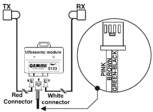
The 5123 sensor protects the car with the control of the movements obtained by saturating the passenger compartment with ultrasound waves; the opening of a door, the breaking of windows or the movement of an extraneous body inside the car are detected by the sensor which activates the alarm system by means of a command.
Installation instructions.
It is easy to connect because the wiring harness of the alarm system has a connector dedicated to connection of the sensor.
Insert sensor capsule connectors into their respective positions, one RED for connecting the TX capsule and the other WHITE for the RX capsule.
Sensitivity adjustment.
- Lower one of the front windows by about 20 cm.
- Adjust the sensitivity potentiometer to the minimum
- With the doors completely closed, connect the alarm by pressing key 2 twice.
- Introduce an foreign body into the car and shake it. The red pilot light on the module will indicate activation of the sensor after the movement is detected.
If not, increase the sensitivity and repeat the operation.
| TECHNICAL DATA AND CHARACTERISTICS | |
| Working temperature | -30^ to +85^ . |
| Working voltage 9V to 16V. | |
| Electrical input | 2.5mA. |
DESCRIPTION OF HYPERFREQUENCY MODULE.
GEMINI 7059.
The 7059 sensor protects the car by detecting intrusions into the passenger compartment through the emission of a hyperfrequency electromagnetic field (I = 2.45 Ghz).
The sensor operates according to the principle of reflection of high-frequency electromagnetic waves by means of conductors (metals, human bodies, etc.).
The measurement of these reflections makes it possible to detect extraneous objects moving within the electromagnetic field and generate an alarm signal.
The intrinsic characteristics of the 7059 sensor make it immune to air movement (e.g.: wind, turbulence, thermal variations, etc.), and therefore it is particularly suitable to be installed on convertibles, pickups or cars with sunroofs.
Since non-conductors or insulators (plastics, fabrics, etc.) are permeable to electromagnetic waves, the 7059 sensor can be installed under the upholstery of the passenger compartment thus completely hiding it from view.
INSTRUCTIONS FOR INSTALLATION
For the 7059 sensor to function properly it is of utmost importance to carefully identify the installation position, which will vary depending on the type of car.
In this regard it should be pointed out that, generally speaking, hyperfrequency sensors do not provide total protection of the passenger department, the reason being that the sensitivity must be regulated to avoid creating false alarms caused by the electromagnetic field going outside the car windows.
To prevent false alarm conditions, do not install the sensor under the glove compartment or coin tray. Moreover, the car should not have swinging metal objects inside.
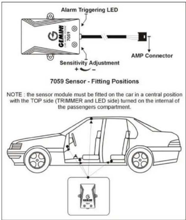
The 7059 sensor can be installed under the upholstery of the rear seat base (facing the front of the car), behind the dashboard in a central position, under the upholstery of the central tunnel or near the courtesy lights on the ceiling (under the upholstery of the car roof interior).
ELECTRICAL CONNECTIONS
The connection is very simple because the wiring harness of the alarm system has a dedicated connector for the sensor.
SENSITIVITY ADJUSTMENT
The 7059 module has a TRIMMER for adjusting sensitivity from a minimum value (not ZERO) to a maximum value. Calibration is facilitated by the presence of a red LED emitting a continuous light for 4 seconds every time there is an interference in the module's protection radius. (NOTE: between one alarm signal and the next, at least four seconds must pass after the LED turns off).
Procedure for adjusting sensitivity:
- Adjust the TRIMMER to the maximum sensitivity position (all the way clockwise).
- Connect the alarm and wait for the end of the neutral connection time, with the doors, bonnet, boots and windows closed.
- Move your hands near the car windows (lateral windows, windscreen and rear window) and make sure the 7059 sensor does not detect any alarm conditions.
- If alarm conditions occur, reduce the sensitivity of the sensor by turning the adjustment TRIMMER counterclockwise. Then repeat the test as indicated under 3).
- If the sensor does not intervene, disconnect the alarm and lower one of the front windows.
- Connect the alarm again and simulate an attempted theft by sticking your arm in through the window and moving it in proximity of the front seats to provoke the alarm intervention.
TECHNICAL DATA AND CHARACTERISTICS - 7059
| Working temperature | -40°C to +85°C. |
| Duration of alarm signal | 4 sec with a pause of 4 sec between every alarm signal. |
| Working voltage 9V to 15V. | |
| Electrical input | ≤5mA. |
| EM frequency field | 2.45 GHz ± 2.5MHz. |
7507
Introduction
The 7507 is a magnetic sensor that operates by radio waves to protect areas and goods contained in them.
This sensor can be used with Gemini alarm systems of the 7500 series or above.
Installation and Operation
The magnetic sensor and the control magnet must be fastened respectively to the fixed part and the moving part of the door or window that opens into the area to be protected (for example on the door jamb and on the door of a room or on the window jamb and the part of the window that opens).
A magnetic contact (reed switch), controlled by the position of a permanent magnet detects any forced opening of the door or window,
When the magnet is near the sensor (door or window closed), the reed switch is closed and the radio transmission is disabled.
When the magnet moves away from the sensor for a distance of about 2 cm. (door or window open), the Reed switch is opened and radio transmission is activated to the Gemini alarm system mounted on the vehicle
Testing the Operation
After mounting the 7507 sensor, check that the LED comes on for about 2 seconds when the door or window is opened. When the LED is on, the alarm signal is being transmitted and the sensor is operating correctly. If the light does not come on, make sure that the distance between the reed switch and the magnet is not greater than the distance needed to attract the reed.
NOTE: YOU SHOULD NOT POSITION THE MAGNETIC SENSOR ON METAL PARTS.
Self-learning the code
The magnetic sensor code is self-learned by the Gemini alarm system of the 7500 series or higher in the same way as the remote controls (instead of pressing the button, simply open the door or the window).
Battery Checking and Substitution
The intensity of the LED light shows the battery condition; a bright light indicates that the batteries are charged, if the LED light is dim or if it blinks, the batteries need to be replaced. To do this, follow these instructions:
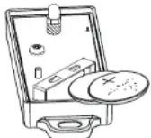
- Remove the cover;
- Take out the old batteries and insert fresh ones respecting the polarity;
- Replace and fasten the cover.
Note: Do not dispose of used batteries in the environment; always throw them away in special ecological containers.
| TECHNICAL CHARACTERISTICS | |
| POWER | 2 - 3V LITHIUM BATTERIESCR 1616 |
| STANDBY CURRENT | 1μA |
| RADIO TRANSMISSION RANGE | 20 METRES |
| TRANSMISSION FREQUENCY | 433.92 MHz |
flowchart
graph TD
    A["GEMIN CE"] --> B["0,5 SECONDS"]
    B --> C["YELLOW-GREY"]
    B --> D["RED-GREY"]
    B --> E["RED-BROWN"]
    B --> F["RED-BLUE"]
    B --> G["YELLOW-BROWN"]
    B --> H["YELLOW-BLUE"]
    G --> I["M M"]
    H --> J["g"]
    I --> K["EX : RENAULT TWINGO (<2000)"]
    J --> L[" vehicles original door lock switch "]
    L --> M["Open"]
    N["~30"] --> O["Diagram 4"]
    P["Close"] --> Q["Open"]
flowchart
graph TD
    A["GEMIN Powertrain CE"] --> B["6 SECONDS"]
    B --> C["YELLOW-GREY"]
    B --> D["RED-GREY"]
    B --> E["YELLOW-BROWN"]
    B --> F["RED-BLUE"]
    B --> G["RED-BROWN"]
    B --> H["YELLOW-BLUE"]
    C --> I["+30"]
    D --> I
    E --> I
    F --> I
    G --> I
    H --> I
    I --> J["Original Motor"]
    K["COMPRESSOR"] --> L["Switch"]
    L --> M["EX: AUDI 80,MERCEDES 190"]
flowchart
graph TD
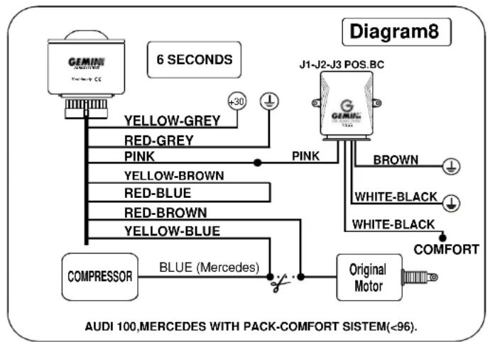
    A["GEMIN Sensor"] -->|6 SECONDS| B["Yellow-GREY"]
    A -->|6 SECONDS| C["RED-GREY"]
    A -->|6 SECONDS| D["PINK"]
    A -->|6 SECONDS| E["YELLOW-BROWN"]
    A -->|6 SECONDS| F["RED-BLUE"]
    A -->|6 SECONDS| G["RED-BROWN"]
    A -->|6 SECONDS| H["YELLOW-BLUE"]
    I["COMPRESSOR"] --> J["BLUE (Mercedes)"]
    K["J1-J2-J3 POS.BC"] --> L["BROWN"]
    K --> M["WHITE-BLACK"]
    K --> N["WHITE-BLACK"]
    K --> O["COMFORT"]
    P["Original Motor"] --> Q["Blue (Mercedes)"]
    style A fill:#f9f,stroke:#333
    style B fill:#ccf,stroke:#333
    style C fill:#ccf,stroke:#333
    style D fill:#ccf,stroke:#333
    style E fill:#ccf,stroke:#333
    style F fill:#ccf,stroke:#333
    style G fill:#ccf,stroke:#333
    style H fill:#ccf,stroke:#333
    style I fill:#fff,stroke:#333
    style J fill:#fff,stroke:#333
    style K fill:#fff,stroke:#333
    style L fill:#fff,stroke:#333
    style M fill:#fff,stroke:#333
    style N fill:#fff,stroke:#333
    style O fill:#fff,stroke:#333
    style P fill:#fff,stroke:#333
    style Q fill:#fff,stroke:#333
flowchart
graph TD
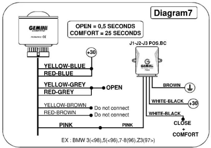
    A["GEMIN 7023 Sensor"] -->|OPEN = 0,5 SECONDS COMFORT = 25 SECONDS| B["J1-J2-J3 POS.BC"]
    A -->|YELLOW-BLUE RED-BLUE| C["+30"]
    A -->|YELLOW-GREY RED-GREY| D["OPEN"]
    A -->|YELLOW-BROWN RED-BROWN| E["Do not connect"]
    A -->|PINK| F["PINK"]
    B -->|BROWN| G["+30"]
    B -->|WHITE-BLACK| H["+30"]
    B -->|WHITE-BLACK| I["CLOSE + COMFORT"]
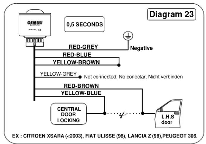
flowchart
graph TD
    A["GEMIN"] --> B["0,5 SECONDS"]
    B --> C["RED-GREY"]
    B --> D["RED-BLUE"]
    B --> E["YELLOW-BROWN"]
    B --> F["YELLOW-GREY"]
    F --> G["Not connected, No conectar, Nicht verbinden"]
    H["RED-BROWN"] --> I["YELLOW-BLUE"]
    J["CENTRAL DOOR LOCKING"] --> K["..."]
    K --> L["L.H.S door"]
    M["Diagram 23"] --> N["Negative"]
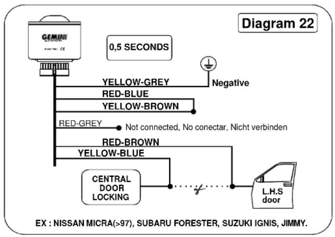
flowchart
graph TD
    A["GNIMI CHINA CE"] --> B["0,5 SECONDS"]
    B --> C["YELLOW-GREY"]
    B --> D["RED-BLUE"]
    B --> E["YELLOW-BROWN"]
    B --> F["RED-GREY"]
    F --> G["Not connected, No conectar, Nicht verbinden"]
    B --> H["RED-BROWN"]
    H --> I["YELLOW-BLUE"]
    I --> J["CENTRAL DOOR LOCKING"]
    J --> K["L.H.S door"]
    K --> L["Ground"]
flowchart
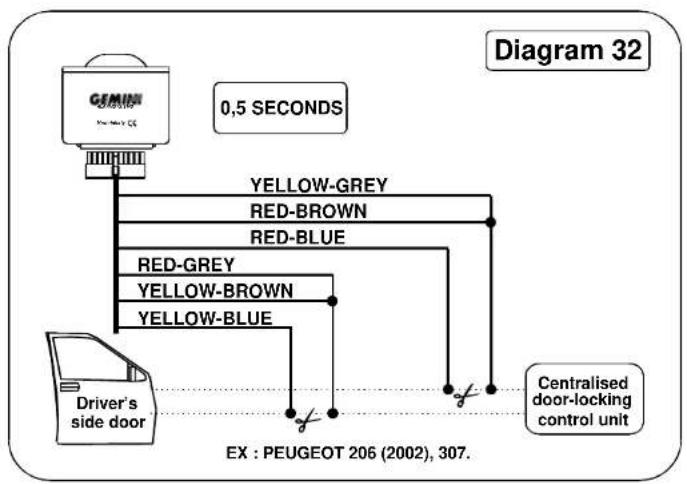
graph TD
    A["GMNN"] --> B["Driver's side door"]
    B --> C["RED-GREY YELLOW-BROWN YELLOW-BLUE"]
    C --> D["RED-BROWN RED-BLUE"]
    D --> E["0,5 SECONDS"]
    F["Centralised door-locking control unit"] --> G["EX : PEUGEOT 206 (2002), 307."]
flowchart
graph TD
    A["Power window motor"] -->|RED 0,75 mmq.| B["2354GE"]
    C["Button to raise LH window"] --> D["GREEN 0,75 mmq."]
    B --> E["BROWN"]
    E --> F["BLE"]
    F --> G["N.C."]
    G --> H["WHITE-BROWN"]
    H --> I["EARTH"]
    H --> J["WHITE-RED"]
    J --> K["POSITIVE"]
    L["To PINK wire of Gemini alarm"] --> M["PINK"]
    N["Standard connections for front passenger side and rear electric windows"] --> O["EX : NISSAN PRIMERA (02)"]
- INTRODUCTION
- GEMINI 7503.
- DESCRIPTION
- INSTALLATION TIPS
- ENTERING THE PROCEDURE FOR PROGRAMMING THE ACCESSORY FUNCTIONS.
- EXITING ACCESSORY FUNCTION PROGRAMMING PROCEDURE.
- ACTIVATING THE ALARM SYSTEM.
- CUTTING OUT THE SIREN.
- SYSTEM READY AFTER NEUTRAL TIME.
- EVENTS THAT CAN GENERATE AN ALARM CONDITION:
- ALARM CYCLE.
- NEUTRAL TIME BETWEEN SUCCESSIVE ALARMS.
- DEACTIVATING THE ALARM SYSTEM.
- WHEN THE ALARM SYSTEM IS DEACTIVATED, THE FOLLOWING OUTPUTS / FUNCTIONS ARE DISABLED:
- ACCESSORY FUNCTIONS
- MEMORY OF LAST ALARM TRIGGERED:
- PANIC ALARM / CAR FINDER
- IF DURING THE PROGRAMMING PHASE, THE PANIC FUNCTION HAS BEEN DISABLED, THE CAR FINDER FUNCTION WILL BE ACTIVATED.
- ACTIVATING THE ANTI-DISTRACTION / AUTOMATIC DOOR-LOCKING FUNCTION.
- The anti-distraction function activates the centralized door-locking control. Therefore, in order to prevent involuntary activations of the alarm system, it is INDISPENSABLE to connect the driver's side door pushbutton to the alarm system input.
- DOUBLE PULSE FOR CENTRALIZED DOOR-UNLOCKING FUNCTION
- PASSIVE ACTIVATION OF ENGINE IMMOBILIZERS
- GARAGE FUNCTION.
- Learning Remote Codes
- ACTIVATING THE LEARNING PROCEDURE:
- DEACTIVATING THE LEARNING FUNCTION:
- NOTE : THE 7503 ALARM SYSTEM DOES NOT ALLOW DELETION OF MEMORIZED DEVICES.
- RELEASE PIN-CODE.
- RELEASING THE SYSTEM BY MEANS OF THE PIN-CODE
- DEACTIVATING THE ALARM:
- PERSONALIZING THE PIN-CODE.
- ULTRASOUND DESCRIPTION MODULE.
- GEMINI 5123.
- Installation instructions.
- Sensitivity adjustment.
- DESCRIPTION OF HYPERFREQUENCY MODULE.
- GEMINI 7059.
- INSTRUCTIONS FOR INSTALLATION
- ELECTRICAL CONNECTIONS
- SENSITIVITY ADJUSTMENT
- 7507
- Installation and Operation
- Testing the Operation
- NOTE: YOU SHOULD NOT POSITION THE MAGNETIC SENSOR ON METAL PARTS.
- Self-learning the code
- Battery Checking and Substitution
Brand : GEMINI
Model : 7501
Category : Alarme auto